Language selection

Search

Patent 2630951 Summary

Third-party information liability

Some of the information on this Web page has been provided by external sources. The Government of Canada is not responsible for the accuracy, reliability or currency of the information supplied by external sources. Users wishing to rely upon this information should consult directly with the source of the information. Content provided by external sources is not subject to official languages, privacy and accessibility requirements.

Claims and Abstract availability

Any discrepancies in the text and image of the Claims and Abstract are due to differing posting times. Text of the Claims and Abstract are posted:

  • At the time the application is open to public inspection;
  • At the time of issue of the patent (grant).
(12) Patent: (11) CA 2630951
(54) English Title: AIRFOIL AND METHOD FOR PROTECTING AIRFOIL LEADING EDGE
(54) French Title: SURFACE PORTANTE ET METHODE DE PROTECTION DU BORD D'ATTAQUE DE LA SURFACE PORTANTE
Status: Deemed expired
Bibliographic Data
(51) International Patent Classification (IPC):
  • F01D 5/14 (2006.01)
  • F01D 5/28 (2006.01)
(72) Inventors :
  • SCHILLING, JAN CHRISTOPHER (United States of America)
  • SCHNEIDER, MICHAEL HARVEY (United States of America)
  • BAUR, ROBERT GEORGE (United States of America)
(73) Owners :
  • GENERAL ELECTRIC COMPANY (United States of America)
(71) Applicants :
  • GENERAL ELECTRIC COMPANY (United States of America)
(74) Agent: CRAIG WILSON AND COMPANY
(74) Associate agent:
(45) Issued: 2015-11-10
(22) Filed Date: 2008-05-08
(41) Open to Public Inspection: 2009-01-23
Examination requested: 2013-03-14
Availability of licence: N/A
(25) Language of filing: English

Patent Cooperation Treaty (PCT): No

(30) Application Priority Data:
Application No. Country/Territory Date
11/781,485 United States of America 2007-07-23

Abstracts

English Abstract

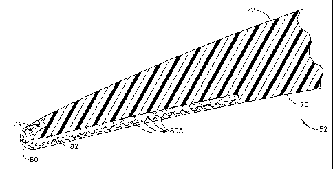
An airfoil is disclosed having a concave pressure side (70) and a convex suction side (72) defining a chord length, and a leading edge (74) and a trailing edge (76). A leading edge protective strip (80) is adhered by a bond layer (82) to and protectively covers the leading edge (74) and respective predetermined portions of the pressure side (70) and suction side (72) of the airfoil body from the leading edge (74) downstream towards the trailing edge (76). The predetermined portion of the suction side (72) covered by the leading edge protective strip (80) is less than the predetermined portion of the pressure side (70) covered by the leading edge protective strip (80).


French Abstract

Le profil aérodynamique décrit comporte un intrados concave (70) et un extrados convexe (72) définissant une longueur de corde ainsi quun bord dattaque (74) et un bord de fuite (76). Une bande de protection de bord dattaque (80) est collée par une couche de liaison (82) au bord dattaque (74) et protège celui-ci, ainsi que des parties prédéterminées respectives de lintrados (70) et de lextrados (72) du corps du profil aérodynamique, du bord dattaque (74) en aval jusquau bord de fuite (76). La partie prédéterminée de lextrados (72) recouverte par la bande de protection du bord dattaque (80) est moins importante que la partie prédéterminée de lintrados (70) recouverte par la bande de protection du bord dattaque (80).

Claims

Note: Claims are shown in the official language in which they were submitted.


WHAT IS CLAIMED IS:
1. An airfoil, comprising:
an airfoil body including a concave pressure side and a convex suction side
defining a chord length, a leading edge and a trailing edge; and
a leading edge protective strip adhered by a bond layer to and protectively
covering the leading edge and respective predetermined portions of the
pressure side
and suction side of the airfoil body from the leading edge downstream towards
the
trailing edge, wherein the predetermined portion of the suction side covered
by the
leading edge protective strip is no greater than one-third of the
predetermined portion
of the pressure side covered by the leading edge protective strip; and
wherein the leading edge protective strip comprises a multiplicity of
intersecting grooves defining adjacent segments of a predetermined size.
2. An airfoil according to claim 1, wherein the airfoil is selected from
the group consisting of a turbine engine fan blade, turbine engine compressor
blade
and a turbine engine stator vane.
3. An airfoil according to claim 1, wherein the predetermined portion
of the suction side of the airfoil covered by the leading edge protective
strip is
between about 1 and 3 percent of the chord length of the airfoil.
4. An airfoil according to claim 1, wherein the predetermined portion
of the suction side of the airfoil covered by the leading edge protective
strip is a
portion extending about 0.100 inch from the leading edge downstream towards
the
trailing edge.
5. An airfoil according to claim 1, wherein the grooves are spaced to
define segments that have sides between about 2.5 and 6.3 mm long.
6. An airfoil according to claim 1, wherein the bond layer is between
about 0.05 mm and 0.15 mm thick and the leading edge protective strip is
between
about 0.13 and 0.2 mm thick.
- 7 -


7. An airfoil according to claim 6, wherein the airfoil is selected from
the group consisting of a turbine engine fan blade, turbine engine compressor
blade,
and a turbine engine stator vane.
8. An airfoil according to claim 1, wherein the predetermined portion
of the suction side of the airfoil covered by the leading edge protective
strip is
between about 1 and 3 percent of the chord length of the airfoil, the
predetermined
portion of the suction side covered of the airfoil covered by the leading edge

protective strip is about 2.5 mm from the leading edge downstream towards the
trailing edge, the grooves are less than about 0.13 mm wide and are about one-
third
the thickness of the leading edge protective strip, the bond layer is between
about 0.05
mm and 0.15 mm thick, segments that have sides between about 2.5 mm and 6.3 mm

long and the leading edge protective strip is between about 0.13 mm and 0.2 mm

thick, and wherein the inwardly-facing grooves provide increased surface area
for
attachment of the leading edge protective strip to the airfoil.
9. A method of protecting the leading edge of an airfoil, comprising
the steps of:
providing an airfoil body including a concave pressure side and a convex
suction side defining a chord length, and a leading edge and a trailing edge;
forming in a leading edge protective strip a multiplicity of intersecting
grooves defining adjacent segments of a predetermined size; and
adhering the leading edge protective strip to and protectively covering the
leading edge and respective predetermined portions of the pressure side and
suction
side of the airfoil body from the leading edge downstream towards the trailing
edge,
wherein the predetermined portion of the suction side covered by the leading
edge
protective strip is no greater than one-third of the predetermined portion of
the
pressure side covered by the leading edge protective strip.
10. A method according to claim 9, wherein the predetermined portion
of the suction side covered of the airfoil covered by the leading edge
protective strip is
between about 1 and 3 percent of the chord length of the airfoil.
- 8 -


11. A method according to claim 9, wherein the grooves are less than
about 0.13 mm wide and are about one-third the thickness of the leading edge
protective strip.
12. A method according to claim 9, wherein the bond layer is between
about 0.05 mm and 0.15 mm thick and the leading edge protective strip is
between
about 0.13 and 0.2 mm thick.
13. A method according to claim 9, wherein the airfoil is selected from
the group consisting of a turbine engine fan blade, a turbine engine
compressor blade
and a turbine engine stator vane.
14. A turbine engine, comprising a low pressure compressor, a high
pressure compressor, a high pressure turbine, a low pressure turbine and a
combustor,
and a plurality of radially-extending stator vanes, at least one of the stator
vanes
comprising:
a vane body including a concave pressure side and a convex suction side
defining a chord length, and a leading edge and a trailing edge; and
a leading edge protective strip adhered by a bond layer to and protectively
covering the leading edge and respective predetermined portions of the
pressure side
and suction side of the vane body from the leading edge downstream towards the

trailing edge, wherein the area of the predetermined portion of the suction
side
covered by the leading edge protective strip is no greater than one-third of
the area of
the predetermined portion of the pressure side covered by the leading edge
protective
strip; and
wherein the leading edge protective strip comprises a multiplicity of
inwardly-facing, intersecting grooves defining adjacent segments of a
predetermined
size.
15. A turbine engine according to claim 14, wherein the predetermined
portion of the suction side of the vane covered by the leading edge protective
strip is
between about 1 and 3 percent of the chord length of the vane.
- 9 -


16. A turbine engine according to claim 14, wherein the predetermined
portion of the suction side of the vane covered by the leading edge protective
strip is
about 2.5 mm from the leading edge downstream towards the trailing edge.
17. A turbine engine according to claim 14, wherein the grooves are less
than about 0.13 mm wide and are about one-third the thickness of the leading
edge
protective strip.
- 10 -

Description

Note: Descriptions are shown in the official language in which they were submitted.


CA 02630951 2008-05-08
218217-1

AIRFOIL AND METHOD FOR PROTECTING AIRFOIL LEADING EDGE
BACKGROUND OF INVENTION

The subject matter disclosed in this application relates generally to
compressor
airfoils and a method for protecting airfoil leading edges, and more
specifically to
composite material fan blades and stator vanes having a metallic leading edge
strip.

Many modern turbine engine fan blades and stator vanes are constructed of a
composite laminate or molded fiber. These include the Joint Strike Fighter
(JSF) F136
engine and the well-known CF6-80C2 high bypass engine. Erosion of the vane
material
within the harsh environment of the engine is prevented by a V-shaped
protective metallic
strip which is wrapped around the leading edge and covers a substantial
percentage of
both the suction and pressure sides of the vanes. In prior art constructions,
fitting the
metallic leading edge strip is difficult, principally because of the
difficulty in controlling
the thickness uniformity of the adhesive layer that bonds the metallic strip
to the vane.
The leading edge of modern airfoils is relatively sharp, and the fitup of the
metallic strip
to the leading edge is not exact.

Experience with composite stator vanes has shown that the thin metal strips
bonded to the leading edge of the airfoil for erosion protection may become
detached
during engine operation. Detachment is typically due to bonding failure caused
by strain
mismatch between the metal strip and the composite material of the blade or
vane during
operation at elevated temperatures. Detachment of leading edge strips can
cause
unacceptable domestic object damage (DOD) to airfoils and other engine
components
located downstream in the engine flow path.

An important element in controlling bonding integrity is the ability of the
bond
material to act as a compliant layer between the composite material and the
metal strip
to absorb the strain mismatch. When detachment occurs, the structure of the
current
leading edge strips does not permit control of the size of the detached strip
fragments,
-1-


CA 02630951 2008-05-08
218217-1

leading to the possibility of downstream ingestion of relatively large,
irregularly-shaped
metallic material and consequent engine damage.

Therefore, there exists a need to prevent detachment of protective leading
edge
strips from airfoil leading edges and to minimize damage to downstream engine
components in the event of detachment.

BRIEF DESCRIPTION OF THE INVENTION

According to one aspect of the invention, an airfoil is provided that includes
an
airfoil body including a concave pressure side and a convex suction side
defining a chord
length, and a leading edge and a trailing edge. A leading edge protective
strip is adhered
by a bond layer to, and protectively covers, the leading edge and respective
predetermined
portions of the pressure side and suction side of the airfoil body from the
leading edge
downstream towards the trailing edge. The predetermined portion of the suction
side
covered by the leading edge protective strip is substantially less than the
predetermined
portion of the pressure side covered by the leading edge protective strip.

According to another aspect of the invention, a method of protecting the
leading
edge of an airfoil includes the steps of providing an airfoil body including a
concave
pressure side and a convex suction side defining a chord length, and a leading
edge and
a trailing edge, and adhering a leading edge protective strip to and
protectively covering
the leading edge and respective predetermined portions of the pressure side
and suction
side of the airfoil body from the leading edge downstream towards the trailing
edge,
wherein the predetermined portion of the suction side covered by the leading
edge
protective strip is no greater than one-third of the predetermined portion of
the pressure
side covered by the leading edge protective strip.

BRIEF DESCRIPTION OF DRAWINGS

Some aspects of the invention have been set forth above. Other aspects of the
invention will appear as the invention proceeds when taken in conjunction with
the
following drawings, in which:

-2-


CA 02630951 2008-05-08
218217-1

FIG. 1 is a simplified perspective view of a gas turbine engine;

FIG. 2 is a partial schematic side elevation view of an exemplary gas turbine
engine high pressure compressor assembly;

FIG. 3 is a perspective view of a single stator vane;

FIG. 4 is a partial cross-section of the vane in FIG. 3, taken along lines
4B4; and
FIG. 5 is a side elevation view of a single stator vane according to an
alternative
embodiment of the invention.

DETAILED DESCRIPTION AND BEST MODE OF THE INVENTION

Referring now to FIG. 1, a gas turbine engine 10 is shown schematically, and
includes a low pressure compressor 12, a high pressure compressor 14, and a
combustor
16. Engine 10 also includes a high pressure turbine 18 and a low pressure
turbine 20.
Compressor 12 and turbine 20 are coupled by a first shaft 24, and compressor
14 and
turbine 18 are coupled by a second shaft 26.

In operation, air flows through low pressure compressor 12, is compressed and
supplied from the low pressure compressor 12 to high pressure compressor 14.
The
highly compressed air is delivered downstream to combustor 16 where the air is
mixed
with fuel and ignited. The ignited air/gas mixture from the combustor 16
drives the
turbines 18 and 20.

As is shown in FIG. 2, the high pressure compressor assembly 14 includes a
plurality of stages, and each stage includes an array of radially-extending
rotor blades 40
and an array of radially-extending stator vane assemblies 44. In the exemplary
embodiment, rotor blades 40 are supported by rotor disks 46 and are coupled to
rotor
shaft 26. Rotor shaft 26 is surrounded by a casing 50 that extends
circumferentially
around compressor 14 and supports the stator vane assemblies 44.

In the exemplary embodiment shown in FIG. 2, at least the inlet guide vane
assembly 44 includes a stator vane 52 that includes a radially outer vane stem
or spindle
-3-


CA 02630951 2008-05-08
218217-1

54 that extends substantially perpendicularly from a vane platform 56. Each
spindle 54
extends through a respective opening 58 defined in casing 50 to enable a
respective vane
52 to be coupled to casing 50. Casing 50 includes a plurality of openings 58.
A lever arm
60 extends from each variable vane 52 and is utilized to selectively rotate
vanes 52 for
changing the orientation of vanes 52 relative to the flowpath to facilitate
increased control
of airflow through compressor 14. It is understood that the invention
disclosed in this
application may be used on vanes and blades without regard to whether the
vanes or
blades have variable pitch. While at present airfoil temperatures in the
compressor 14 are
typically too hot for vanes made of known composite materials except for the
inlet guide
stator vane 52, shown with a leading edge strip 80 according to an embodiment
of the
invention. Metallic leading edge protective strips on any one or more vanes,
as described
below, are considered within the scope of the invention, since further
advances may
render practical composite material vanes throughout the compressor.

As is best shown in FIGS. 3 and 4, the stator vane 52 includes an airfoil body
formed of a polymeric composite of known type, and having a concave pressure
side 70
and a convex suction side 72, FIG. 4, defining a chord length, a leading edge
74 and a
trailing edge 76.

A leading edge protective strip 80 is adhered by a bond layer 82 to, and
protectively covers, the leading edge 74 and respective predetermined portions
of the
pressure side 70 and suction side 72 of the airfoil body from the leading edge
74
downstream towards the trailing edge 76. Erosion of the leading edge 74 is
typically
more severe on the pressure side 70 of the vane 52 and, accordingly, as shown
with
particular reference to Figure 4, the predetermined portion of the suction
side 72 covered
by the leading edge protective strip 80 is therefore much less than the
portion of the
pressure side 70 covered by the leading edge protective strip 80. This
facilitates a more
accurate control of the thickness of the bond layer 82 which in turn leads to
superior bond
strength.

The vane 52 can be "bowed" out of plane with respect to a radial line
extending
through the engine axis. This is done to accommodate the aerodynamic effects
at the
-4-


CA 02630951 2008-05-08
218217-1

airfoil inner and outer flowpath. However, this bow can further complicate the
fit
between the leading edge protective strip 80 and the vane 52, and makes the
design
described herein, with the leading edge protective strip 80 principally on the
pressure side
70, particularly desirable.

The leading edge protective strip 80 is preferably metallic, and is selected
to
have thermal expansion and comformability characteristics suitable for the
polymeric
composite from which the vane 52 is formed. Titanium is one suitable metal for
this
purpose. The leading edge protective strip 80 is preferably about less than
0.25 mm
thick, with a thickness in the range of about 0.13 mm to 0.2 mm thick. As is
shown
schematically in Figure 4, the length of the leading edge protective strip 80
extending
around the leading edge 74 and onto the suction side 72 is about 2.5 mm, or
more
generally about 2-3 percent of the airfoil chord length. Empirically, the
degree of
extension of the leading edge protective strip 80 onto the suction side 72
must be
sufficient to prevent the edge of the leading edge protective strip 80 from
being separated
from the vane 52 and lifted by airflow/gas pressure.

The thickness and material of the bond or "compliant" layer 82 is determined
by analysis in order to reduce shear stresses between the leading edge
protective strip 80
and the vane 52. The material of the bond layer 82 is preferably bismaleimide
(BMI) or
a fluoroelastomer such as manufactured and sold by DuPont under the trademark
Viton , in order to provide stable, long-lasting performance in the 204-260 C.
engine
environment. Bond thickness is preferably on the order of 0.05 mm to 0.15 mm.

As is representationally shown in Figures 3 and 4, the leading edge protective
strip 80 is grooved with interior-facing grooves 80A to define small
geometrically-shaped
segments of a size sufficiently small that, if detached from the airfoil
during engine
operation, impact with downstream engine components would not cause damage to
the
downstream engine components. The grooves 80A preferably form segments that
have
sides between about 2.5 mm and 6.3 mm long. The grooves 80A themselves are on
the
order of about 0.13 mm wide with a depth that is about one-third the thickness
of the
leading edge protective strip 80. The grooves 80A may define squares,
diamonds, other
-5-


CA 02630951 2008-05-08
218217-1

quadrilateral shapes, or any other suitable shape. The outer surface of the
leading edge
strip 80 is smooth and is intended to provide an essentially turbulance-free
transition from
the adjacent vane surface. The inner, grooved surface additionally provides a
greater
surface area on the inner face of the leading edge strip 80 to thereby provide
an enhanced
bond between the leading edge strip 80 and the underlying bond layer 82.

As is shown in Figure 5, the leading edge protective strip 80 may optionally
be
provided with axially-extending adjustment slits 84 radially spaced along the
vane 52, by
which the leading edge protective strip 80 can be more precisely fitted to the
shape of the
leading edge 74 of the vane 52. The slits 84 have shallow, inwardly-tapered
draft angles
that are closed together when applied so that the opposing edges of the slits
84 touch.

An airfoil with a metallic leading edge strip and a method for protecting the
leading edge of an airfoil is described above. This written description uses
examples to
disclose the invention, including the best mode for practicing the invention,
and also to
enable any person skilled in the art to practice the invention, including
making and using
any devices or systems and performing any incorporated methods. The patentable
scope
of the invention is defined by the claims, and may include other examples that
occur to
those skilled in the art. Such other examples are intended to be within the
scope of the
claims if they have structural elements that do not differ from the literal
language of the
claims, or if they include equivalent structural elements with insubstantial
differences
from the literal language of the claims.

-6-

Representative Drawing
A single figure which represents the drawing illustrating the invention.
Administrative Status

For a clearer understanding of the status of the application/patent presented on this page, the site Disclaimer , as well as the definitions for Patent , Administrative Status , Maintenance Fee  and Payment History  should be consulted.

Administrative Status

Title Date
Forecasted Issue Date 2015-11-10
(22) Filed 2008-05-08
(41) Open to Public Inspection 2009-01-23
Examination Requested 2013-03-14
(45) Issued 2015-11-10
Deemed Expired 2019-05-08

Abandonment History

There is no abandonment history.

Payment History

Fee Type Anniversary Year Due Date Amount Paid Paid Date
Application Fee $400.00 2008-05-08
Maintenance Fee - Application - New Act 2 2010-05-10 $100.00 2010-04-20
Maintenance Fee - Application - New Act 3 2011-05-09 $100.00 2011-04-19
Maintenance Fee - Application - New Act 4 2012-05-08 $100.00 2012-04-19
Request for Examination $800.00 2013-03-14
Maintenance Fee - Application - New Act 5 2013-05-08 $200.00 2013-04-18
Maintenance Fee - Application - New Act 6 2014-05-08 $200.00 2014-04-22
Registration of a document - section 124 $100.00 2015-02-20
Maintenance Fee - Application - New Act 7 2015-05-08 $200.00 2015-04-23
Final Fee $300.00 2015-07-17
Maintenance Fee - Patent - New Act 8 2016-05-09 $200.00 2016-05-02
Maintenance Fee - Patent - New Act 9 2017-05-08 $200.00 2017-05-01
Owners on Record

Note: Records showing the ownership history in alphabetical order.

Current Owners on Record
GENERAL ELECTRIC COMPANY
Past Owners on Record
BAUR, ROBERT GEORGE
SCHILLING, JAN CHRISTOPHER
SCHNEIDER, MICHAEL HARVEY
Past Owners that do not appear in the "Owners on Record" listing will appear in other documentation within the application.
Documents

To view selected files, please enter reCAPTCHA code :


To view images, click a link in the Document Description column. To download the documents, select one or more checkboxes in the first column and then click the "Download Selected in PDF format (Zip Archive)" or the "Download Selected as Single PDF" button.

List of published and non-published patent-specific documents on the CPD .

If you have any difficulty accessing content, you can call the Client Service Centre at 1-866-997-1936 or send them an e-mail at CIPO Client Service Centre.


Document
Description 
Date
(yyyy-mm-dd) 
Number of pages   Size of Image (KB) 
Abstract 2008-05-08 1 19
Description 2008-05-08 6 283
Claims 2008-05-08 3 99
Representative Drawing 2009-01-09 1 14
Cover Page 2009-01-22 1 46
Drawings 2008-05-08 5 85
Claims 2014-09-30 4 131
Representative Drawing 2015-10-16 1 14
Cover Page 2015-10-16 1 45
Assignment 2008-05-08 3 107
Prosecution-Amendment 2013-03-14 1 39
Correspondence 2014-05-02 1 24
Prosecution-Amendment 2014-04-07 3 128
Prosecution-Amendment 2014-09-30 9 304
Assignment 2015-02-20 9 300
Final Fee 2015-07-17 1 34