Language selection

Search

Patent 2631473 Summary

Third-party information liability

Some of the information on this Web page has been provided by external sources. The Government of Canada is not responsible for the accuracy, reliability or currency of the information supplied by external sources. Users wishing to rely upon this information should consult directly with the source of the information. Content provided by external sources is not subject to official languages, privacy and accessibility requirements.

Claims and Abstract availability

Any discrepancies in the text and image of the Claims and Abstract are due to differing posting times. Text of the Claims and Abstract are posted:

  • At the time the application is open to public inspection;
  • At the time of issue of the patent (grant).
(12) Patent: (11) CA 2631473
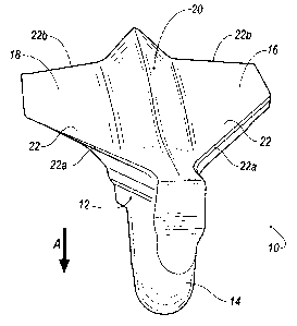
(54) English Title: AGRICULTURAL FURROWING TOOL
(54) French Title: OUTIL DE LABOURAGE AGRICOLE
Status: Granted and Issued
Bibliographic Data
(51) International Patent Classification (IPC):
  • A01C 5/06 (2006.01)
(72) Inventors :
  • BERGEN, HENRY J. (Canada)
(73) Owners :
  • GEN MANUFACTURING LTD.
(71) Applicants :
  • GEN MANUFACTURING LTD. (Canada)
(74) Agent: SMART & BIGGAR LP
(74) Associate agent:
(45) Issued: 2009-09-08
(22) Filed Date: 2008-04-04
(41) Open to Public Inspection: 2009-04-17
Examination requested: 2008-04-04
Availability of licence: N/A
Dedicated to the Public: N/A
(25) Language of filing: English

Patent Cooperation Treaty (PCT): No

(30) Application Priority Data:
Application No. Country/Territory Date
11/874,181 (United States of America) 2007-10-17

Abstracts

English Abstract

A ground engaging furrowing tool for paired row seeding comprising a body having a forward leading point, a bottom and laterally outwardly extending wing members. Each wing member including a leading edge that flares rearward to a trailing edge to form a generally V-shaped profile bottom surface, the trailing edge of each wing member including a seed outlet only open in a rearward direction.


French Abstract

Outil de labourage de semis en lignes jumelées comprenant un corps doté d'une pointe avant, d'un fond et d'ailes s'étendant vers l'extérieur. Chaque aile comprend un bord d'attaque qui s'évase vers l'arrière jusqu'au bord de fuite et forme une surface inférieure essentiellement en forme de v. Le bord de fuite de chaque aile comprend un canal d'évacuation ouvert uniquement vers l'arrière.

Claims

Note: Claims are shown in the official language in which they were submitted.

What is claimed is:
1. An agricultural furrowing tool, comprising:
a body of unitary construction having a forward leading point, a bottom, a top
and laterally outwardly extending wing members, each wing member including a
leading
edge that flares rearward to a trailing edge such that the bottom has a
generally continuous V-
shaped profile, the body further including a single seed inlet formed in the
top of the body
proximate the forward leading point and a pair of seed outlets formed in the
top of the body,
one of the seed outlets formed within one wing member proximate the trailing
edge and the
other one of the seed outlets formed within the other wing member proximate
the trailing
edge, the see inlet located between the seed outlets such that the material
dispensed from the
seed inlet travels downwardly and rearwardly to the seed outlets.
2. An agricultural furrowing tool, comprising:
a body of unitary construction having a forward leading point with respect to
a
direction of travel of the body, a bottom, a top and laterally outwardly
extending wing
members, each wing member including a leading edge that flares rearward to a
trailing edge
such that the bottom has a generally continuous V-shaped profile, the body
further including
a seed inlet formed in the top of the body proximate the forward leading point
and a seed
outlet formed in the top of the body within each wing member proximate the
trailing edge
such that the material dispensed from the seed inlet travels downwardly and
rearwardly to the
seed outlet such that the material exits the body in an opposite direction
with respect to the
direct of travel of the body.
-5-

Description

Note: Descriptions are shown in the official language in which they were submitted.


CA 02631473 2009-03-04
AGRICULTURAL FURROWING TOOL
FIELD OF THE INVENTION
[0001] This invention relates generally to implements for planting
agricultural crops in the
ground and, more particularly, to a point of an agricultural furrowing tool
for closed bottom
paired row seeding.
BACKGROUND OF THE INVENTION
[0002] Planting crops using a power drawn seed boot may entail different
requirements
depending upon the type of crop being planted, whether the farmer is
undertaking single or
multiple row planting, soil quality, and other variables. Seed boots must vary
in their
discharge capabilities accordingly. It would be possible to maintain one seed
boot for each
variety of planting. However, this increases the burden of a farmer's capital
expenditures, and
also complicates preparation for each successive planting where different
seeding patterns
must be practiced. The complication is that for each planting, a different
seed boot may be
required.
[0003] An example of a seed boot is shown in U.S. Patent No. 6,745,705.
[0004] Ideally, seeds are spaced evenly over an entire field. However, for
practical
purposes, seeds are planted in rows by ground working tools. The rows are
spaced to achieve
the best possible utilization of the soil area. Other factors affect row
spacing, such as the need
to allow field trash from prior years growth to pass between ground working
tools while also
arranging the ground working tools in a pattern which produces a smooth field
surface. This
has led to development of ground working tools which plant two rows of seed or
a wide band
of seed to achieve good seedbed utilization with fewer number of ground
working tools and
greater space between these tools thus allowing good trash flow. It is also
common that these
tools are designed to simultaneously place a row of fertilizer beside and
below the seeds, or
between the rows of seeds, thereby eliminating a need for fertilizing in a
second pass and
placing the fertilizer more accurately than is achievable in a separate pass.
[0005] One type of planting tool is known to have a standard sweep in a
leading position
for forming a furrow having a level or flat seedbed on which a pair of seed
rows are placed,
one to each side of the seedbed. The furrow is closed by soil passing over
wings extending to
the sides of the sweep. The tool further includes a second furrowing element
comprising a
rearwards angled blade for forming a second, deeper furrow between the rows of
seed from 1
-1-

CA 02631473 2009-03-04
inch to 2.5 inches deep. A fertilizer dispensing tube is secured to the blade
and also angles
rearwards with the blade to dispense fertilizer into the second furrow.
[0006] It will be appreciated that further improvements in the known prior art
designs are
desired.
SUMMARY OF THE INVENTION
[0007] It is an object of this invention to overcome the aforementioned
disadvantages of the
prior art by providing an improved point of an agricultural furrowing tool for
closed bottom
paired row seeding
[0008] These and other objects, features and advantages are accomplished
according to the
instant invention by providing a ground engaging furrowing tool for paired row
seeding
comprising a body having a forward leading point, a bottom and laterally
outwardly
extending wing members. Each wing member including a leading edge that flares
rearward
to a trailing edge to form a generally V-shaped profile bottom surface, the
trailing edge of
each wing member including a seed outlet only open in a rearward direction.
BRIEF DESCRIPTION OF DRAWINGS
[0009] The advantages of this invention will be apparent upon consideration of
the
following detailed disclosure of the invention, especially when taken in
conjunction with the
accompanying drawings wherein:
[0010] FIG. 1 is a bottom perspective forward view of a furrowing tool for
paired row
seeding incorporating the principles of the instant invention; and
[0011 ] FIG. 2 is a top perspective rearward view of the furrowing tool shown
in FIG. 1.
-2-

CA 02631473 2009-03-04
DETAILED DESCRIPTION OF PREFERRED EMBODIMENTS
[0012] Fig. 1 of the drawings shows a ground engaging furrowing tool 10 of a
seed boot
(not shown). In a preferred embodiment, the ground engaging tool 10 is a
bottom point
paired row seeder configuration for discharging fluent materials such as seed
and other
substances into the ground.
[0013] The ground engaging furrowing tool 10 comprises a body 12 having a
forward
leading point 14, a right side 16 and a left side 18. Right side 16 and left
side 18 are
respectively the right and left surfaces of the body 12 with respect to the
forward direction
indicated as arrow A. The body 12 includes a mounting portion that extends
upwardly and is
adapted for securing the body to the seed boot. The forward leading point 14
is the forward
most part of seed boot when being drawn by a tractor or the like (not shown)
in actual use.
[0014] The body 12 includes a bottom 20, a top 21 and laterally outwardly
extending wing
members 22. Each wing member 22 includes a leading edge 22a that flares
rearward to a
trailing edge 22b such that the bottom has a generally continuous V-shaped
profile. A seed
inlet 23 is formed in the top 21 of the body 12 proximate the forward leading
point 14, and a
seed outlet 24 is formed within each wing member 22 proximate the trailing
edge 22b. A
seed dispensing passage extends from the seed inlet 23 to the pair of spaced
apart seed outlets
24 within each wing member 22 such that material dispensed from the seed inlet
23 travels
downwardly and rearwardly to the seed outlet 24.
[0015] In an operating orientation, material such as a seed stream entering
the seed inlet
moves downward and rearward to the paired seed outlets 24 to exit from the
trailing edge 22b
of each wing member 22 with a rearward velocity and direction. The seed
outlets 24 are
formed in the trailing edge 22b of each wing member 22 and only open in
rearward direction.
Conventional ground entering points of seed boots include seed outlets that
open downward.
It will be appreciated that a rearward opening seed outlet 24 in accordance
with the present
invention will not plug with soil, trash and the like during use.
[0016] The seedbed furrowing tool is securable to the main tool body by a
fastener as well
known in the art.
[0017] The component typically operates with the leading edge 22a from 0.5
inches to 4
inches below the surface of the ground. Ground is cut by the leading edge 22a
and V-shaped
bottom to form a seedbed and the cut soil flows up over the wings 22.
-3-

CA 02631473 2008-04-04
The ground surface is penetrated by the upper narrow portion of the component
which
slices through the ground with minimal disturbance. Ground that had been
displaced
by the seedbed furrowing tool begins to flow back over the seedbed after the
rear end
passes by.
[0019] It will be appreciated that the furrowing tool 10 may be made of an
assembly
of modular components including a furrowing tool and a fertilizer furrowing
component as well known in the art. In addition, material delivery passages
have
been described above for seed, but it is understood that other combinations of
materials can be planted into the ground with a tool of this design such as
fertilizer,
dispensing pesticide or herbicide in place of the fertilizer stream or
alternating seed
and fertilizer streams, although the best known mode of operation is with
planting
paired seed rows.
[0020] While the invention has been specifically described in connection with
certain specific embodiments thereof, it is to be understood that this is by
way of
illustration and not of limitation, and the scope of the appended claims
should be
construed as broadly as the prior art will permit.
-4-

Representative Drawing
A single figure which represents the drawing illustrating the invention.
Administrative Status

2024-08-01:As part of the Next Generation Patents (NGP) transition, the Canadian Patents Database (CPD) now contains a more detailed Event History, which replicates the Event Log of our new back-office solution.

Please note that "Inactive:" events refers to events no longer in use in our new back-office solution.

For a clearer understanding of the status of the application/patent presented on this page, the site Disclaimer , as well as the definitions for Patent , Event History , Maintenance Fee  and Payment History  should be consulted.

Event History

Description Date
Letter Sent 2024-04-04
Common Representative Appointed 2019-10-30
Grant by Issuance 2009-09-08
Inactive: Cover page published 2009-09-07
Inactive: Final fee received 2009-06-15
Pre-grant 2009-06-15
Notice of Allowance is Issued 2009-05-21
Letter Sent 2009-05-21
Notice of Allowance is Issued 2009-05-21
Inactive: Approved for allowance (AFA) 2009-05-13
Application Published (Open to Public Inspection) 2009-04-17
Inactive: Cover page published 2009-04-16
Advanced Examination Determined Compliant - PPH 2009-03-04
Advanced Examination Requested - PPH 2009-03-04
Inactive: First IPC assigned 2008-12-18
Inactive: IPC assigned 2008-12-18
Inactive: Office letter 2008-06-25
Inactive: Filing certificate - RFE (English) 2008-06-19
Filing Requirements Determined Compliant 2008-06-19
Letter Sent 2008-06-19
Application Received - Regular National 2008-06-19
Request for Examination Requirements Determined Compliant 2008-04-04
All Requirements for Examination Determined Compliant 2008-04-04

Abandonment History

There is no abandonment history.

Owners on Record

Note: Records showing the ownership history in alphabetical order.

Current Owners on Record
GEN MANUFACTURING LTD.
Past Owners on Record
HENRY J. BERGEN
Past Owners that do not appear in the "Owners on Record" listing will appear in other documentation within the application.
Documents

To view selected files, please enter reCAPTCHA code :


To view images, click a link in the Document Description column. To download the documents, select one or more checkboxes in the first column and then click the "Download Selected in PDF format (Zip Archive)" or the "Download Selected as Single PDF" button.

List of published and non-published patent-specific documents on the CPD .

If you have any difficulty accessing content, you can call the Client Service Centre at 1-866-997-1936 or send them an e-mail at CIPO Client Service Centre.


Document
Description 
Date
(yyyy-mm-dd) 
Number of pages   Size of Image (KB) 
Description 2008-04-04 4 187
Abstract 2008-04-04 1 12
Claims 2008-04-04 1 16
Drawings 2008-04-04 2 21
Description 2009-03-04 4 182
Drawings 2009-03-04 2 20
Representative drawing 2009-03-20 1 7
Cover Page 2009-04-14 2 34
Claims 2009-03-04 1 39
Cover Page 2009-08-18 1 32
Commissioner's Notice - Maintenance Fee for a Patent Not Paid 2024-05-16 1 556
Acknowledgement of Request for Examination 2008-06-19 1 177
Courtesy - Certificate of registration (related document(s)) 2008-06-19 1 103
Filing Certificate (English) 2008-06-19 1 157
Commissioner's Notice - Application Found Allowable 2009-05-21 1 162
Reminder of maintenance fee due 2009-12-07 1 111
Correspondence 2008-06-19 1 13
Correspondence 2009-06-15 1 40
Fees 2014-01-28 1 23
Fees 2015-01-12 1 24
Fees 2016-02-02 1 24
Fees 2017-01-25 1 24
Maintenance fee payment 2018-01-19 1 24
Maintenance fee payment 2019-01-21 1 24
Maintenance fee payment 2020-03-04 1 25
Maintenance fee payment 2022-06-06 1 25