Note: Descriptions are shown in the official language in which they were submitted.
CA 02631588 2008-05-29
WO 2007/064683 PCT/US2006/045649
ELECTRICAL CONDUIT TO JUNCTION BOX CONNECTION SYSTEM
REFERENCE TO RELATED DOCUMENTS
This application claims the benefit of a previous application filed in the
United States
Patent and Trademark Office by Robert K. Sheehan, on November 30, 2005, titled
"Electrical
Conduit To Junction Box Connection System," and given serial number
11/291,627, now
U.S. Patent No. 7,078,623 issued on July 18, 2006.
TECHNICAL FIELD
The instant invention relates to adapters for connecting electrical conduit to
junction
boxes, outlet boxes, or other enclosures, and, more particularly, to an
electrical conduit
connector with a compression nut and a body, that together provide a system
for connecting a
conduit to a junction box in a quick, safe, and rigid fashion.
BACKGROUND OF THE INVENTION
The most common use for electrical conduit connectors is to facilitate the
connection
of a conduit or cable to a junction box. The junction box can be a variety of
electrical
enclosures such as an outlet box, transformer enclosure, circuit panel,
lighting fixture - the
list is nearly endless. Similarly, the conduit can be rigid or flexible, or
could be hose, other
tubing capable of routing electrical wire, or cable. Cable can be non-metallic
sheathed cable,
Io portable cord, or a variety of other types of electrical conductors. The
instant invention is
equally successful in connecting a plurality of types of conduits, cables, and
other electrical
conductors to a wide variety of boxes and other enclosures. Therefore, as used
in this
specification, the term conduit is not limited to standard rigid electrical
conduit, but shall be
1
CA 02631588 2008-05-29
WO 2007/064683 PCT/US2006/045649
intended to mean any type of conduit, any type of cable, or any other type of
electrical
conductor. Many commercial and residential buildings have electrical
installations with many
types of conduit-to-junction-box connections that utilize electrical
connectors.
The two most common types of electrical connectors used are a snap-in
connector,
and a multipart connector which may be composed of two or more components that
utilizes a
threaded male end in conjunction with a threaded female locknut, hereinafter
referred to
collectively as a two-part locknut connector, without intent to limit such
connectors to two
parts only. In the case of the two-part locknut connector, the male threaded
end is inserted
into the junction box through a knockout. A rigid connection is established by
threading the
lock nut onto the male end in the junction box interior. The snap-in connector
is another
commonly used connector which utilizes a snap ring to quickly connect it to
the junction box.
Either type of connector, is integrated with an adapter end which allows the
attachment of
conduit, cable, or a variety of types of hollow tubing.
The installation of electrical systems is generally expensive as an
electrician must first
install the enclosures, route conduit between each enclosure, and install
connectors and then
pull all necessary electrical wiring through the conduit. In other words,
installation is
expensive because it is labor intensive. The commercially available electrical
connectors are
one factor accentuating the labor intensiveness. Two-part locknut connectors
increase the cost
of installing electrical systems for a number of reasons.
The current art two-part locknut connectors are plagued with labor intensive
problems. First, the two-part locknut connectors are shipped from the
manufacturer
preassembled. That is, the electrician must first remove the locknut from the
male end before
it can be installed. Once the male end of the connector is placed through the
knockout, the
electrician must rethread the locknut onto the connector from the interior of
the junction box.
2
CA 02631588 2008-05-29
WO 2007/064683 PCT/US2006/045649
Two hands are required to disassemble and then reassemble the connectors in
the knockout.
Consequently, it is difficult to hold a tool or a piece of conduit while
reassembling the
connector. Once the locknut is threaded it must be tightened. In accordance
with many
building codes and safety regulations, connectors must be firmly and reliably
attached to
junction boxes. To properly tighten the two-part locknut connector, the
electrician must use a
tool, usually a set of pliers or a screwdriver. Occasionally, when the proper
tool is
unavailable, an electrician will use any object within reach. These
situations, while rare, raise
serious safety issues. In many instances, however, to "get the job done" the
locknut is
"finger" tightened. Those persons skilled in the art know that finger
tightened two-part
locknut connectors can eventually loosen, and a loose connector can cause
great strain to be
put onto the electrical wires and their connections resulting in an increase
in the probability
of an electrical fire or other electrical problems, such as poor grounding.
Secondly, when the electrician disassembles the fitting by taking the locknut
off the
connector, the locknut can be dropped or misplaced. This can occur when the
electrician is in
an elevated position, such as, on a scissor lift or on scaffolding because
electrical conduit is
often installed in out-of-the-way places like in rafters and above ceilings.
If the locknut
cannot be found, the connector is useless. If the electrician decides to
retrieve the dropped
locknut, the installation time is prolonged.
A third common problem with the present two-part locknut connectors is the
locknut
is easily cross threaded onto the male thread. When this occurs, the
electrician must usually
use a tool to remove the locknut. On occasion, cross threading the locknut
will damage the
male threads on the connector making it difficult or impossible to reuse the
connector. Again,
the electrician must spend their time either removing the defective connector
or forcing the
locknut through the damaged portion of the threads.
3
CA 02631588 2008-05-29
WO 2007/064683 PCT/US2006/045649
A fourth problem with the present two-part locknut connectors is the distance
the
male end protrudes into the junction box. In some installations, the space
inside the enclosure
is already minimal. The space limitation becomes an acute problem when an
additional
connector is installed. The male threaded end protrudes well past the depth of
the locknut and
may interfere with another connector, the contents of the enclosure, or wiring
inside the box.
Therefore, in a limited space enclosure, the excess thread must be removed.
Typically, the
electrician saws off the excess thread, or may clip off some of the receptacle
or mounting
screws, or completes a combination of space enlarging modifications, all of
which prolong
installation time and threaten the integrity of the system as designed.
A fifth common problem with the present two-part locknut connectors occurs
during
disassembly of the connector from the enclosure. Electricians may disassemble
an installation
for a variety of reasons. The disassembly of the two-part locknut connector is
more time
consuming than the installation. If the locknut was installed properly, that
is, by tightening it
with a tool, then the locknut must be removed with a tool. Similar to the
installation, if the
threads are damaged during disassembly, the connector is useless. Also similar
to the
installation problems, if the locknut is lost, it must be replaced if the
connector is to be used
again. If the connector was "modified" during installation because space
inside the enclosure
was limited, disassembly may be exceedingly difficult or impossible due to the
probability
that the threads on the male connector have been damaged.
The snap-in connector presents similar problerns. However, the most
significant
problem is that these connectors, in most cases, do not create a rigid
connection. Because the
snap ring is sized to accept a variety of box wall thickness, it does not
rigidly attach to many
boxes. The loose fit may cause electrical continuity problems, a highly
dangerous situation,
4
CA 02631588 2008-05-29
WO 2007/064683 PCT/US2006/045649
since the box, the conduit, and the connector are intended to be part of the
electrical
grounding system in some applications.
Another problem with the snap ring devices is that they are inherently not
liquid tight.
As is commonly known in the industry, liquid tight refers to the connector's
propensity to
prohibit liquids from penetrating through the connector and into the junction
box. Many
applications require the connections of the conduit to the electrical
enclosures to be
impervious to any liquids found in the surrounding environment, whether the
liquid is water,
hydraulic fluid,, or any other fluid found in industry. In these applications,
liquid tight
connectors are required for safety purposes, specifically to avoid
electrocuting those nearby
and to avoid fire. Since, as stated previously, the snap-in connectors do not
create a rigid
connection, they cannot be confidently utilized in liquid tight applications.
There remains an unfulfilled need to provide a generally universal connector
which
can be installed quickly and easily without tools, does not require access to
the interior of the
junction box, and does not need to be disassembled before connecting it to an
electrical
enclosure. Additionally, there remains an unfulfilled need to provide a
generally universal
connector providing a rigid; and where required by code, an electrically
conductive
connection; conserves space within the enclosure; and can be made to be liquid
tight.
SUMMARY OF INVENTION
In its most general configuration, the present invention advances the state of
the art
with a variety of new capabilities and overcomes many of the shortcomings of
prior devices
in new and novel ways. In its most general sense, the present invention
overcomes the
shortcomings and limitations of the prior art in any of a number of generally
effective
5
CA 02631588 2008-05-29
WO 2007/064683 PCT/US2006/045649
configurations. The instant invention demonstrates such capabilities and
overcomes many of
the shortcomings of prior methods in new and novel ways.
The electrical conduit to junction box connection system of the instant
invention is
designed to be installed quickly and easily without tools, does not require
access to the
interior of the junction box, and does not need to be disassembled before
connecting it to a
junction box. Additionally, the instant invention improves safety because it
provides a rigid
connection, it conserves space within the enclosure, and it can be made to be
liquid tight.
The instant invention connects a conduit to a junction box. Typically, the
junction box
has a number of prefabricated holes each of which is called a knockout. To
insert any
connector to the junction box, the knockouts must be exposed by knocking out a
cover piece.
Alternatively, some junction boxes do not have removable covers for exposing
prefabricated
knockouts. In this situation the knockout is cut in the desired location with
a punch and die
set or a drill bit.
The electrical conduit to junction box connection system of the instant
invention
includes a body and a compression nut. The body has a body interior surface.
The body
interior surface defines an inlet diameter and an outlet diameter. The outlet
diameter is
coaxial with the inlet diameter. In an embodiment of the instant invention, a
conduit stop
projects from the body interior surface a conduit stop projection distance.
The distance that
the conduit can be inserted into the body is limited by the conduit stop and
is called a conduit
insertion distance. Furthermore, the body is composed of three regions.
The first region is a box engagement region. The box engagement region is
positioned
at one end of the body and cooperates with the knockout to attach the body to
the junction
box. The box engagement region has a leading and a follower tab which extend
radially from
the box engagement region. Also, within the box engagement region is a root
surface. The
6
CA 02631588 2008-05-29
WO 2007/064683 PCT/US2006/045649
root surface facilitates the connection of the system to the junction box. The
root surface has
a root surface diameter that is not coaxial with the body inlet or the body
outlet diameter. The
leading tab has a perimeter edge, a centering ledge, and a centering flank.
The leading tab
centering flank extends from the root surface to the leading tab centering
ledge. A flank angle
exists between the leading tab centering flank and the leading tab centering
ledge. The flank
angle is between approximately ninety-one degrees and approximately one
hundred and
seventy-nine degrees. The follower tab also has a perimeter edge and a primary
contact
surface. The leading tab perimeter edge and the follower tab perimeter edge
form a tab
perimeter diameter. The perimeter diameter is larger than the knockout
diameter.
The second region is a nut engagement region which has a plurality of threads
that
cooperate with the compression nut. The third region is a conduit engagement
region. The
conduit engagement region has a conduit compression system for frictionally
gripping or
clamping the conduit thereby securing the conduit within the body.
The compression nut is another primary component of the system. The
compression
nut operates to rigidly fix the body to the junction box by compressing the
junction box wall
between the leading and follower tabs and the compression nut. The compression
nut has an
exterior surface which can be designed to accept tools or be shaped to allow
operation by
hand. In either case, operation of the compression nut is accomplished on the
outside of the
junction box - the electrician is not required to,thrust tools or their hand
inside the junction
box. The compression nut will forcibly engage the exterior surface of the
junction box, with
or without tools, thereby providing the desired rigid, space saving, and
liquid tight
connection.
The design of the electrical conduit to junction box connection system
facilitates the
connection of the conduit to the junction box for r unning electrical wiring
and the like to
7
CA 02631588 2008-05-29
WO 2007/064683 PCT/US2006/045649
proceed quickly and easily. Consequently, users will realize substantial labor
cost savings
versus assembly with prior art systems. Initially, the leading tab is inserted
from the outside
of the box through the knockout by angling the body such that the central axis
is not
orthogonal to the knockout. Once the leading tab is on the inside of the
junction box, the
knockout edge is brought into contact with the root surface. The central axis
is oriented
orthogonally to the knockout while holding the knockout edge in contact with
the root
surface. In this manner the follower tab clears the knockout edge and passes
through the
knockout into the junction box. At this point both the leading and follower
tabs are on the
inside of the junction box. The body is drawn tight to the junction box by
rotating the
compression nut so that the nut contact edge presses against the box exterior
surface. In one
embodiment, the compression nut and nut engagement region threads are left-
handed threads,
that is, reverse from the normal orientation, to enhance effectiveness of the
system. By
continuing to rotate the compression nut, the nut contact edge forces the
knockout edge onto
the leading tab centering flank. Further rotation of the compression nut
pushes the knockout
edge onto the leading tab centering ledge, substantially centering the body
into the knockout
and compressing the junction box between the compression nut and the leading
and follower
tabs. The system is disconnected from the junction box by reversing the above
operation.
Once the body is secured to the junction box through the knockout, the conduit
is
attached to the system by inserting the conduit leading edge into the conduit
engagement
region. In one embodiment of the instant invention, the conduit leading edge
is inserted into
the conduit engagement region to the conduit stop. In another embodiment, the
conduit
compression system frictionally secures the conduit to the body. In those
embodiments in
which there is no conduit stop, as in, by way of example and not limitation,
those
embodiments designed to hold flexible cable, where the cable is simply
inserted through the
8
CA 02631588 2008-05-29
WO 2007/064683 PCT/US2006/045649
body into the connector to an adequate depth to assure a firm grip by the
connector on the
cable. The electrical wires or cables may pass through the conduit, through
the body interior
surface, and into the junction box.
The system of the instant invention enables a significant advance in the state
of the
art. The instant invention is, in addition, widely applicable to a large
number of applications.
The various embodiments, as would be understood by one skilled in the art,
would be suitable
to any application requiring the joining of conduit to electrical junction
boxes of various
types. These variations, modifications, alternatives, and alterations of the
various preferred
embodiments may be used alone or in combination with one another, as will
become more
readily apparent to those with skill in the art with reference to the
following detailed
description of the preferred embodiments and the accompanying figures and
drawings.
BRIEF DESCRIPTION OF THE DRAWINGS
Without limiting the scope of the present invention as claimed below and
referring
now to the drawings and figures:
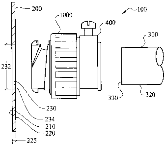
-FIG. 1 is an elevation view of an embodiment of the electrical conduit to
junction box
connection system, not to scale;
FIG. 2 is an elevation view of components of an embodiment of the electrical
conduit
to junction box connection system, not to scale, showing a compression nut
separated from a
body for clarity;
FIG. 3 is a cross-sectional view of components of an embodiment of the
electrical
conduit to junction box connection system, not to scale, with exploded views
of both a
leading tab and a follower tab;
9
CA 02631588 2008-05-29
WO 2007/064683 PCT/US2006/045649
FIG. 4 is a cross-sectional view of components of an embodiment of the
electrical
conduit to junction box connection system, not to scale, with exploded views
of both a
leading tab and a follower tab;
FIG. 5 is a cross-sectional view of components of an embodiment of the
electrical
conduit to junction box connection system, not to scale;
FIG. 6 is a cross-sectional view of components of an embodiment of the
electrical
conduit to junction box connection system, not to scale, illustrating a
conduit compression
system;
FIG. 7 is an elevation view of components of an embodiment of the electrical
conduit
to junction box connection system, not to scale, illustrating a first step in
the insertion of a
body into a junction box;
FIG. 8 is an elevation view of components of an embodiment of the electrical
conduit
to junction box connection system, not to scale, illustrating'a further step
in the insertion of a
body into a junction box;
FIG. 9 is an elevation view of components of an embodiment of the electrical
conduit
to junction box connection system, not to scale, illustrating yet a further
step in the insertion
of a body into a junction box;
FIG. 10 is an elevation view of components of an embodiment of the electrical
conduit to junction box connection system, not to scale, illustrating even yet
a further step in
the insertion of a body into a junction box;
FIG. 11 is an elevation view of components of an embodiment of the electrical
conduit to junction box connection system, not to scale, illustrating a final
step in the
insertion of a body into a junction box;
CA 02631588 2008-05-29
WO 2007/064683 PCT/US2006/045649
FIG. 12 is an elevation view of components of an embodiment of the electrical
conduit to junction box connection system, not to scale;
FIG. 13 is a cross-sectional view of components of an embodiment of the
electrical
conduit to junction box connection system with a removable conduit engagement
region, not
to scale;
FIG. 14 is an elevation view of components of an embodiment of the electrical
conduit to junction box connection system with a removable conduit engagement
region, not
to scale;
FIG. 15 is an elevation view of components of an embodiment of the electrical
1'o conduit to junction box connection system, not to scale;
FIG. 16 is a cross-sectional view of components of an embodiment of the
electrical
conduit to junction box connection system, not to scale;
FIG. 17 is an elevation view of components of an embodiment of the electrical
conduit to junction box connection system with left-handed threads, not to
scale; and
FIG. 18 is a cross-sectional view of components of an embodiment of the
electrical
conduit to junction box connection system, not to scale.
~~
CA 02631588 2008-05-29
WO 2007/064683 PCT/US2006/045649
DETAILED DESCRIPTION OF THE INVENTION
The electrical conduit to junction box connection system (100) of the instant
invention
enables a significant advance in the state of the art. The preferred
embodiments of the device
accomplish this by new and novel arrangements of elements and methods that are
configured
in unique and novel ways and which demonstrate previously unavailable but
preferred and
desirable capabilities. The detailed description set forth below in connection
with the
drawings is intended merely as a description of the presently preferred
embodiments of the
invention, and is not intended to represent the only form in which the present
invention may
be constructed or utilized. The description sets forth the designs, functions,
means, and
methods of implementing the invention in connection with the illustrated
embodiments. It is
to be understood, however, that the same or equivalent functions and features
may be
accomplished by different embodiments that are also intended to be encompassed
within the
spirit and scope of the invention.
An electrical conduit to junction box connection system (100) is designed to
quickly,
safely, and rigidly connect to a junction box (200) to facilitate the
connection of a conduit
(300) to the junction box (200). The instant invention is equally successful
in connecting a
plurality of types of conduits (300), cables, and other electrical conductors
to a wide variety
of boxes (200). Therefore, as used in this specification, the term conduit is
not limited to
standard rigid electrical conduit, but shall be intended to mean any type of
conduit, any type
of cable; or any other type of electrical conductor. The junction box (200) is
one of many
types of electrical enclosures, such as, outlet and fixture boxes, enclosures
for disconnect
switches and motor starters, and transformer enclosures. The junction box
(200) may be made
from steel, plastic, or other commercially feasible and acceptable materials.
Referring to FIG.
1, the junction box (200) has a box interior surface (210), a box exterior
surface (220), and a
12
CA 02631588 2008-05-29
WO 2007/064683 PCT/US2006/045649
box thickness (225). Typically, the junction box (200) has a plurality of
prefabricated holes
each of which is covered with a plate or is formed with a thin area in the
junction box (200)
commonly called a knockout (230). To insert a connector to the junction box
(200), the
knockout (230) must be exposed by knocking out the cover piece or perforating
the thin area.
Alternatively, some junction boxes (200) do not have removable covers or thin
areas that can
be prepped to receive a connector. In this situation, knockouts (230) are cut
in the desired
location'with a punch and die set. In either the prefabricated or on-site-
cutting box design, the
knockout (230) has a knockout diameter (232) and a knockout edge (234). The
conduit (300)
may be rigid or flexible conduit, or any type of hollow tubing commonly used
in electrical
installations. The conduit (300) may be made from steel, plastic, or other
commercially
feasible and acceptable material. The conduit (300) has a conduit interior
surface (310), a
conduit exterior surface (320), a conduit thickness (340), and a conduit
leading edge (330), as
seen generally in FIGS. 1 and 2. The two primary components will be briefly
described so the
operation of the system (100) may be explained.
The electrical conduit to junction box connection system (100) includes a body
(400)
and a compression nut (1000). As seen generally in FIGS. 1 - 3, the body (400)
has a distal
end (410), a proximal end (420), a body interior surface (430), and a body
exterior surface
(450). The body interior surface (430) defines an inlet diameter (432) and an
outlet diameter
(434). The outlet diameter (434) is coaxial with the inlet diameter (432). A
central axis (436)
intersects the outlet and inlet diameters (434,432) midpoints. In one
embodiment of the
instant invention, a conduit stop (438) projects ftom the body interior
surface (430) a conduit
stop projection distance (440). The conduit stop (438) limits the distance
that the conduit
leading edge (330) can extend into the body (400). The body (400) may be
formed a variety
of materials including, but not limited to, zinc, plastic, steel, aluminum,
and iron, or a
13
CA 02631588 2008-05-29
WO 2007/064683 PCT/US2006/045649
combination thereof. In addition, and depending on the type of material, the
body (400) may
be cast, pressed, machined from stock, injection molded, or manufactured by
other common
processes utilized for manufacturing electrical connectors. Furthermore, the
body (400) is
composed of three regions: namely, a box engagement region (500), a nut
engagement region
(800), and a conduit engagement region (900).
With continued reference to FIGS. 1- 3, the box engagement region (500) is
positioned at the distal end (410) of the body (400) and cooperates with the
knockout (230) to
attach the body (400) to the junction box (200). The box engagement region
(500) has a
leading edge (510), a secondary edge (520), a root surface (530), a leading
tab (600) and a
follower tab (700). The leading tab (600) and the follower tab (700) are
located between the
leading edge (510) and the secondary edge (520) and extend radially outward.
The leading
tab (600), the root surface (530), and the follower tab (700) will be
described more below.
The leading tab (600) has a leading tab perimeter edge (610), a leading tab
primary
contact surface (620), a leading tab centering ledge (640), and a leading tab
centering flank
(650), as seen in FIG. 3. The leading tab (700) extends radially a leading tab
height (630)
from leading edge (510). The leading tab centering flank (650) extends from
the root surface
(530) to the leading tab centering ledge (640). A flank angle (652) exists
between the leading
tab centering flank (650) and the leading tab centering ledge (640). The
leading tab centering
ledge (640) has a ledge width (642) which is the maximum,width of the leading
tab centering
ledge (640) as measured from the intersection of the leading tab centering
ledge (640) with
the leading tab centering flank (650) and the intersection of the leading tab
centering ledge
(640) and the leading tab primary contact surface (620). The flank angle (652)
is between
approximately ninety-one degrees and approximately one hundred and seventy-
nine degrees.
The functioning of the leading tab centering ledge (640), the leading tab
centering flank (650)
14
CA 02631588 2008-05-29
WO 2007/064683 PCT/US2006/045649
oriented at the flank angle (652), as explained more fully below, imparts a
desired self-
centering feature of the body (400) in the lcnockout (230) and eases assembly.
In one
embodiment of the present invention, the distance from leading tab primary
contact surface
(620) to the body distal end (410) is greater than 150% of the box thickness
(225), and the
ledge width (642) is substantially equal to or less than the box thickness
(225). This
relationship provides a minimum protrusion into the interior of the box (200)
while
simultaneously enhancing the structural strength of the tabs (600,700) and the
centering of
the body (400) in the knockout (230).
The root surface (530) defines a root surface diameter (532) having a root
surface
central axis (533) that is offset from the central axis (436), as seen in FIG.
3. In an
embodiment of the invention, the root surface (530) a minimum root surface
width (534)
which is defined as a distance from the box engagement region secondary edge
(520) to the
nearest intersection of the root surface (530) and the leading tab centering
flank (650). The
functioning of the root surface (530) during assembly will be described in
greater detail
below.
With continued reference to FIG. 3, the follower tab (700) also has a
perimeter edge
(710) and a primary contact surface (720). The leading tab (700) extends
radially a leading
tab height (730) from the box engagement region leading edge (510). The
leading tab
perimeter edge (610) and the follower tab perimeter edge (710) form a tab
perimeter diameter
(760), as shown in FIG. 2. The tab perimeter diameter (760) is larger than the
knockout
diameter (232) to permit the body (400) to be secured to the junction box
(200). In another
embodiment of the present invention the follower tab (700) has a follower tab
centering ledge
(740) and a follower tab centering flank (750) which extends from the root
surface (530) to
the follower tab centering ledge (740), as seen in FIGS. 15 and 16. A follower
tab flank angle
CA 02631588 2008-05-29
WO 2007/064683 PCT/US2006/045649
(752) exists between the follower tab centering flank (750) and the follower
tab centering
ledge (740). The follower tab centering ledge (740) has a follower tab ledge
width (742)
which is the maximum width of the follower tab centering ledge (740) as
measured from the
intersection of the follower tab centering ledge (740) with the follower tab
centering flank
(750) and the intersection of the follower tab centering ledge (740) and the
follower tab
primary contact surface (720). The follower tab flank angle (752) is between
approximately
ninety-one degrees and approximately one hundred and seventy-nine degrees.
In an embodiment of the invention, as seen in FIG. 4, the leading and follower
tab
primary contact surfaces (620,720) have grip enhancing features (622,722). The
grip
enhancing features (622,722) reduce the relative motion between the leading
and follower tab
primary contact surfaces (620,720) and the box interior surface (210). By way
of example
only, the grip enhancing features (620,720) may be adhesive, a pressure
sensitive adhesive
that is activated by removal of a releasable covering, or a rubber-like gasket
or o-ring. By
improving the interfacial resistance to motion, the body (400) is
substantially prevented from
rotating thereby improving the resistance of the system (100) to vibration.
In another embodiment of the present invention, the grip enhancing features
(622,722)
are gripping projections (623,723), as seen in the exploded views in FIG. 4,
and comprise one
or more of the group consisting of knurling, checkering, knobs, teeth,
texturing of the surface,
or a plurality of surface features that come into contact with the box
interior surface (210) and
increase the frictional forces between the leading and follower tabs (600,700)
and the box
interior surface (210) substantially preventing rotation of the body (400).
In a preferred embodiment of the present invention, the body (400) has two
radially
extending tabs, that is, the leading tab (600) and the follower tab (700).
However, those
skilled in the art will observe and appreciate that a lone leading tab (600)
may operate with
16
CA 02631588 2008-05-29
WO 2007/064683 PCT/US2006/045649
the root surface (530), or multiple leading tabs (600) in combination with a
plurality of
follower tabs (700) in operation with the root surface (530) where the tabs
(600,700) are
positioned in a generally opposing manner will also provide the inventive
assembly system of
the present invention, as will be more fully explained below.
FIG. 5 shows the nut engagement region (800) which has a nut engagement region
proximal end (810), a nut engagement region distal end (820), and a plurality
of nut
engagement region threads (830). The nut engagement region (800) cooperates
with the
compression nut (1000), as explained in greater detail below. In an embodiment
of the
invention, the nut engagement region (800) is formed with a nut stop (840).
The nut stop
(840) is positioned at the nut engagement region proximal end (810) adjacent
to the conduit
engagement region (900). The nut stop (840) facilitates the assembly of the
system (100) at
the factory and removal of the system (100) from the junction box (200) by
preventing the
compression nut (1000) from being rotated off the body proximal end (420).
In one embodiment, the conduit engagement region (900) has a conduit
compression
system (920) for frictionally securing the conduit (300) within the body
(400), as seen in FIG.
6. In an embodiment of the present invention the conduit compression system
(920) is a
setscrew (922) and a setscrew receiver (924). The setscrew receiver (924) is
formed in the
conduit engagement region (900) and extends from the body interior surface
(430) to the
body exterior surface (450). The setscrew (922) is threaded through the
setscrew receiver
(924). When the conduit (300) is inserted into the body (400) past the
setscrew (922) to the
conduit stop (438), the setscrew (922) is rotated into engagement with the
conduit exterior
surface (320) thereby securing the conduit (300) in position. As one skilled
in the art would
appreciate, the conduit may be secured within the body (400) other than by
frictional means,
by way of example and not limitation, the solvent welding of suitable
materials. A conduit
17
CA 02631588 2008-05-29
WO 2007/064683 PCT/US2006/045649
inlet chamfer (910) may be formed in the conduit engagement region (900) to
ease initial
insertion of the conduit (300) into the body proximal end (420). In an
embodiment of the
present invention, the body exterior surface (450) at the conduit engagement
region (900)
defines a body exterior surface inlet diameter (452), as seen in FIG. 2, and
the root surface
diameter (532) is less than the body exterior surface inlet diameter (452).
FIGS. 12 -14 illustrate an embodiment of the present invention where the
conduit
engagement region (900) is a removable conduit engagement region (930). As
shown in
FIGS. 12 and 13, the removable conduit engagement region (930) has a threaded
connector
(932) for cooperating with the body interior surface (430) having a plurality
of internal body
threads (448). Figure 14 illustrates the removable conduit engagement region
(930) threaded
into the body (400). In this embodiment of the present invention, the
removable engagement
region (930) may be a commercially available electrical connector without the
locknut.
Therefore, all of the numerous advantages of the invention, as stated below,
are realized by
forming the body (400) with the internal body threads (448) which are sized to
cooperate
with the male threaded end of a prior art electrical connector.
As mentioned above, the electrical conduit to junction box connection system
(100)
has two primary components - the body (400), as described above, and the
compression nut
(1000). With reference to FIGS. 1 and 2, the compression nut (1000), which is
shown
separate from the body (400), has an exterior surface (1020) and a nut
interior surface (1010)
2o having a plurality of nut threads (1012) that cooperate with the nut
engagement region
threads (830). The nut exterior surface (1020) may be formed with texturing to
facilitate
operation manually or formed with features for cooperating with tools. The
compression nut
(1000) has a nut free edge (1040) that may butt against the nut stop (840).
The nut stop (840),
as shown in FIG. 5, prevents the compression nut (1000) from being rotated off
the nut
18
CA 02631588 2008-05-29
WO 2007/064683 PCT/US2006/045649
engagement region proximal end (810) during assembly following manufacturing
or during
disassembly of the system (100) from an electrical installation, thus
preventing loss of the
compression nut (1000). One skilled in the art will appreciate the location of
the compression
nut (1000) on the body (400) for utilizing the invention in electrical
installations. Unlike the
two-part locknut connectors found in the prior art, the user does not need to
remove the
compression nut (1000) prior to installation. Additionally, again unlike the
prior art
connectors, the compression nut (1000) is easily maneuvered against the box
exterior surface
(220) without the user placing their hand inside the junction box (200). The
compression nut
(1000) also has a nut contact edge (1030) having a nut contact surface (1032)
for engaging
the box exterior surface (220). In an embodiment of the present invention,
with reference to
FIG. 4, the compression nut contact surface (1032) has a grip enhancing
feature (1034) to
reduce the relative motion between the compression nut (1000) and the box
exterior surface
(220) while in contact with one another. By way of example only, the grip
enhancing feature
may be adhesive, a pressure sensitive adhesive that is activated by removal of
a releasable
covering, or a rubber-like gasket or o-ring. By increasing the frictional
forces, the
compression nut (1000) is substantially prevented from unintentionally
rotating thereby
improving the resistance of the system (100) to vibration. Vibration occurs in
many
applications, but is especially problematic in industrial environments, where
it causes
threaded fittings to loosen over time.
In another embodiment of the present invention, the grip enhancing feature
(1034) is a
gripping projection (1035), as shown in FIG. 4. The gripping projection (1035)
comprises one
or more of the group consisting of knurling, knobs, checkering, teeth,
texturing of the surface,
or a plurality of surface features that come into contact with the box
exterior surface (220).
,The gripping projection (1035) increases the frictional forces between
compression nut
19
CA 02631588 2008-05-29
WO 2007/064683 PCT/US2006/045649
(1000) and the box exterior surface (220) substantially preventing
unintentional rotation of
the compression nut (1000).
The orientation of the various elements of the system (100) imparts the
desired
functionality of the system (100). The installation of the system (100) is
illustrated in FIGS. 7
-11.
The design of the electrical conduit to junction box connection system (100)
allows
the installation of the conduit (300) with the junction box (200) for running
electrical wiring
and the like to proceed quickly and easily, and therefore at substantial labor
cost savings,
versus prior art connectors. Figure 7 illustrates that once the knockout (230)
is exposed or
created, the leading tab (600) is inserted from the outside of the junction
box (200) into the
knockout (230) by angling the body (400) such that the central axis (436) is
not orthogonal to
the knockout (230). Once the leading tab (600) is on the inside of the
junction box (200), the
knockout edge (234) is brought into contact with the root surface (530), as
shown in FIG. 8.
The central axis (436) is then reoriented orthogonally to the knockout (230)
while holding the
knockout edge (234) in contact with the root surface (530), as shown in FIG.
9. In an
embodiment of the present invention, the root surface central axis (533) is
offset from the
central axis (436) toward the follower tab (700) by at least 8% to accommodate
a larger
variation in standard knockout diameters thereby providing for easier
installation. During
reorientation of the body (400), the follower tab (700) passes through the
knockout (230) into
the junction box (200). At this point, both the leading and follower tabs
(600,700) are on the
inside of the junction box (200).
The body (400) is drawn tight to the junction box (200), as seen in FIG. 10,
by
rotating the compression nut (1000) so the nut contact edge (1030) presses
against the box
exterior surface (220). By continuing to rotate the compression nut (1000),
the nut contact
CA 02631588 2008-05-29
WO 2007/064683 PCT/US2006/045649
edge (1030) forces the knockout edge (234) onto the leading tab centering
flank (650).
Further rotation of the compression nut (1000) pushes the knockout edge (234)
onto the
leading tab centering ledge (640), substantially centering the body (400) in
the knockout
(230), as seen in FIG. 11. Since the tab perimeter diameter (760) is greater
than the knockout
diameter (232), when the body (400) moves orthogonally away from the junction
box (200),
the leading tab and follower tab primary contact surfaces (620,720) engage the
box interior
surface (210). Additional rotation of the compression nut (1000) compresses
the junction box
(200) between the compression nut contact surface (1032) and the leading and
follower tab
primary contact surfaces (620,720). Actual tightening can be accomplished by
manual
manipulation or by application of tools to the nut exterior surface (1020). In
an embodiment
of the present invention, as seen in FIG. 17, the compression nut (1000) is
rotated in the
counter-clockwise direction to tighten the compression nut (1000) against the
junction box
exterior surface (220), that is, the nut threads (1012) advance to the left,
commonly referred
to as left-handed threads. The left-handed threaded design of the nut
engagement region
threads (830) and the compression nut threads (1012) is useful for maintaining
a tight
connection to junction boxes installed on equipment which have clockwise
rotational motion.
The advantages of the system (100) are readily apparent to those skilled in
the art.
First, unlike the two-part locknut or snap-in connectors found in the prior
art, by
reversing the above installation procedure, the body (400) can be easily
removed from the
junction box (200) and then later reused. Most importantly, however, the
compression nut
(1000) remains attached to the body (400). In other words, there is no need to
remove the
compression nut (1000) to disconnect the body (400) from the junction box
(200). The body
(400) and the compression nut (1000) remain an integral unit through any
number of
connections and disconnections. The system (100) may also be easily installed
while wearing
21
CA 02631588 2008-05-29
WO 2007/064683 PCT/US2006/045649
gloves because the prior art locknut is absent. Those skilled in the prior art
know the prior art
locknut requires a great degree of tactility to hold and to thread onto the
male threaded
connector, the difficulty of which is accentuated and prolonged when wearing
gloves. So,
even in frigid temperatures, to reduce the installation time, electricians
generally do not wear
gloves to protect their hands. Additionally, the system (100) does not require
access to the
interior of the junction box (200) to rigidly connect the conduit (300). All
connections
between the conduit and the junction box (200) can proceed without opening or
removing the
cover of the junction box (200).
Once the system (100) is secured to the junction box (200) through the
knockout
(230), the conduit (300) is attached to the body (400). In an embodiment of
the instant
invention, as seen in FIG. 6, the conduit (300) is attached to the body (400)
by inserting the
conduit leading edge (330) to the conduit stop (438). The conduit compression
system (920)
frictionally secures the conduit (300) to the body (400). A plurality of
electrical wires or
cables is passed through the conduit (300), through the body interior surface
(430), and into
the junction box (200). However, as those skilled in the art will appreciate,
in an embodiment
of the instant invention, seen in FIG. 18, without the conduit stop (438),
that is, when the inlet
diameter (432) and the outlet diameter (434) are substantially the same and
therefore there is
no conduit stop projection distance (440) to be reasonably measured, the
conduit (300) may
be inserted through the body (400) into the junction box (200), or at least
inserted through the
body (400) to an adequate depth to assure a firm grip by the conduit
engagement region (900)
on the conduit (300) or cable. This embodiment may be suitable for passing
flexible cable,
portable cord and the like into the junction box (200).
Numerous alterations, modifications, and variations of the preferred
embodiments
disclosed herein will be apparent to those skilled in the art and they are all
anticipated and
22
CA 02631588 2008-05-29
WO 2007/064683 PCT/US2006/045649
contemplated to be within the spirit and scope of the instant invention. For
example, although
specific embodiments have been described in detail, those with skill in the
art will understand
that the preceding embodiments and variations can be modified to incorporate
various types
of substitute and or additional or alternative materials, relative arrangement
of elements, and
dimensional configurations. Accordingly, even though only few variations of
the present
invention are described herein, it is to be understood that the practice of
such additional
rnodifications and variations and the equivalents thereof, are within the
spirit and scope of the
invention as defined in the following claims. The corresponding structures,
materials, acts,
and equivalents of all means or step plus function elements in the claims
below are intended
to include any structure, material, or acts for performing the functions in
combination with
other claimed elements as specifically claimed.
23
CA 02631588 2008-05-29
WO 2007/064683 PCT/US2006/045649
INDUSTRIAL APPLICABILITY
The electrical conduit to junction box connection system answers a long felt
need for
an electrical connector which can be installed quickly and easily without
tools, does not
require access to the interior of a junction box, and does not need to be
disassembled before
connecting it to an electrical enclosure. The electrical connector has
utility, among other uses,
in connection of conduit to junction boxes. The present invention discloses an
electrical
connector having a body and a compression nut. The body has a box engagement
region, a
nut engagement region, and a conduit engagement region. The box engagement
region
facilitates connection with the junction box. The nut engagement region
cooperates with the
compression nut to rigidly fix the body to the junction box. The conduit
engagement region
cooperates with a variety of conduit, cables, and other electrical conductors.
24