Note: Descriptions are shown in the official language in which they were submitted.
CA 02631725 2008-05-30
WO 2007/070752 PCT/US2006/061596
FIREPLACE CONTROL SYSTEM
Back2round of the Invention
Field of the Invention
[0001] The present invention generally relates to contmi systems for heating
appliances,
and more specifically relates to systems and methods for monitoring and
controlling burners
and ignition systems in a decorative heating appliance such as a fireplace,
stove or fireplace
insert.
Related Art
[0002] Gas, electric, and wood burning heating appliances such as fireplaces,
stoves and
fireplace inserts are an efficient method for providing warmth and creating
the appeal of a fire
within a room. Fireplaces have become commonplace in today's building trades
for both
residential and commercial applications. Most new home construction designs
include at
least one, and often several fireplaces. Further, a significant number of
remodeling projects
are focused on fireplaces.
[0003] Most known heating appliances include some type of heat control system
that
facilitates ON/OFF control, the level of heat output, and possibly
thermostatic control. In the
case of a gas powered heating appliance such as a gas fireplace or stove, heat
generation is
controlled by igniting a main burner flame and altering the flow of gas to the
burner via a gas
valve.
[0004] Decorative heating appliances such as fireplaces and stoves typically
include a
combustion chamber wherein heat is generated or simulated in the form of a
flame, and the
flame is viewable for aesthetic purposes. Many fireplaces and stoves that burn
a gaseous
substance rather than a solid fuel such as wood attempt to pmduce a flame or
flame effect that
simulates burning of a solid fuel. Providing a flame generated from gas can
involve ignition,
draft, safety and maintenance issues different from burning solid fuel. A
heating device that
provides improved monitoring and control of a gas flame in a decorative
heating appliance
would be an advance in the art.
-1-
CA 02631725 2008-05-30
WO 2007/070752 PCT/US2006/061596
Summary of the Invention
[0005] The present invention generally relates to systems and methods for
monitoring
and controlling heating appliances such as fireplaces, stove, and fireplace
inserts. The
disclosed embodiments illustrate example systems and methods for monitoring
and
controlling the burner and other features of a heating appliance, and
communicating the status
and conditions
[0006] One aspect of the invention relates to a heating appliance control
system that
includes a pilot flame assembly, a main burner assembly, a gas valve, and a
controller. The
pilot flame assembly includes a pilot flame burner and at least one pilot
flame sensor. The
main burner assembly includes a main burner. The gas valve is coupled to the
pilot flame
and main flame burners. The controller is configured to control the variable
gas valve in
response to signals received from the pilot and main burner sensors. The
controller is also
configured to monitor a pilot flame at the pilot flame burner with the pilot
flame sensor to
confirm stabilization of the pilot flame or a pilot flame signal indicative of
the pilot flame
before activating the variable gas valve to supply gas to the main burner.
[0007] Another aspect of the invention relates to a method of generating a
decorative
flame in a heating appliance. The heating appliance includes a pilot flame
assembly, a main
burner assembly, a gas valve, and a controller. The method includes activating
the gas valve
to supply gas to the pilot flame assembly, igniting the pilot flame with an
ignition source of
the pilot flame assembly, monitoring the pilot flame to ensure stabilization
of the pilot flame,
and activating the gas valve to supply gas to the main burner assembly for
generation of the
decorative flame if the pilot flame is present.
[0008] A further aspect of the invention relates to a fireplace that includes
a combustion
chamber enclosure, a main burner assembly, a pilot flame assembly, a gas
valve, and a
controller. The combustion chamber enclosure includes a plurality of panels
that define a
combustion chamber wherein a decorative flame is generated. The main burner
assembly
includes a main burner and a main flame sensor. The pilot flame assembly
includes a pilot
flame burner, an ignition source, and a pilot flame sensor. The main burner
assembly and
the pilot flame assembly are exposed within the combustion chamber. The
controller is
configured to activate the gas valve to provide a supply of gas to the pilot
flame burner for
generation of a pilot flame, and is configured to activate the gas valve to
provide a supply
-2-
CA 02631725 2008-05-30
WO 2007/070752 PCT/US2006/061596
of gas to the main burner for generation of a main flame. The controller is
further
configured to monitor the pilot flame for a first predetermined time period
prior to
activating the gas valve to provide the supply of gas to the main burner.
[0009] The above summary of the present invention is not intended to describe
each
disclosed embodiment or every implementation of the present invention. The
Figures
and the detailed description that follow more particularly exemplify certain
embodiments
of the invention. While certain embodiments will be illustrated and describe
embodiments of the invention, the invention is not limited to use in such
embodiments.
Brief Description of the Drawin2s
[0010] The invention may be more completely understood in consideration of the
following detailed description of various embodiments of the invention in
connection
with the accompanying drawings, in which:
[0011] Figure 1 is a front perspective view of an example fireplace
illustrating
inventive aspects of the present disclosure;
[0012] Figure 2 is an exploded perspective view of the fireplace shown in
Figure
l;
[0013] Figure 3 is a schematic diagram illustrating an example heating
appliance
control system according to inventive aspects of the present disclosure;
[0014] Figure 4 is a schematic diagram illustrating another example heating
appliance control system according to inventive aspects of the present
disclosure;
[0015] Figure 5 is a schematic diagram illustrating features of an example
controller for use in a heating appliance according to principles of the
present
disclosure;
[0016] Figure 6 is a graph illustrating a sensed pilot flame in a prior art
heating appliance
control system;
[0017] Figure 7 is a graph illustrating a sensed pilot flame in accordance
with an example
heating appliance control system of the present disclosure;
[0018] Figure 8 is a is another graph illustrating a sensed main burner flame
in
accordance with an example heating appliance control system of the present
disclosure;
[0019] Figure 9 is a flow diagram illustrating steps of an example method of
controlling
-3-
CA 02631725 2008-05-30
WO 2007/070752 PCT/US2006/061596
a heating appliance according to inventive aspects of the present disclosure;
[0020] Figure 10 is a flow diagram illustrating steps of another example
method of
controlling a heating appliance according to inventive aspects of the present
disclosure;
[0021] Figure 11 is a flow diagram illustrating method steps for operating an
example
Cold Climate Mode in a heating appliance according to inventive aspects of the
present
disclosure;
[0022] Figure 12 is a flow diagram illustrating method steps for another
example Cold
Climate Mode in a heating appliance according to inventive aspects of the
present disclosure;
[0023] Figure 13 is a flow diagram illustrating a method of operating an
example battery
backup power supply for a heating appliance control system according to
inventive aspects of
the present disclosure;
[0024] Figure 14 is a flow diagram illustrating steps of an example
diagnostics system
for a heating appliance according to inventive aspects of the present
disclosure; and
[0025] Figure 15 is a schematic diagram illustrating an example system for
communication with a heating appliance control system.
[0026] While the invention is amenable to various modifications and alternate
forms,
specifics thereof have been shown by way of example and the drawings, and will
be described
in detail. It should be understood, however, that the intention is not to
limit the invention to
the particular embodiments described. On the contrary, the intention is to
cover all
modifications, equivalents, and alternatives falling within the spirit and
scope of the
invention.
Detailed Description of the Preferred Embodiment
[0027] The present invention generally relates to systems and methods for
controlling
features of a heating appliance. The example systems and methods described
herein
provide improved safety, diagnostics capabilities, and performance for heating
appliances,
in particular heating appliances such as fireplaces, stoves, and fireplace
inserts that
generate a decorative flame. One example system includes a controller that
monitors the
pilot flame of the heating appliance to determine stability of the pilot flame
prior to
supplying fuel to a main burner of the heating appliance. An accurate
understanding of
the pilot flame condition can be helpful for reducing incidence of delayed or
aggressive
-4-
CA 02631725 2008-05-30
WO 2007/070752 PCT/US2006/061596
ignition of the main burner, which otherwise occasionally can occur if there
pilot flame is
not in a condition to properly ignite the main burner. A pilot flame can have
many
undesirable qualities including significant oscillations, diminishing size
over time, and
nonexistence. The use of sensors and other features can provide the desired
understanding
of the pilot flame that can in turn be used by the controller to decide among
a variety of
options including, for example, whether or not to ignite the main burner, to
shut OFF and
restart the pilot flame, to lock out the system, or to send maintenance
reports.
[0028] The use of a controller in a heating appliance can provide advantages
related
to maintenance of the appliance. A controller is defined as any device that
controls an
operational feature or device of the fireplace. The controller can include
memory for
storing information related to the performance of the heating appliance. This
stored
information can be accessed in a variety of ways including, for example,
automatic
uploads via a network such as the Internet or telephone lines, or wired or
wireless
communication by a maintenance person using instruments such as a handheld PDA
during a maintenance visit. The controller can also be used to access trends
in the heating
appliance performance or length of use of the heating appliance and provide
reports,
notices, warnings or the like related to suggested maintenance needs. This
type of
advance notice related to maintenance issues can help reduce down time for the
heating
appliance that would otherwise occur if maintenance were delayed.
[0029] Another aspect of the example systems and methods disclosed herein
relates to
automated control of the pilot flame in response to temperature conditions,
for example,
associated with the heating appliance (e.g., within the combustion chamber or
a plenum of the
heating appliance) or outside of the building structure within which the
heating appliance
resides (e.g., outside atmospheric temperatures). Air temperatures can affect
such conditions
as burning efficiency and draft conditions in the heating appliance. Running
the pilot flame
for a predetermined time period in advance of igniting the main burner can
raise the air
temperatures in the heating appliance and reduce the incidence of draft and
efficiency
problems. The use of one or more thermistors, thermometers, or thermostats to
determine
temperatures at various locations such as, for example, inside the heating
appliance, in the
living space in which the heating appliance is exposed, or outside the
building structure (i.e.,
the atmospheric temperature) can be an effective way to assess whether or how
long the pilot
-5-
CA 02631725 2008-05-30
WO 2007/070752 PCT/US2006/061596
flame should run before igniting the main burner.
[0030] Some example heating appliances with which the disclosed systems and
methods
could be used include universal vent, horizontaUvertical vent, B-vent, and
dual direct vented
fireplaces, stoves, and fireplace inserts, as well as multisided heating
appliances having two
or three glass panels as side panels.
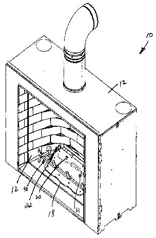
[0031] Referring now to Figures 1 and 2, an example heating appliance in the
form of a
fireplace 10 is shown and described. The exemplary fireplace 10 includes an
outer enclosure
12, a combustion chamber enclosure 14 that defines a combustion chamber 16. A
main
burner 18, a pilot flame assembly 22, a valve 30, a controller 36, a power
supply 38, and first
and second thermistors 40, 42. The main burner 18 includes flame sensors 20,
21 mounted on
a top surface thereof. The pilot flame assembly 22 includes a pilot burner 24,
an ignition
source 26, and a pilot flame sensor 28. The valve 30 includes a pilot valve
contro132, and a
main burner valve contro134. The ignition source 26 can be any device capable
of generating
ignition of the pilot flame.
[0032] The location of the pilot flame assembly 22, valve 30, controller 36,
power
supply 38, main burner flame sensors 20, 21, the pilot flame assembly 22, and
thermistors
40, 42 can be altered in other embodiments. In some configurations, only a
single main
burner flame sensor may be provided and a single thermistor provided in the
combustion
chamber 16, while in other embodiments more than two sensors or thermistors
can be
provided. Further details related to the purpose and function of the various
features of
fireplace 10 is described below with reference to Figures 3-15. The use of
fireplace 10 is
merely exemplary of many different types of heating appliances that can
utilize the
inventive aspects disclosed herein. Heating appliances such as fireplace 10
are especially
useful for providing a decorate flame display within the combustion chamber.
[0033] Generation of a decorative flame can involve some unique issues
compared to
other types of heating appliances wherein a flame or flame display is
irrelevant. For
example, a fireplace heating appliance such as fireplace 10 shown in Figures 1
and 2
includes a relatively large combustion chamber and a corresponding large main
burner
that provides for a sizable flame display which is not generated in a gas
furnace. The
combination of features and the amount of gas flow involved with a gas
fireplace has the
potential for possible aggressive starts of the main burner flame. For
example, in the
-6-
CA 02631725 2008-05-30
WO 2007/070752 PCT/US2006/061596
event the pilot flame assembly does not work properly concurrently with a gas
flow being
supplied to the main burner, a buildup of gas can occur in the combustion
chamber prior
to ignition by the pilot flame assembly. This type of delayed ignition can
result in an
aggressive (higher than normal forces) start that is undesirable and can cause
damage to
the fireplace.
[0034] The example control and monitoring systems disclosed herein provide
improved safety by reducing the likelihood and incidence of undesired delayed
ignitions
and aggressive starts. This can be accomplished in several different ways. One
way is
to perform a status check of system components prior to initiating a start-up
sequence for
the heating application. This status check may be considered a diagnostic or
self-check in
which at least some of the system components (e.g., sensors or other hardware)
are
checked by the system controller/processor to ensure that the component is
operating as
expected and that signals are properly communicated between the components and
the
controller/processor. For example, the system self-checks the components to
confirm proper
voltages, resistance levels, and impedances before proceeding in a start-up
sequence of the
burner. Another way is to restrict a gas flow to the main burner until the
presence of a pilot
flame has been confirmed and preferably a confirmation that the pilot flame is
stabilized.
Further, a main flame can be confirmed at the main burner within a
predetermined time from
when a gas flow is supplied to the main burner. If the main flame is not
detected, the gas
flow can be stopped. In some instances of detected system problems (e.g., lack
of main
flame), the control system is shut down until maintenance can occur. These and
other
features provide improved safety and functionality in a heating appliance.
[0035] Referring now to Figure 3, an example control system 100 is shown
including a
controller 102, a valve 104, a main burner assembly 106, a pilot flame
assembly 108, and an
input device 110. Based on communications from the input device 110, the
control system
102 can communicate with the valve 104, the main burner assembly 106, and
pilot assembly
108 to control ignition of a flame for a heating appliance. The system 100
includes feedback
from the pilot assembly 108 and main burner assembly 106 related to, for
example, ignition
and presence of a flame. This feedback can be used as a check and balance
system to
confirm one or more steps and/or functions involved in igniting the main
burner flame before
proceeding to the next step. In some embodiments, the valve can be configured
with sensors
-7-
CA 02631725 2008-05-30
WO 2007/070752 PCT/US2006/061596
or other devices that provide feedback to the control system to ensure proper
valve function
such as, for example, position of various valve elements that relate to a gas
flow pmvided by
the valve.
[0036] In some embodiments, the system 100 may include multiple valves, main
burner
assemblies, and pilot flame assemblies. These multiple features can be
controlled and
monitored independently. In some embodiments, these multiple features can be
interdependent on each other.
[0037] Referring now to Figure 4, another example control system 200 is shown
and
described. The control system 200 includes a controller 202, a valve 204, a
control pane1210,
a battery backup 212, a remote control unit 214, an AC power supply 216, a
thermistor 218, an
ignition source 220, a pilot flame sensor 222, a main flame sensor 224, a
blower 232, and
lights 234. The system 200 can include a pilot portion 226, a main burner
portion 228, and a
modulator portion 230.
[0038] The control pane1210 may be mounted on a wall or other location that is
remote
from a heating appliance in which other components of the system 200 are
positioned. The
remote control unit 214 can communicate directly with the wall unit 210 or may
be able to
communicate with the controller 202. The remote control unit 214 provides for
control of the
system 200 by a user from a variety of locations without restriction by a
wired system. The
system 200 can include other forms of communication such as those described
below with
reference to Figure 15.
[0039] The battery backup 212 provides a unique DC power backup system that is
described in further detail below in connection with Figure 13. Typically, the
system 200 is
powered by an AC power supply 216 that is coupled directly to the controller
202. The
control pane1210 is typically powered by the AC power supply 216 via the
controller 202, as
are the valve 204, blower 230, lights 234, and other features of the system
200 that require a
power source. In the event that the AC power supply 216 is eliminated (e.g.,
during a power
outage) the battery backup 212 can provide power to not only the control
pane1210 but also
the controller 202 via the control pane1210. This arrangement provides for
positioning of the
battery backup 212 remote from the controller 202, in particular remote from
the heating
appliance itself. Remote positioning of the battery backup 212 eliminates
concerns related to
heat damage accessibility for replacement and other concerns involved when the
battery
-8-
CA 02631725 2008-05-30
WO 2007/070752 PCT/US2006/061596
backup is positioned in close proximity to other features of the heating
appliance (e.g., within
an outer enclosure of a fireplace heating appliance). Additional description
of a similar
battery backup configuration is provided below with reference to Figure 13.
[0040] The controller 202 is capable of bi-directional communication with most
if not all
of the features 218, 220, 222, 224, 230, 234, and 204. In one example, the
controller 202
includes a variety of components as shown in Figure 5. The controller 202 can
include a
CPU 240, memory 242, communications connections 244, a multiplier 246,
removable
storage 248, input devices 250, digital to analog (D/A) converter 252, a power
supply 254,
non-removable storage 256, output devices 258, an analog to digital (A/D)
converter 260,
and a bi-directional serial databus 262. The CPU 240 can be any desired
processor such as a
microprocessor that provides processing and control of information gathered by
the
controller 202. In one example, the CPU is a microprocessor such as the ATMEGA
48V
microprocessor produced by ATMEL Corporation of San Jose, California, which
provides
advantages such as, for example, memory size, cost, power requirements, and
compatibility.
[0041] The memory 242 can be volatile or non-volatile memory for the storage
of various
types of information necessary to operate the controller 202 and other
features of the system
200. The communications connection 244 can be a serial bus connection or other
type of
connection that provides flexibility in the types of components that operate
using controller
202. The removable and non-removable storage 248, 256 can be used to store
different types
of information that may or may not be overwritten, downloaded, or uploaded as
desired. The
input and output devices 250, 258 can include, for example, features of a
communication
system for transmitting and receiving signals via, for example, the
communications
connection 244. The bi-directional serial databus 262 may be a communications
device
separate from the input and output devices 250, 25 8, or may integrated into
one or more of the
devices 250, 258.
[0042] The databus 262 can provide plug-and-play capabilities for the system
200.
Various components of the system 200 can be given identification or data
labels that are
identifiable by the controller 202. When a component is plugged in or
otherwise added to
the system 200 or the heating appliance, two-way communication occurs between
the added
component and the controller 202. The controller is can be preprogrammed to
perform
certain functions and operate in a predetermined way upon receipt of the data
label for that
-9-
CA 02631725 2008-05-30
WO 2007/070752 PCT/US2006/061596
added component or some combination of components coupled to the system.
Similarly,
components already operable on the system can function or operate in a
predetermined way
upon adding a new component that has been identified via the data label and
databus by the
controller. The software or firmware that is run by the CPU 240 of the
controller can be
updated as needed. For example, the software/firmware of the controller 202
can be updated
in view of new components that are to be added to the system 200.
[0043] In one example application of the databus 262 function and the plug-and-
play
functionality of the system 200, a user interface panel (available, for
example, via the input
devices 250) can provide options for control of an ember bed of the fireplace
when the
ember bed has been coupled to the controller 202, but the control options of
the user
interface panel are removed when the ember bed has been removed/decoupled from
the
controller 202. The databus 262 provides communication from the user interface
panel to
the ember bed, and information concerning the ember bed (e.g., whether is
activated and
functioning properly) is communicated from the ember bed back to the user
interface panel
via the databus.
[0044] The D/A and A/D converters 252, 260 in the system 200 or other features
of the
heating appliance. The D/A and A/D converters can also be used to convert
different types
of signals incoming via and outgoing via the input and output devices 250,
258. The power
supply can be, for example, coupled to the AC power supply 216 in the form of,
for
example, a 3 volt AC power supply. The power supply can also be coupled to the
battery
backup 212, wherein the battery backup provides, for example, a DC power
supply using a
standard sized battery (e.g., D battery) that is rechargeable or non-
chargeable.
[0045] The controller 202 can run according to a software code that is loaded
into the
controller memory 242 and operated with the CPU 240. The software code
preferably
provides for monitoring and control of various components of the system 200
such as, for
example, the ignition source 222, pilot and main flame sensors 222, 224,
thermistor 218,
control pane1210, blower 230 and lights 234. The code preferably also provides
for storage
of performance information such as pilot flame and main burner flamer ignition
history, hours
of operation, flame sense signals, lock out history or other maintenance-
related information.
[0046] The controller 202 and system 200 generally can have additional
functions and
features for monitoring and control of a heating appliance as shown and
described in U.S.
-10-
CA 02631725 2008-05-30
WO 2007/070752 PCT/US2006/061596
Patent Application Serial No. 11/238,640, filed on September 28, 2005 and
titled GAS
FIREPLACE MONITORING AND CONTROL SYSTEM, and U.S. Published Patent
Application No. 2005/0208443AI, which patent applications are incorporated
herein by
reference.
[0047] The lights 234 can be used for a variety of purposes including, for
example,
backlighting in a heating appliance as shown and described in U.S. Published
Patent
Application No. 2004/0173202A1, or for providing a simulated electric glowing
ember in a
heating appliance as shown and described in U.S. Patent No. 6,053,165, which
patent
application and patent are incorporated herein by reference. Control of the
lights 234 by the
controller 202 can be correlated with other functions of a heating appliance
and the system
200. For example, modulating the lights 234 can be synchronized with
modulation of a main
burner flame with a modulator 230, or with modulation of a speed of the blower
230.
[0048] The system 200 can, in other embodiments, include additional features
or
multiples of the features illustrated in Figure 4. For example, a plurality of
thermistors 218
and a plurality of main flame sensors 224 can be coupled to the controller 202
to pmvide
additional functionality of the system 200.
[0049] The heating appliance can include visual indicators such as, for
example, one or
more light emitting diodes (LEDs) to convey diagnostic information related to
the heating
appliance. The visual indicators can use color and sequenced ON/OFF operation
to convey
information. Example diagnostics definitions or states that can be
communicated by the
visual indicators include System Abnormal, System Idle, Normal Operation, Cold
Climate
Mode, System Normal, Low Flame Pilot Sense, Low Main Burner Flame Sense,
Failed Pilot
Ignition Trial, Failed Main Burner Ignition Trial, and Hard Lock Out.
[0050] In one example, the diagnostics definitions provided above are
communicated
using a green LED and a red LED. The LEDs can be integrated into a housing of
the
controller or maybe positioned at another location independent of the
controller. In one
example, the LEDs are mounted in a housing of the contmller and the controller
is positioned
within an outer enclosure of a heating appliance. The heating appliance may
include
removable panels or translucent coverings that provide visualization of the
LEDs for purposes
of obtaining the diagnostics information represented by the LEDs. In another
example, the
controller is positioned remotely from the heating appliance such as in a wall
structure or
-11-
CA 02631725 2008-05-30
WO 2007/070752 PCT/US2006/061596
combined with a wall-mounted control panel. In a further example, the LEDs can
be
independently mounted with a wall mounted control panel that is positioned
remotely from
the heating appliance. In a still further example, the LEDs are exposed at a
front panel of the
heating appliance that is exposed for viewing at all times.
[0051] The LEDs can be flashed ON and OFF in different combinations of number
of
flashes, duration and color schemes to communicate the diagnostic information.
For
example, the LED scheme for the OFF mode indicates system idle shown with a
continuous
LED and no flashing, and the LED scheme indicating system normal is that the
red LED is
turned OFF without any flash cycles. With this simple LED scheme, a user or
maintenance
personnel can quickly determine a condition of the system and the heating
appliance by
merely viewing the LEDs. In other embodiments, more or fewer LEDs can be used
with any
desired LED flashing and duration schemes to communicate the necessary
information.
[0052] The controller can provide operation of the heating appliance in a
plurality of
different modes. Some example modes include Off, Pilot Ignition, Mainer Burner
Ignition,
Hard Lock Out, Soft Lock Out, and Self Checks. These six modes are independent
from each
other to the extent that the controller typically operates in only one of the
modes at a given
time. For example, it is preferred to turn OFF the Pilot Ignition Mode prior
to initiating the
Main Burner Ignition Mode. When the controller enters the Hard Lock Out Mode,
the
controller cannot move into another mode until maintenance occurs by a
qualified
maintenance person. In a soft Lock Out Mode, the controller can move into
different modes
if certain actions occur such as, for example, pressing a reset button for the
controller, turning
ON a gas supply to the valve, replacing batteries in the battery backup for
the system, or
restarting the Pilot Ignition Mode.
[0053] Pilot flame sense signals related to monitoring of the pilot flame for
purposes of
the operational modes described above is described with reference to Figures 6
and 7. Figure
6 illustrates a graph in which a pilot flame sense signal is plotted relative
to time. Some
types of ignition systems determine an ON state for the pilot flame when the
pilot flame sense
signal surpassing an ON/OFF threshold level at t] regardless of the future
condition of the
flame sense signal. According to this first configuration, the three signals
A, B, C, which all
surpass the ON/OFF threshold at ti, stabilize at different flame sense levels.
The signal C
stabilizes at a level below the threshold. However, if a pilot flame ON signal
is generated
-12-
CA 02631725 2008-05-30
WO 2007/070752 PCT/US2006/061596
based solely on whether or not the flame sent signal surpasses the threshold
ON/OFF level at
any point, there can be problems with the pilot flame quality that would
prohibit proper
ignition of a main burner flame with a pilot flame represented by signal C.
[0054] An alternative to the first configuration is a configuration in which
the pilot flame
sense signal is monitored at times t2, t3, t4, or at any other time after ti,
in an effort to better
understand the state of the pilot flame before attempting to ignite the main
burner flame.
Such monitoring at additional times can help determine whether the signals A,
B, C stabilize
and the level at which they stabilize.
[0055] Referring now to Figure 7, another configuration for a pilot flame
sense signal
includes a threshold ON/OFF signal level and an upper threshold level above
which an
OKAY flame is defined. A LOW flame is defined between the threshold levels. By
defining
an intermediate LOW flame signal area, it is possible to provide enhanced
maintenance
diagnostics for the pilot flame assembly. For example, the control system can
monitor a
flame sense signal D, which indicates an OKAY pilot flame for ignition of the
main burner
flame. Over time, after multiple uses and startups of the pilot flame, a pilot
flame signal E can
occur, which indicates that the flame is low and that the flames represented
by the signals are
trending towards poor flame conditions. After still further use, a pilot flame
signal F can be
monitored, which indicates at the time ta wherein the signal is stabilized the
signal is below
the ON/OFF threshold. By using this type of graph to monitor and record the
pilot flame
signal over multiple uses of the pilot flame assembly, the controller can
identify trends that
indicate possible future problems with the pilot flame that could be addressed
by
performing maintenance in advance of the problem occurring.
[0056] Figure 7 also illustrates what can be defined as "stabilization" of the
pilot flame
and/or the pilot flame sense signal. Referencing flame sense signal D, it is
common for
the flame (as represented by the flame sense signal) to at first overshoot
desired
stabilization level and then over time oscillate towards the desired
stabilization level (e.g.,
close to zero oscillation at t3). Stabilization of the pilot flame is relevant
for determining
whether the pilot flame will maintain an intensity and quality sufficient to
ignite the main
burner flame when a flow of gas is provided to the main burner. The lower the
stabilization level of the pilot flame (e.g., a LOW flame or below the ON/OFF
threshold
level) the greater the likelihood of ignition problems for the main burner
flame (e.g.,
-13-
CA 02631725 2008-05-30
WO 2007/070752 PCT/US2006/061596
delayed ignition and/or aggressive ignition due to a delay). Further
monitoring of the
flame sense signal after time t3 may be desired in order to confirm that the
pilot flame has
stabilized at a constant rate is not either decreasing or increasing over time
in an adverse
manner.
[0057] Another way of determining whether or not a gas flow should be supplied
to
the main burner based on the pilot flame sense signal is to allow lapse of a
predetermined
amount of time regardless of the stabilization state of the pilot flame so
long as the flame
is above an ON/OFF threshold. In some scenarios, burning the pilot flame for a
certain
amount of time creates heat and energy within the heating appliance to provide
the desired
draft and ignition conditions. With these improved conditions, it may be
possible to
improve the likelihood of proper main burner flame ignition even with a lower
quality,
less stable pilot flame. Thus, in one configuration the gas flow may be
provided to the
main burner at time t4 if the time t4 is adequate to create the desired heat
and energy
conditions even though the flame sense signal may not be fully stabilized.
[0058] Referring now to Figure 8, a graph illustrating a main flame sense
signal is
plotted relative to time. The signal G represents ignition of a main flame
from time ti until
times t2 and t3. Monitoring of the main flame sense signal over time for
multiple startups
along with a comparison of signals can result in useful diagnostic information
for the main
burner. For example over time the main flame sense signal can have delays in
startup as
represented by the series of signals G, H, I, J. This type of delay can
indicate a type of trend
towards lower performance for the main burner.
[0059] In another scenario, the stabilized main flame represented by signals
K, L, M, N
can decrease levels over time, again illustrating possible performance issues
and/or a need for
maintenance for the main burner. A controller can be configured to perform
this type of
monitoring and analysis of stored data that has been gathered over time. The
controller can
also be configured to generate notices, reports, or other signals notifying a
user or
maintenance personnel of the need for maintenance and/or repair of certain
aspects of the
main burner, sensors, associated with the burner, etc.
1. Example Pilot Flame Sense Monitoring
[0060] The pilot flame sense is monitored from the initiation of the Pilot
Ignition Mode
-14-
CA 02631725 2008-05-30
WO 2007/070752 PCT/US2006/061596
through the Main Burner Ignition Mode, in a soft lock out mode, and during
soft checks until
the OFF mode is again initiated. The pilot flame sense should be above a
threshold drop-out
level. Preferably, the pilot flame sense is greater than four times nominal
drop out threshold.
If the flame sense stabilizes less than two times the nominal drop out
threshold, operation is
continued and a diagnostic signal is generated. When the pilot flame sense
stabilizes above
two times drop out threshold, the diagnostic signal is terminated.
[0061] The pilot flame sense should vary less than 10% for at least two
seconds before
initiation of the Main Burner Ignition Mode. If the pilot flame sense is above
the drop out
threshold but varies greater than 10% for ten seconds, operation proceeds and
a diagnostic
signal is generated. If the pilot flame sense varies less than 10%, for two
seconds, the
diagnostic signal is terminated. Once the pilot flame sense stabilizes the
operation sequence
proceeds to the main burner mode. If the pilot flame sense does not stabilize
above the drop
out threshold after 45 seconds, the pilot ignition sequence is terminated and
another
diagnostic signal is generated.
[0062] With the ignition sequence terminated, the Pilot Ignition Mode can be
manually
initiated again by changing system state from ON to OFF and back to ON again.
The pilot
ignition will be automatically initiated again after a 15 minute delay for a
total of three
ignition tries. After three failed automatic pilot ignition trials the soft
lock out mode is
initiated. The diagnostic signal terminates only upon a successful pilot
ignition.
II. Example Main Burner Flame Sense Monitoring
[0063] The main burner flame sense is monitored from the initiation of the
main burner
ignition through the sequence of modes to either the OFF mode or a Cold
Climate Mode if a
Cold Climate Mode (see below) is initiated. The main burner flame sense is
preferably
above a drop out threshold. The main burner flame sense is preferably greater
than four
times a nominal drop out threshold. The main burner flame sense stabilizes
less than two
times a normal drop out threshold, operation continues and a diagnostic signal
is sent. When
the main burner flame sense stabilizes above two times the drop out threshold,
the diagnostic
signal can be terminated. The main burner flame sense should occur within 10
seconds of
opening a main burner valve. If the main burner flame sense does not occur
within 10
seconds of opening the main burner valve, the main burner valve is closed and
the pilot
-15-
CA 02631725 2008-05-30
WO 2007/070752 PCT/US2006/061596
operation mode continues with another diagnostic signal being sent. After the
main valve
has been closed, the pilot mode operates continuously and the pilot flame
sense is monitored
until a successful main burner ignition occurs.
[0064] Any time during a main burner ignition time out period (i.e., the main
valve
closing after 10 seconds of no main burner flame sense) if the pilot flame
sense is not stable
and greater than two times nominal drop out threshold the system goes into a
hard lock out
mode and a diagnostic signal is sent. If the pilot flame sense is stable, the
Main Burner
Ignition Mode can be manually initiated by cycling the control from ON to OFF
and ON
again. Retries will not be allowed to occur less than 5 minutes apart after
the first failed
main burner ignition trial.
111. Example Normal Heating appliance Operation
[0065] Normal heating appliance operation is initiated by either a heating
appliance ON
command being received at the serial bus of the controller or wires of the
system are shorted
(e.g., 3 volts DC continuous on one of the com ports). An exmaple normal
heating appliance
operation is defined according to the following steps:
a. Initiate self checks
b. Initiate pilot ignition
c. Monitor pilot flame sense
d Initiate main burner ignition
e. Monitor main burner flame sense.
[0066] Normal operation is terminated by either heating appliance OFF command
being
received at the serial bus. The normal operation terminates if a Cold Climate
Mode is not
active and the system returns to OFF mode, or if the Cold Climate Mode is
active the main
valve is turned OFF and the Cold Climate Mode continues.
[0067] A variation of the normal heating appliance operation is illustrated in
the flow
diagram of Figure 9. Figure 9 illustrates a step 300 of the user turning ON
the heating
appliance at a control panel, a step 302 of the signal being sent from the
control pane to the
controller, a step 304 of the controller checking the status of the pilot
burner, a step 306 of the
controller checking a status of the main burner, a step 308 of the controller
turning ON the
pilot valve, and a step 310 of the controller turning ON the ignition source
generator to ignite
-16-
CA 02631725 2008-05-30
WO 2007/070752 PCT/US2006/061596
the pilot burner. The operation further includes a step 312 of the controller
monitoring the
pilot flame to ensure stability, a step 314 of the controller turning ON the
main burner valve,
and a step 316 of the controller monitoring the main burner flame to ensure
startup.
[0068] The step 306 of checking the status of the main burner can occur
concurrently
with other steps 302, 304, 308, 310, 312, 314. For example, the system may
continuously
check the status of the main burner at all times to ensure that the main
burner is either OFF or
ON at the proper time or else a lock out of the system can occur.
[0069] Another example heating appliance operation is illustrated with
reference to Figure
10. In a step 400 the user turns ON the heating appliance at a control panel,
and in a step 402
the controller checks status of the pilot burner. If the pilot burner is not
ON, the controller
turns ON the pilot valve in a step 404, and in a step 406 the controller turns
ON the pilot
ignition source and checks for a pilot flame. In some embodiments, a separate
step of
checking the status of the main burner is performed prior to steps 404, 406.
If the main
burner is already in operation, there is no typically no need to ignite the
pilot flame.
[0070] If a pilot flame is present, the controller monitors the pilot flame to
determine
whether the pilot flame is stabilized in a step 410 and if it is stabilized
the controller turns ON
the main burn valve in a step 412. The controller then determines the presence
of a main
flame in step 414 and if a main flame exists, the controller monitors the main
flame in a step
418. If the controller does not determine the main flame, the controller turns
OFF the main
burner valve in a step 416 and there is a repeat of steps 410, 412, 414. In
the step 406
wherein the pilot flame is not present, the controller turns OFF the pilot
valve in a step 408
and the step 402 is repeated. If the pilot flame is not stabilized in the step
410, the controller
again turns OFF the pilot valve and the step 402 is repeated.
IV. Example Cold Climate Mode Operation
[0071] A Cold Climate Mode can be used to improve draft of the heating
appliance and
to improve efficiency and startup capabilities. Cold Climate Mode involves
running the
pilot flame for a predetermined amount of time that is longer than the normal
time periods of
to the Pilot Ignition Mode in advance of initiating the Main Burner Ignition
Mode. Running
of the pilot flame heats up the area in the heating appliance and causes a
draft out of the
heating appliance exhaust pipe so that when the main burner flame is ignited,
the exhaust
-17-
CA 02631725 2008-05-30
WO 2007/070752 PCT/US2006/061596
gases automatically flow out of the combustion chamber of a heating appliance.
There is
typically a balance in efficiencies between running the pilot flame to create
the desired draft
and ensuring that the heating appliance maintains optimum efficiency. Thus,
the Cold
Climate Mode is preferably controlled with time restraints that provide the
desired draft
generating results while burning the pilot flame a minimum amount of time to
increase
efficiency.
[0072] The Cold Climate Mode is initiated by either a "pilot" command received
at the
serial bus of the controller, a temperature of the system thermistor is below
a predetermined
amount, or the thermistor is shorted (-0 ohms detected). The Cold Climate Mode
is only
active when there is no demand for the main burner. Beginning at the OFF mode,
the Cold
Climate Mode first initiates self checks, initiates Pilot Ignition Mode and
monitors the pilot
flame sense. From the normal heating appliance operation, when the normal
heating
appliance operation is terminated, the pilot operation is maintained. When
going from Cold
Climate Mode to a normal heating appliance operation, the normal heating
appliance
operation is initiated and execution of the ignition sequence from the main
burner ignition
occurs. Cold Climate Mode termination occurs if there is no main burner
ignition demand
and none of the Cold Climate Mode initiation criteria are valid, thus the
pilot operation is
terminated.
[0073] Figure 11 illustrates an example method for use of a Cold Climate Mode.
In a step
500, it is determined if a Cold Climate Mode criteria is met. If the criteria
is met and a step
504 of the cold climate control mode is activated. If the criteria are not
met, the system
maintains normal operating mode in a step 502. After the cold climate control
mode is
activated, in a step 506 ignition and/or maintenance of the pilot flame
occurs. In a step 508,
there is a check to see if the heating appliance is turned on. If it is not
turned on, then step
506 is repeated. If it is turned on, the Cold Climate Mode is deactivated in a
step 510, and in
a step 512 the main burner valve is opened and the main burner is operated for
a desired time
period until the heating appliance is turned OFF in a step 514.
V. Example Stove Timer Mode Operation
[0074] A Stove Timer Mode can be used in operation of a stove style heating
appliance.
Stoves sometimes have more common problems with generating a proper draft than
other
-18-
CA 02631725 2008-05-30
WO 2007/070752 PCT/US2006/061596
types of heating appliances, such as a fireplace. The stove timer is used to
delay the
initiation of the main burner ignition after start up of the pilot flame when
the stove has not
been used for a predetermined time such as, for example, three or more days.
The stove tinier
automatically places the system in Cold Climate Mode for three days after the
stove has been
used in order to maintain a certain temperature in the stove and to maintain a
draft.
[0075] The following is an example stove startup sequence using a Stove Timer
Mode:
= After the Pilot Ignition Mode is completed, the delay timer is started.
= The Main Burner Ignition Mode is initiated after the delay timer
reaches 5 minutes.
= The stove operational sequence continues normally.
= When stove operation is terminated, the system remains in Cold
Climate Mode and the stove timer is initiated.
= If stove operation is initiated before the stove timer equals 3 days, the
ignition sequence begins at main burner ignition.
= At determination of each stove operation cycle, the stove timer is
reset.
= If the Cold Climate Mode time of operation reaches 3 days with no
stove operation initiated, the system terminates Cold Climate Mode
and returns to OFF Mode.
[0076] The use of a 5 minute delay between pilot ignition and main burner
ignition helps
to ensure creation of a draft in the stove. The 3 day operation of the Cold
Climate Mode after
the stove operation is terminated helps maintain the stove in a ready-to-
operate condition
during a time period in which it can be more likely that the user will again
use the stove.
Other time periods for the delay and the cold climate operation time are
possible. For
example, the delay time can be about 1 to about 30 minutes, more preferably
about 1 to about
10, and most preferably about 3 to about 6 minutes. The cold climate operation
can be about
0.5 days to about 10 days, more preferably about 1 day to about 5 days, and
most preferably
about 2 to about 3 days.
[0077] Figure 12 illustrates steps of a method related to the Stove Timer
Mode. In a step
600, the heating appliance is turned on, followed by step 602 which the pilot
flame is ignited, a
step 604 in which there is a delay for a first predetermined time period
before opening a main
-19-
CA 02631725 2008-05-30
WO 2007/070752 PCT/US2006/061596
burner valve. After the main burner valve is opened, the main burner is
operated for a desired
time period in a step 606 and in a step 608 the heating appliance is turned
off. After turning
OFF the appliance, in a step 610 the pilot flame is maintained ON for a second
predetermined
time period and there is a check during the second predetermined time period
for the heating
appliance being turned ON in a step 612. If the heating appliance is turned
on, the step 606
is repeated. If the heating appliance is not turned ON during the second
predetermined time
period, the pilot flame is shut OFF in a step 614.
VI. Example Battery Backup Operation
[0078] Referring not to Figure 13, a flow diagram illustrating the use of the
back of
battery pack in a heating appliance control system (e.g., battery backup 212
shown in Figure 4)
is shown and described. The method includes providing an AC power supply to
the
controller in a step 700 and concurrently positioning a battery backup pack
with a control
panel that is located outside the heating appliance in a step 702. If AC power
is available in
a step 704, the controller is operated using AC power in a step 706. If AC
power is not
available, there is a step of electrically connecting the battery pack to the
controller through
the control panel in step 708 and operating the controller using DC power from
the battery
pack in a step 710. In accordance with this method, it is possible to position
the backup
battery pack outside of the heating appliance. It is also possible according
to this
configuration to power a wall mounted control panel using the battery pack and
further
operates the controller with the battery pack by routing DC power from the
battery pack
through the control panel to the controller.
VII. Example Diagnostics Operation
[0079] Referring now to Figure 14, a process flow diagram illustrating a
possible method
for obtaining diagnostic information for maintenance purposes in a heating
appliance is
shown and described. In a step 800, there is provided a heating appliance
having a
controller, a pilot flame system, and a main flame burner. In a step 802,
there is operation of
the pilot flame system for a plurality of ON/OFF cycles and a concurrent step
804 of operating
a main flame burner for a plurality of ON/OFF cycles. In a step 806,
evaluation of
performance trends in the pilot flame system and main flame system occurs
followed by a
step 808 in which it is determined whether trends correlate to a required
maintenance. If the
-20-
CA 02631725 2008-05-30
WO 2007/070752 PCT/US2006/061596
trends do correlate to a required maintenance, a step 810 occurs in which the
maintenance/service requirement is reported. If the trends do not correlate to
required
maintenance, a step 812 includes continued operation of the heating appliance.
In other
configurations, the step 806 can be broken into separate steps of evaluating
the pilot flame
system and the main flame burner and conducting separate steps to determine
whether
maintenance is required.
VIII. Example Communications System
[0080] Figure 15 illustrates a system 900 that provides for communication
between a
heating appliance control system 902 and a maintenance person/device 906 or
remote
database 908 via a communication network 904. The heating appliance control
system can
include a plurality of sensors (not shown) and a controller/processor (not
shown) that provide
communication of information about a heating appliance performance and
conditions. The
communications network 904 can be any desired communication system. Some
example
communication systems include radial frequency (RF), infrared (IR), cellular,
satellite,
ultrasound, optics, drawn wire, or any other wireless or wired communication
systems. One
example digital means of communication includes the use of a modem wherein the
communication signals between the heating appliance control system 902 and
remote
database 908 are delivered via a telephone or cable wired communication
network. Other
example digital means of communication include cellular and satellite means of
communication. Some example analog means of communication include, for
example, direct
AC/DC and POT (plain old telemetry) systems.
[0081] The heating appliance control system 902 can include a connector for
future add-
on sensors that can go to different ports of a microcontroller such as I/O's,
A/D or D/A
converter lines. The system can also include the capability (e.g., via a
serial port) for a service
technician to retrieve the history of the heating appliance's actions and/or
problems from the
microcontroller or communication transmission. Such capability can also
include the
possibility for future upgrades in code and a possibility of talking with
another
microcontroller that could be in an add-on device in the future. The system
can use LEDs as
status indicators on the heating appliance, at other locations in close
proximity to the heating
appliance, or at the remote computer location. These visual indicators can be
turned OFF or
-21-
CA 02631725 2008-05-30
WO 2007/070752 PCT/US2006/061596
removed according to user preferences.
[0082] The examples provided above with reference to the attached Figures
focus on gas
burning decorative heating appliances such as fireplaces, stove, and fireplace
inserts. The
systems and methods described above could be modified to provide the same or
similar
functions for other types of decorative heating appliances such as, for
example, electric, wood
burner, and pellet fireplaces, stove and fireplace inserts. While such
alternative heating
appliances may not include a valve or the type of ignition system required for
ignition of a
gaseous fuel, such alternative heating appliances can include different types
of ignition
systems and heat sources that can be monitored and controlled with the
assistance of sensors,
as well as blowers, light fixtures, air filters, scent generating devices and
other features that
can be monitored and controlled. For example, the system can include sensors
that monitor
the fuel supply associated with the decorative heating appliance. For example,
a sensor or
other monitoring device can be used to monitor a pellet supply level for a
pellet stove or
fireplace, or a liquid propane (LP) supply level for a LP gas fireplace.
[0083] The present invention should not be considered limited to the
particular examples
or materials described above, but rather should be understood to cover all
aspects of the
invention as fairly set out in the attached claims. Various modifications,
equivalent
processes, as well as numerous structures to which the present invention may
be applicable
will be readily apparent to those of skill in the art to which the present
invention is directed
upon review of the instant specification.
-22-