Language selection

Search

Patent 2632060 Summary

Third-party information liability

Some of the information on this Web page has been provided by external sources. The Government of Canada is not responsible for the accuracy, reliability or currency of the information supplied by external sources. Users wishing to rely upon this information should consult directly with the source of the information. Content provided by external sources is not subject to official languages, privacy and accessibility requirements.

Claims and Abstract availability

Any discrepancies in the text and image of the Claims and Abstract are due to differing posting times. Text of the Claims and Abstract are posted:

  • At the time the application is open to public inspection;
  • At the time of issue of the patent (grant).
(12) Patent Application: (11) CA 2632060
(54) English Title: MANUAL GANGWAY FOR A BOAT
(54) French Title: PASSERELLE MANUELLE POUR BATEAU
Status: Deemed Abandoned and Beyond the Period of Reinstatement - Pending Response to Notice of Disregarded Communication
Bibliographic Data
(51) International Patent Classification (IPC):
  • B63B 27/14 (2006.01)
(72) Inventors :
  • GRIMALDI, MICHELE (Italy)
(73) Owners :
  • OPACMARE S.P.A.
(71) Applicants :
  • OPACMARE S.P.A. (Italy)
(74) Agent: MACRAE & CO.
(74) Associate agent:
(45) Issued:
(86) PCT Filing Date: 2006-04-28
(87) Open to Public Inspection: 2006-11-16
Availability of licence: N/A
Dedicated to the Public: N/A
(25) Language of filing: English

Patent Cooperation Treaty (PCT): Yes
(86) PCT Filing Number: PCT/IB2006/051340
(87) International Publication Number: IB2006051340
(85) National Entry: 2008-05-27

(30) Application Priority Data:
Application No. Country/Territory Date
05425301.8 (European Patent Office (EPO)) 2005-05-06

Abstracts

English Abstract


A manual gangway (1) for a boat (S) comprises a proximal gangway element (2)
and a distal gangway element (3) which define a passage surface (P) for the
transit of persons. The proximal gangway element (2) is provided at a proximal
end (4b) with a connection device (22, 24) which allows the gangway to be
removably assembled to the boat. The gangway elements each comprise a support
element (4, 5), consisting of a profile of box-like section, and a respective
panel (6, 7) above it forming said passage surface. Each support element and
respective panel are assembled in such a way that the support element is
located along the centre line of the respective panel, when seen in plan view.
The support element (7) of the distal gangway element (3) can slide inside the
support element (6) of the proximal gangway element (4) in such a way as to
give rise to a telescopic-extension configuration.


French Abstract

Passerelle manuelle (1) pour bateau (S) qui comprend un élément proximal (2) et un élément distal (3) définissant une surface de passage (P) pour les personnes. L'élément (2) se trouve à une extrémité proximale (4b) avec un dispositif de connexion (22, 24), permettant un assemblage libérable sur le bateau. Les deux éléments comprennent un support (4, 5) à profil ayant une section en forme de caisson, et un panneau respectif (6, 7) au-dessus du support pour constituer la surface de passage. Chaque support et chaque panneau sont assemblés de sorte que le support se trouve le long de la ligne centre du panneau correspondant, selon une vue en plan. Le support (7) de l'élément (3) peut coulisser à l'intérieur du support (6) de l'élément (4) pour donner une configuration en extension télescopique.

Claims

Note: Claims are shown in the official language in which they were submitted.

CLAIMS
1. Manual gangway (1) for a boat (S), comprising a proximal
gangway element (2) and a distal gangway element (3) which
define a passage surface (P) for the transit of persons,
wherein said proximal gangway element (2) is provided at a
proximal end (4b) with connection means (22, 24) which allow
the gangway to be removably assembled to the boat, and
wherein said gangway elements each comprise a support element
(4, 5), consisting of a profile of box-like section, and a
respective panel (6, 7) above it forming said passage
surface, said support element and respective panel being
assembled in such a way that the support element is located
along the centre line of the respective panel, when seen in
plan view,
characterized in that the support element (7) of the
distal gangway element (3) can slide inside the support
element (6) of the proximal gangway element (4) in such a way
as to give rise to a telescopic-extension configuration.
2. Gangway according to Claim 1 in which the support element
(4) and the panel (6) of the proximal gangway element (2) are
assembled in a spaced relationship, and the support element
(5) and the panel (7) of the distal gangway element (3) are
also assembled in a spaced relationship, in such a way that
the distal panel (7) can slide between the proximal support
element (4) and the proximal panel (6).
3. Gangway according to Claim 1 or 2 in which a roller (17),
which can rotate about a pin (18) mounted in such a way as to
connect side walls of the distal support element (5), is
mounted at the distal end (5a) of the distal support element
(5).
4. Gangway according to one of Claims 1 to 3, in which said
connecting means comprise a fork element (22), to which said
proximal support element (4) is pivoted, said fork element

6
having a shaft portion (24) which can be inserted removably
in a corresponding seat (25) provided on the boat (S).
5. Gangway according to one of Claims 1 to 4, in which a
releasable stop device (31), which can selectively immobilize
the distal support element (5) in a certain position of
emergence, is also mounted on the proximal support element
(4).
6. Gangway according to one of the preceding claims, in
which fastening means (32) for fastening the gangway (1) with
a traction cable are provided on said at least one gangway
element (2).

Description

Note: Descriptions are shown in the official language in which they were submitted.


CA 02632060 2008-05-27
WO 2006/120598 PCT/IB2006/051340
1
Manual gangway for a boat
The present invention relates to a manual gangway.for a boat,
comprising a proximal gangway element and a distal gangway
element which define a passage surface for the transit of
persons,' wherein said proximal gangway element is provided at
a proximal end with connection means which allow the gangway
to be removably assembled to the boat, and wherein said
gangway elements each comprise a support element, consisting
of a profile of box-like section, and a respective panel
above it forming said passage surface, said support element
and respective panel being assembled in such a way that the
support element is located along the centre line of the
respective panel, when seen in plan view.
So-called manual gangways are known which are generally used
on small boats or for occasional use. So that they can be
handled and transported manually, such gangways are generally
lightweight and easy to use. Conventional manual gangways
generally consist of a single gangway element or a pair of
elements mounted so as to form a folding structure. Each
element is generally formed of a pair of lateral profiles,
connected by an intermediate panel which provides a passage
surface for the transit of persons. A manual gangway of the
type defined at the beginning is instead described in SU 366
117 A.
The manual gangway according to the invention is
characterized in that the support element of the distal
gangway element can slide inside the support element of the
proximal gangway element in such a way as to give rise to a
telescopic-extension configuration.
Particular embodiments of the invention are defined in the
dependent claims.

CA 02632060 2008-05-27
WO 2006/120598 PCT/IB2006/051340
2
A preferred but non-limiting embodiment of the invention will
now be described with reference to the attached drawings, in
which:
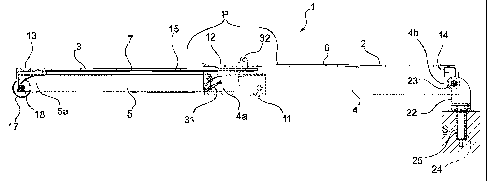
- Figure 1 is a plan view from below of a manual gangway for
a boat according to the invention;
- Figure 2 is a view in side elevation of the gangway of
Figure 1; and
- Figure 3 is a view in section of the gangway of Figure 1,
taken along the line III-III of said figure.
With reference to the figures, these show a gangway 1
according to the invention which can be assembled to a boat
S, comprising a pair of proximal and distal elongate gangway
elements 2, 3 which define a surface P for the passage of
persons between a boat S (part of which is shown in Figure 2)
and a mooring structure, for example a jetty (not shown). In
the present description, the terms proximal and distal are
used with reference to the point of assembly of the gangway 1
to the boat S.
Each gangway element 2, 3 comprises a support element 4, 5,
respectively, on which is mounted a panel 6, 7 which forms
the passage surface P. Seen in a plan view, the support
elements 4 and 5 are located along the centre line of the
respective panels 6 and 7. The support elements 4, 5 consist
of profiles made of lightweight material, for example
aluminium, having a box-like section, for example square. The
support elements 4, 5 are arranged so as to form a telescopic
structure, which can extend in a known manner to reach a
predefined maximum length of extension.
In particular, the distal support element 5 can slide inside
the proximal support element 4. To this end, the distal
support element 5 has a smaller section than the section of
the opening defined by the profile of the proximal support
element 4. To keep the two box-like elements 4 and 5 aligned,
sliding blocks 9, made of a material which is resistant to

CA 02632060 2008-05-27
WO 2006/120598 PCT/IB2006/051340
3
wear from sliding, are mounted on the outside of the walls of
the distal element 5 and/or on the inside of the walls of the
proximal element 4. To prevent the distal element 5 from
sliding out all the way, a stop member 11 is provided on at
least one of the walls of the profile of the proximal
element, near the distal end 4a of the proximal element 4. At
least one of the sliding blocks 9 comes up against this stop
member 11 at the point of maximum emergence of the distal
element 5.
The panels 6, 7 are also made of a lightweight material, for
example a composite material, wood, aluminium, etc. and may
have a frame (not shown) . Head elements 12 and 13, which
rigidly connect the respective support element 4 and 5 to the
panel 6 and 7 above, are mounted at the distal end 4a and 5a
of the support elements 4 and S. A transverse element 14,
consisting of a profile having a U-section, for example made
of aluminium, is mounted at the proximal end 4b of the
proximal support element 4, and this transverse element
rigidly connects the support element 4 to the panel 6 located
above. A sliding sheet 15, mounted on the distal element 5,
is placed between the distal support element 5 and the panel
7 above. The U-section 14 and the proximal head element 12
act as a spacer between the proximal support element 4 and
the panel 6 above. At the same time, the distal head element
13 acts as a spacer between the distal support element 5 and
the panel 7 above, while the sliding sheet 15 provides a
surface for bearing against the proximal support element 4.
In this way, as the distal element 5 emerges from the
proximal element 4, the panel 7 can slide between the upper
wall of the profile of the proximal support element 4 and the
panel 6, sliding via the sliding sheet 15 in contact with
this wall.
A roller 17, which can rotate about a pin 18 mounted in such
a way as to connect the side walls of the profile of the
distal support element 5, is also mounted at the distal end

CA 02632060 2008-05-27
WO 2006/120598 PCT/IB2006/051340
4
5a of the distal support element 5. This roller 17 allows the
gangway 1 to rest on a mooring structure of the boat S
without rubbing.
A fork element 22, on whose arms is mounted a pin 23, is
mounted at the proximal end 4b of the proximal support
element 4. The proximal support element 4 is mounted
rotatably on the pin 23. The fork element 22 has a shaft
portion 24 which can be inserted removably in a corresponding
seat 25 provided on the boat S, for example by means of a
bayon&t coupling device 26.
Preferably, a releasable stop device 31, for example a
ratchet, which can immobilize the distal support element 5 in
a certain position of emergence, is also mounted on the
proximal support element 4.
Preferably, fastening devices 32, for example eye bolts, for
fastening the gangway 1 with a traction cable (not shown),
are also provided on the head element 12 of the proximal
gangway element 2.
As can be seen, the manual gangway according to the invention
can have a very limited weight, in particular when the
materials and the thickness of the walls of the profiles of
box-like section are judiciously selected. It may therefore
be easily removed manually from its seat after use and stored
even in small spaces.
It is understood that the embodiment described herein is to
be interpreted as an exemplary embodiment of the invention;
the invention can however be modified in terms of the form
and arrangement of parts, and constructional and operational
details, in accordance with the many possible variants deemed
appropriate by those skilled in the art.

Representative Drawing
A single figure which represents the drawing illustrating the invention.
Administrative Status

2024-08-01:As part of the Next Generation Patents (NGP) transition, the Canadian Patents Database (CPD) now contains a more detailed Event History, which replicates the Event Log of our new back-office solution.

Please note that "Inactive:" events refers to events no longer in use in our new back-office solution.

For a clearer understanding of the status of the application/patent presented on this page, the site Disclaimer , as well as the definitions for Patent , Event History , Maintenance Fee  and Payment History  should be consulted.

Event History

Description Date
Application Not Reinstated by Deadline 2011-04-28
Time Limit for Reversal Expired 2011-04-28
Deemed Abandoned - Failure to Respond to Maintenance Fee Notice 2010-04-28
Letter Sent 2009-05-14
Reinstatement Requirements Deemed Compliant for All Abandonment Reasons 2009-04-30
Deemed Abandoned - Failure to Respond to Maintenance Fee Notice 2009-04-28
Inactive: Cover page published 2008-09-11
Inactive: Notice - National entry - No RFE 2008-09-09
Inactive: First IPC assigned 2008-06-28
Application Received - PCT 2008-06-27
National Entry Requirements Determined Compliant 2008-05-27
Application Published (Open to Public Inspection) 2006-11-16

Abandonment History

Abandonment Date Reason Reinstatement Date
2010-04-28
2009-04-28

Maintenance Fee

The last payment was received on 2009-04-30

Note : If the full payment has not been received on or before the date indicated, a further fee may be required which may be one of the following

  • the reinstatement fee;
  • the late payment fee; or
  • additional fee to reverse deemed expiry.

Patent fees are adjusted on the 1st of January every year. The amounts above are the current amounts if received by December 31 of the current year.
Please refer to the CIPO Patent Fees web page to see all current fee amounts.

Fee History

Fee Type Anniversary Year Due Date Paid Date
MF (application, 2nd anniv.) - standard 02 2008-04-28 2008-05-27
Basic national fee - standard 2008-05-27
Reinstatement (national entry) 2008-05-27
MF (application, 3rd anniv.) - standard 03 2009-04-28 2009-04-30
Reinstatement 2009-04-30
Owners on Record

Note: Records showing the ownership history in alphabetical order.

Current Owners on Record
OPACMARE S.P.A.
Past Owners on Record
MICHELE GRIMALDI
Past Owners that do not appear in the "Owners on Record" listing will appear in other documentation within the application.
Documents

To view selected files, please enter reCAPTCHA code :


To view images, click a link in the Document Description column (Temporarily unavailable). To download the documents, select one or more checkboxes in the first column and then click the "Download Selected in PDF format (Zip Archive)" or the "Download Selected as Single PDF" button.

List of published and non-published patent-specific documents on the CPD .

If you have any difficulty accessing content, you can call the Client Service Centre at 1-866-997-1936 or send them an e-mail at CIPO Client Service Centre.

({010=All Documents, 020=As Filed, 030=As Open to Public Inspection, 040=At Issuance, 050=Examination, 060=Incoming Correspondence, 070=Miscellaneous, 080=Outgoing Correspondence, 090=Payment})


Document
Description 
Date
(yyyy-mm-dd) 
Number of pages   Size of Image (KB) 
Description 2008-05-26 4 183
Drawings 2008-05-26 3 48
Claims 2008-05-26 2 61
Abstract 2008-05-26 1 67
Representative drawing 2008-09-10 1 9
Notice of National Entry 2008-09-08 1 194
Courtesy - Abandonment Letter (Maintenance Fee) 2009-05-13 1 172
Notice of Reinstatement 2009-05-13 1 163
Courtesy - Abandonment Letter (Maintenance Fee) 2010-06-22 1 171
Reminder - Request for Examination 2010-12-29 1 119
PCT 2008-05-26 3 109
Fees 2009-04-29 1 26