Language selection

Search

Patent 2632252 Summary

Third-party information liability

Some of the information on this Web page has been provided by external sources. The Government of Canada is not responsible for the accuracy, reliability or currency of the information supplied by external sources. Users wishing to rely upon this information should consult directly with the source of the information. Content provided by external sources is not subject to official languages, privacy and accessibility requirements.

Claims and Abstract availability

Any discrepancies in the text and image of the Claims and Abstract are due to differing posting times. Text of the Claims and Abstract are posted:

  • At the time the application is open to public inspection;
  • At the time of issue of the patent (grant).
(12) Patent: (11) CA 2632252
(54) English Title: SURFACE-MOUNTED POST BASE
(54) French Title: BASE DE POTEAU MONTEE A LA SURFACE
Status: Deemed expired
Bibliographic Data
(51) International Patent Classification (IPC):
  • E04H 12/22 (2006.01)
  • E01F 9/615 (2016.01)
  • E01F 9/631 (2016.01)
(72) Inventors :
  • SALMAN, MARK T. (United States of America)
(73) Owners :
  • SALMAN, MARK T. (United States of America)
(71) Applicants :
  • SALMAN, MARK T. (United States of America)
(74) Agent: OSLER, HOSKIN & HARCOURT LLP
(74) Associate agent:
(45) Issued: 2011-11-01
(22) Filed Date: 2008-05-23
(41) Open to Public Inspection: 2008-12-20
Examination requested: 2008-05-23
Availability of licence: N/A
(25) Language of filing: English

Patent Cooperation Treaty (PCT): No

(30) Application Priority Data:
Application No. Country/Territory Date
11/812,590 United States of America 2007-06-20

Abstracts

English Abstract

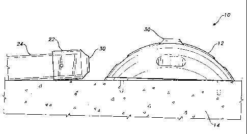
A surface-mounted base for a breakaway signpost. The base is configured as a sphere so as to present no edges that may be impacted by a vehicle and includes a sunken socket ensuring that no metal shards project above grade after a post is damaged. The base is provided with recessed slots for retaining securing bolts therein. This arrangement prevents the securing bolt heads from being contacted by the undercarriage of a vehicle or mower and plow blades of maintenance machines. The slots also allow for rotation of the base during installation ensuring correct orientation of the signpost. Reflective or florescent materials can be attached to the recesses to enhance night visibility.


French Abstract

Base de poteau montée à la surface et à caisson de sécurité. La base est de forme sphérique afin de ne présenter aucun rebord pouvant faire impact avec un véhicule, et comprend une douille évidée pour assurer qu'aucun tesson métallique ne soit projeté en élévation lorsque le poteau a été endommagé. La base est munie de fentes évidées pour y retenir les boulons de fixation. Cette disposition empêche les têtes des boulons de fixation de toucher le dessous de carrosserie d'un véhicule ou d'une tondeuse et les lames de charrues des machines d'entretien. Les fentes permettent également la rotation de la base lors de son installation, ce qui permet d'assurer la bonne orientation du poteau d'indication. Des matériaux réfléchissants ou fluorescents peuvent être fixés aux évidements afin d'améliorer la visibilité du panneau de nuit.

Claims

Note: Claims are shown in the official language in which they were submitted.


CLAIMS:


1. A surface-mounted base, for a breakaway signpost comprising:
a base member configured as a hemisphere, said base member having a planar
bottom surface, a curved upper surface and a perimeter;
an opening forming a socket disposed in a central area of said curved upper
surface;
a bottom wall having a solid surface, disposed in said socket, said bottom
wall
having a continuously sloping planar surface, wherein a bottom surface of the
signpost
does not extend beyond the surface of the bottom wall;
breakaway structure for supporting the signpost disposed in said opening
forming a socket;
a plurality of recesses spaced around said perimeter;
an array of slots formed through said planar bottom surface; and
a bolt disposed in each slot of said array.

2. A surface-mounted base, for a breakaway signpost comprising:
a base member configured as a hemisphere, said base member having a planar
bottom surface, a curved upper surface and a perimeter;
a substrate, said substrate having an upper surface, said base member attached

to said upper surface of said substrate;
an opening forming a socket disposed in a central area of said curved upper
surface;
a bottom wall having a solid surface, disposed in said socket, said bottom
wall
having a continuously sloping planar surface, wherein a bottom surface of the
signpost
does not extend beyond the surface of the bottom wall;
breakaway structure for supporting the signpost disposed in said opening
forming a socket;
a plurality of recesses spaced around said perimeter;
an array of slots formed through said planar bottom surface; and
a plurality of bolts for attaching said base member to said substrate.

3. The surface-mounted base for a signpost according to claim 2, wherein
each bolt of said plurality of bolts is received in a respective slot of said
array of slots.


6

4. The surface-mounted base for a signpost according to claim 1 or 2,
wherein each slot of said array of slots is disposed in a respective recess of
said
plurality of recesses.

5. The surface-mounted base for a signpost according to claim 1, 2 or 4,
wherein each slot of said array of slots is a radial slot.

6. The surface-mounted base for a signpost according to claim 2, wherein
at least one passage for a setscrew extends into said opening forming said
socket.

Description

Note: Descriptions are shown in the official language in which they were submitted.


CA 02632252 2011-03-17

SURFACE-MOUNTED POST BASE

The present invention generally relates to support structure. More
specifically, the
present invention is drawn to a support member for a breakaway post assembly.

BACKGROUND ART

The ubiquitous signpost appears to be a permanent fixture in modern societies.
The
signposts are employed to support traffic signals, traffic warnings, location
designations,
advertisement, general information, etc. It is conventional to install the
base of the signpost
in concrete. Unfortunately many of these signposts must be positioned in
"harms way", that
is, in a position where an errant vehicle can crash into the signpost, causing
damage to the
vehicle and signpost and possible fatal injury to the vehicle occupants and
nearby pedestrians.
The breakaway signpost has played an important role in mitigating damage and
injury
in the above-described scenario. In many instances, however, installing the
base of these
posts in concrete poses a difficult challenge. Standard installation in
concrete requires the
use of relative expensive tools such as diamond core drills, rock drills, post-
driving machines,
etc. to create an opening in the concrete for insertion of the base of the
signpost.
Furthermore, there are many instances where standard installation procedures
cannot be used.
Sites having utilities located just below the surface and structures wherein
drilling might
damage structural integrity prevent the use of standard installation
procedures. Surface-
mounted signpost bases have alleviated these problems to a degree. However,
the current
crop of surface-mounted bases creates a different set of problems. For
example, (1) the bases
have exposed edges and can be easily torn away from the mounting surface when
the
undercarriage of a vehicle impacts an edge; (2) the vehicles undercarriage can
catch the heads
of the base securing bolts thereby damaging the undercarriage, dislodging the
base from the
surface and exposing the pin and socket post support that projects above the
base; (3) in many
cases the impact leaves the damaged the pin and socket projecting above grade
posing a
further risk to vehicles and pedestrians; (4) difficulties are encountered
when installing the
bases on uneven surfaces. Therefore, the art would certainly welcome a
breakaway post-
mounting system that would alleviate the problems discussed above. Thus, a
surface-
mounted, breakaway post solving the aforementioned problems is desired.
Applicant's patent (US 6,457,895 BI), along with other pertinent related art
cited and
identified in the accompanying IDS, are examples of current breakaway post and
surface-


CA 02632252 2008-05-23
2
mounted post technology. However, none of the above cited and identified
related art, taken
either singly or in combination, is seen to disclose a breakaway post surface-
mounting system
as will be subsequently described and claimed in the instant invention.

DISCLOSURE OF THE INVENTION

The present invention is a surface-mounted base for a breakaway signpost. The
base
is configured as a hemisphere so as to present no edges that may be impacted
by a vehicle
and includes a sunken socket ensuring that no metal shards project above grade
after a post is
damaged. The base is provided with recessed, radial slots for retaining
securing bolts therein.
This arrangement prevents the securing bolt heads from being contacted by the
undercarriage
of a vehicle or mower and plow blades of maintenance machines. The slots also
allow for
rotation of the base during installation, ensuring correct orientation of the
signpost.
Reflective or florescent materials can be attached to the recesses to enhance
night visibility.
Accordingly, the instant invention presents a surface-mounted base for
breakaway
signposts, which base is safe and reliable despite the angle of impact. The
base configuration
.15 ensures that the attachment fasteners play no role in the breakaway
feature. The invention
provides for improved elements thereof in an arrangement for the purposes
described that are
inexpensive, dependable and fully effective in accomplishing their intended
purposes.
A clear understanding of the present invention will become readily apparent
upon
further review of the following specification and drawings.

BRIEF DESCRIPTION OF THE DRAWINGS

Fig. I is an environmental view of a surface-mount base for a breakaway post
according to the present invention.
Fig. 2 is a sectional view of a first embodiment of a surface-mount base for a
breakaway post according to the present invention.
Fig. 3 is a sectional view of a second embodiment of a surface- mount base for
a
breakaway post according to the present invention.
Fig. 4 is a sectional view of a third embodiment of a surface- mount base for
a
breakaway post according to the present invention.
Fig. 5 is a perspective view of a hemispherical base of a surface- mount base
for a
breakaway post according to the present invention.


CA 02632252 2008-05-23
3
Fig. 6 is a perspective view of a hemispherical base and signpost support of a
surface-
mount base for a breakaway post according to the present invention.
Fig. 7 is a sectioned, top view of a variant of a hemispherical base of a
surface-mount
base for a breakaway post according to the present invention.
Similar reference characters denote corresponding features consistently
throughout
the attached drawings.

BEST MODES FOR CARRYING OUT THE INVENTION

Attention is first directed to Figs. I and 2 wherein the surface-mounted base
of the
present invention is generally indicated at 10. Surface- mounted base 10
comprises a
member 12 of hemispherical configuration having a planar bottom surface
mounted on the
upper surface of a concrete substrate 14. Plural bolts 16 are employed to
secure member 12
to substrate 14. Recesses 18 are evenly spaced around the perimeter of member
12 to house
bolts 16 therein. The bolts are received through radial slots 18a formed in
the bottom surface
of member 12. A central socket 20, formed in member 12, houses the breakaway
base 22 of
signpost 24 therein. The instant embodiment incorporates a socket having a
sloped bottom
wall 26 that abuts a complimentary surface on base 22 and includes a shear
section 30 in the
manner as disclosed in Applicant's patent US 6,457, 895 B l, If impacted by a
vehicle or the
like at a pre-determined force, the base 22 is designed to break away or shear
at point 30 as
illustrated in Fig. 1. Because of its hemispherical configuration, impact
forces caused by
vehicle undercarriages, vehicle wheels or mower blades will not create pulling
forces that
would dislodge member 12 from substrate 14, The bolts 16, housed in recesses
18, avoid
direct impact and will also avoid pulling forces created by the impacting
vehicle. A multi-
directional shim 32 is employed to level member 12 on sloped surfaces. Plural
shims can be
used if necessary.
Fig. 3 illustrates an embodiment of the invention that includes a flange 36
housing the
lower end of signpost 24 therein. Flange 36 is secured in socket 20 by means
of a breakable
bolt 38, which bolt is provided with a breakaway point at 38a. Bolt 38 is
mounted to the
horizontal bottom wall of socket 20.
The embodiment illustrated in Fig. 4 is illustrative of an arrangement of
surface
mounting that does not require a breakaway feature such as when the posts are
installed
inside a building. In the instant embodiment socket 20 is configured to retain
the base 40 of a


CA 02632252 2008-05-23
4
standard square, round or U-shaped post. Set screws 42 (only one is shown) are
utilized to
secure the post base 40 in the socket.
Figs 5-7 show details of hemispherical member 12 more clearly. As noted above,
each recess 18 is provided with a radial slot 18a, which slot extends through
the bottom
surface of member 12. The radial slots allow for rotation of member 12 for
adjustment and
proper signpost orientation before bolts 16 are tightened. The variant
disclosed in Fig. 7
shows passages 42a for receiving set screws 40.
It is to be understood that the present invention is not limited to the
embodiments
described above, but encompasses any and all embodiments within the scope of
the following
claims.

Representative Drawing
A single figure which represents the drawing illustrating the invention.
Administrative Status

For a clearer understanding of the status of the application/patent presented on this page, the site Disclaimer , as well as the definitions for Patent , Administrative Status , Maintenance Fee  and Payment History  should be consulted.

Administrative Status

Title Date
Forecasted Issue Date 2011-11-01
(22) Filed 2008-05-23
Examination Requested 2008-05-23
(41) Open to Public Inspection 2008-12-20
(45) Issued 2011-11-01
Deemed Expired 2021-05-25

Abandonment History

There is no abandonment history.

Payment History

Fee Type Anniversary Year Due Date Amount Paid Paid Date
Request for Examination $400.00 2008-05-23
Application Fee $200.00 2008-05-23
Maintenance Fee - Application - New Act 2 2010-05-25 $100.00 2010-03-29
Maintenance Fee - Application - New Act 3 2011-05-24 $100.00 2011-04-27
Final Fee $150.00 2011-08-15
Maintenance Fee - Patent - New Act 4 2012-05-23 $100.00 2012-04-11
Maintenance Fee - Patent - New Act 5 2013-05-23 $200.00 2013-04-19
Maintenance Fee - Patent - New Act 6 2014-05-23 $100.00 2014-05-23
Maintenance Fee - Patent - New Act 7 2015-05-25 $100.00 2015-04-29
Maintenance Fee - Patent - New Act 8 2016-05-24 $100.00 2016-03-08
Maintenance Fee - Patent - New Act 9 2017-05-23 $100.00 2017-05-09
Maintenance Fee - Patent - New Act 10 2018-05-23 $125.00 2018-05-07
Maintenance Fee - Patent - New Act 11 2019-05-23 $125.00 2019-05-01
Maintenance Fee - Patent - New Act 12 2020-05-25 $125.00 2020-04-22
Owners on Record

Note: Records showing the ownership history in alphabetical order.

Current Owners on Record
SALMAN, MARK T.
Past Owners on Record
None
Past Owners that do not appear in the "Owners on Record" listing will appear in other documentation within the application.
Documents

To view selected files, please enter reCAPTCHA code :


To view images, click a link in the Document Description column. To download the documents, select one or more checkboxes in the first column and then click the "Download Selected in PDF format (Zip Archive)" or the "Download Selected as Single PDF" button.

List of published and non-published patent-specific documents on the CPD .

If you have any difficulty accessing content, you can call the Client Service Centre at 1-866-997-1936 or send them an e-mail at CIPO Client Service Centre.


Document
Description 
Date
(yyyy-mm-dd) 
Number of pages   Size of Image (KB) 
Maintenance Fee Payment 2020-04-22 1 33
Cover Page 2008-12-02 1 39
Abstract 2008-05-23 1 17
Description 2008-05-23 4 181
Claims 2008-05-23 2 80
Drawings 2008-05-23 7 126
Representative Drawing 2008-11-14 1 9
Claims 2010-09-17 2 51
Representative Drawing 2011-09-27 1 9
Cover Page 2011-09-27 1 38
Description 2011-03-17 4 183
Prosecution-Amendment 2010-09-17 7 223
Assignment 2008-05-23 2 101
Prosecution-Amendment 2010-03-17 3 94
Correspondence 2011-08-15 1 53
Fees 2010-03-29 1 50
Prosecution-Amendment 2011-03-17 3 163
Correspondence 2011-03-29 1 15
Fees 2011-04-27 1 53
Fees 2012-04-11 1 47
Fees 2013-04-19 1 49
Fees 2014-05-23 1 43
Fees 2015-04-29 1 44
Maintenance Fee Payment 2016-03-08 1 43
Maintenance Fee Payment 2017-05-09 1 33