Note: Descriptions are shown in the official language in which they were submitted.
CA 02632282 2008-06-04
WATER HAMMER-LESS VALVE
BACKGROUND OF THE INVENTION
FIELD OF THE INVENTION
This invention relates to a water hammerless
valve with a pneumatically-operating valve for opening
and closing the fluid channel through the pneumatic
actuator operation to control opening of a fluid
channel caused by the occurrence of a water hammer.
DESCRIPTION OF THE RELATED ART
It is well known that the water hammer resulting
from a sudden closure of a valve placed in a pipe in
which fluid such as water passes. The water hammer
causes rapid increase in pressure along upstream from
the valve closing point, which results in a pressure
wave. The wave is transmitted within the pipe at a
constant speed, and it also vibrates the pipe or makes
the noise.
When the water hammer occurs in the pipe including
the pneumatically-operating valve for opening and
closing the fluid channel through the pneumatic
actuator operation, a spring provided in the actuator
is compressed by the water hammer pressure to move the
stem upward. Therefore, the fluid channel is forced
to be slightly opened to cause a backward flow of fluid.
An effective method to prevent the fluid channel
from opening by the water hammer pressure might be a
forcible pressure applied to the stem from upward to
interfere the valve opening.
For example, patent document 1 discloses this
kind of a prior art. In the technique disclosed therein,
a cylindrical part is provided with a male thread in
the upper stem. The cylindrical part is screwed with
1
CA 02632282 2008-06-04
English Translation for PCT Publication
a bolt, wherein the bolt compresses the upper end of
the stem.
However, the technique disclosed therein
requires to press the stem with the bolt manually
screwed by operators in the field, which results in
complicated operation. It is difficult for operators
to take immediate responses in an emergency situation.
Patent document 2, on the other hand, discloses
another valve comprising a stopper configured to make
the valve opening to be constant, a stopper actuator
configured to activate the stopper, and a remote
controller configured to transmit a remote signal to
the stopper actuator. The stopper presses the upper
end of the stem.
The technique disclosed in patent document 2 is
superior to the one in the technique disclosed in
patent document 1 in terms of the remote control
availability. However, the disclosed technique is to
maintain to open the valve in certain degree in a
regular situation. This does not prevent the water
hammer pressure from opening the fluid channel when
the valve is closed.
Patent document 1: Microfilm of Jitsugan S58-48479
(Jitsukai S59-152255)
Patent document 2: Microfilm of Jitsugan S63-135498
(Jitsukai H02-56984)
DISCLOSURE OF THE INVENTION
PROBLEMS TO BE SOLVED BY THE INVENTION
In order to solve the above-described problems
in the prior arts, the present invention provides a
water hammerless valve which automatically prevents
2
CA 02632282 2008-06-04
English Translation for PCT Publication
the stem from moving upward when the water hammer
occurs. Using the water hammerless valve, it is
possible to control opening of the fluid channel using
the pneumatically-operating valve configured to open
and close the fluid channel through the pneumatic
actuator operation.
MEANS FOR SOLVING THE PROBLEMS
The present invention according to claim 1
relates to a water hammerless valve comprising; a
pneumatically-operating valve comprising a valve disc
for opening and closing a fluid channel by moving
upward and downward through a pneumatic actuator
operation, and a limiting mechanism for interfering
upward movement of the valve disc when the water hammer
occurs, wherein the limiting mechanism comprising (1)
a stepping motor fixed on the upper actuator and
including a rotation shaft extending downwardly, (2)
a vertical movement component connected to the
rotation shaft of the stepping motor for moving upward
when the rotation shaft rotates in one rotating
direction, and for moving downward when the rotating
shaft rotates in the opposite rotating direction, (3)
a lower detecting component for detecting the fact that
the vertical movement component contacts the upper end
of the stem connected to the valve assembly when the
lower detecting component moves downward, (4) a
control device (a) for rotating the stepping motor in
one direction when the control device starts air supply
to the actuator, (b) for rotating the stepping motor
in the opposite direction when the control device stops
air supply, and (c) for transmitting a stop signal to
the stepping motor when the lower end of detecting
component detects the fact.
The present invention according to claim 2
3
CA 02632282 2008-06-04
English Translation for PCT Publication
relates to the water hammerless valve according to
claim 1 further comprising an upper detecting
component for detecting the fact that the lower end
of the vertical movement component reaches the
predefined position higher than the highest position
of the upper end of the stem when the vertical movement
component moves upward,
wherein the control device transmits the stop signal
to the stepping motor after said detection.
The present invention according to claim 3
relates to the water hammerless valve according to
claim 1 or 2, wherein the vertical movement component
includes a female thread to screw with the male thread
fixed to the lower end of the rotation shaft of the
stepping motor.
EFFECT OF THE INVENTION
According to the present invention in claim 1,
the stem of actuator moves downward, when air supply
to the actuator is stopped. At the same time, the
rotation shaft of the stepping motor rotates in the
reverse direction to make the vertical movement
component move downward. When the vertical movement
component contacts the upper stem of the actuator, the
stepping motor is stopped, as well as the stem of the
actuator stops with being pressed by the vertical
movement component from the above, which enables to
prevent from the stem moving upward and to interfere
the fluid channel opening when the water hammer occurs.
In addition, when air is supplied to the actuator, the
stem moves upward and the rotation shaft of the
stepping motor rotates in one direction to make the
vertical movement component move upward. Therefore,
the vertical movement component does not limit the
opening operation of the fluid channel.
4
CA 02632282 2008-06-04
English Translation for PCT Publication
According to the present invention in claim 2,
the control device enables the stepping motor to stop
when the vertical movement component moves upward and
the bottom of the component reaches its predefined
position higher than the highest position of the upper
stem. Thus it is possible to stop the vertical movement
component automatically when the vertical movement
component is placed in the predefined position not to
contact with the upper stem.
According to the present invention in claim 3,
a thread mechanism is provided to connect the rotation
shaft of the stepping motor and the vertical movement
component. Thus it enables the stem not to move upward
when a big upward pressure is provided in the stem to
limit the fluid channel opening without any failure.
CA 02632282 2008-06-04
English Translation for PCT Publication
DESCRIPTION OF THE PREFERRED EMBODIMENTS
Hereinafter, preferred embodiments of the water
hammerless valve according to the present invention
will be described with reference to the drawings.
Fig. 1 and 2 are schematic views of the whole water
hammerless valve according to the present invention.
Fig. 1 shows the valve in the closed position, and Fig.
2 shows the valve in the opened position.
The water hammerless valve according to the
present invention comprises a
pneumatically-operating valve (1) provided on the
upper valve assembly for opening and closing a fluid
channel through a pneumatic actuator operation, and
a limiting mechanism (2) for interfering upward
movement of the valve disc when the water hammer
occurs.
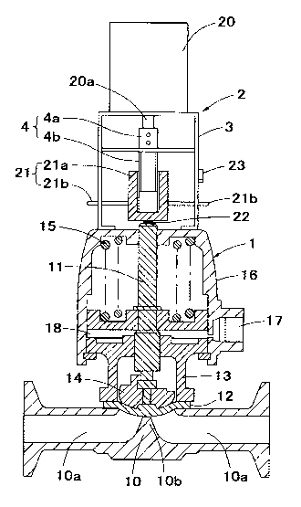
The pneumatically-operating valve (1) has a known
structure comprising a valve assembly and a pneumatic
actuator. The valve assembly includes a valve body (10 ),
stem (11) , valve disc (12), bonnet (13) and compressor
(14). The pneumatic actuator includes a spring (15)
and cap (16) provided on the upper part of the valve
assembly. A fluid channel (l0a) and valve seat (10b)
are provided on the valve body (10). The cap (16) is
provided with an inlet port (17) and an air passageway
(18) through which the air (compressed air) is supplied
from the inlet port (17) to the bottom of the spring
(15).
In the pneumatically-operating valve (1)
described above, the spring (15) is compressed by the
air pressure introduced into the air passageway (18)
when the air is supplied into the cap (16) from the
inlet port (17). Then, the stem (11) and compressor
6
CA 02632282 2008-06-04
Cnglisli Traiislation for PCT Publication
(14) which have been compressed downward by the spring
(15) move upward to separate the valve disc (12) from
the valve seat (10b) . Therefore the fluid channel (10a)
is opened.
On the other hand, when the air supplying from
the inlet port (17) is stopped, the air pressure
introduced into the air passageway (18) decreases, and
the spring (15) is extended. Then the stem (11) and
compressor (14) move downward to contact the valve disc
(12) with the valve seat (lOb). Therefore the fluid
channel (l0a) is closed.
Supplying and stopping air to the pneumatic
actuator is switched by an electromagnetic valve
(shown in Fig. 3).
Fig. 3 is a block diagram showing the whole water
hammerless valve according to the present invention.
Fig. 4 is an enlarged view of a limiting mechanism (2)
extracted from Fig. 1. Fig. 4 (a) shows a front view
and Fig.4 (b) shows a side view.
The limiting mechanism (2) comprises a stepping
motor (20) fixed on the top of the pneumatic actuator,
a vertical movement component (21) provided on a
rotation shaft of the stepping motor ( 20 ), a lower end
detecting component (22) configured to detect arrival
of the vertical moving component (21) at the lower end,
an upper end detecting component (23) configured to
detect the arrival of the vertical movement component
(21) at the upper end, and a control device (24)
configured to control drive of the stepping motor (20)
based on signals from the lower end detecting component
(22), the upper end detecting component (23) and the
above electromagnetic valve.
7
CA 02632282 2008-06-04
English Translation for PCT Publication
The stepping motor (20) is fixed on an upper
portion of base (3) which is placed and fixed on the
surface of the cap (16) of the pneumatic actuator,
wherein the rotation shaft (20a) extends downward and
the rotating shaft and the stem of the valve assembly
are aligned on the same axis.
A male thread member (4) is fixed on the bottom
portion of the rotation shaft of the stepping motor
(20) on the same axis of the rotation shaft (20a) . The
male thread member (4) rotates together with the
rotation shaft (20a) of the stepping motor (20).
The upper portion of a male thread member (4) is
an attachment (4a) including a hole to which the bottom
portion of the rotation shaft (20a) is engaged and
fixed. The bottom portion of a male thread member (4)
is a male thread part (4b) where the male screw thread
is arranged in the outer peripheral wall.
The vertical movement component (21) comprises
a cylindrical body with a bottom (21a) where a female
thread is arranged in the inner peripheral wall, and
a rod (21b) which horizontally extends to the right
and left direction from the outer peripheral wall of
the cylindrical body with the bottom (21a) so that the
rod extending to the right direction is as high as the
rod extending to the left direction.
The male thread part (4b) of the male thread
member (4) is screwed from upward with the female
thread part of the cylindrical body with the bottom
(21a) . The tips of the right and left rods (21b) are
projected laterally from slits (31) provided on the
side of the base (3).
The slit (31) provided on the base (3) extends
upward and downward. The width of the slit (31) is
8
CA 02632282 2008-06-04
English Translation for PCT Publication
almost the same as a diameter of the rod (31) . Thus,
it enables the rod (21b) only to move vertically along
with the slit (31), and enables the cylindrical body
with a bottom (21a) integrated with the rod (21b) only
to move vertically. Therefore, their rotation is not
allowed.
According to the above configuration, when the
rotation shaft (20a) of the stepping motor (20) rotates
in one direction, it also rotates the male thread
member (4) together. As a result, the cylindrical body
with the bottom (21a) screws with the male thread
member (4) to move the rod (21b) upward together. On
the other hand, when the rotation shaft (20a) of the
stepping motor (20) rotates in the opposite direction,
it also reversely rotates the male thread member (4)
together. With their rotation, the cylindrical body
with the bottom (21a) screwed with the male thread
member (4) to move the rod (21b) downward together.
The lower end detecting component (22) comprises
a contact sensor mounted on the lower end of the
vertical movement component (21) . The lower end
detecting component (22) detects contact of the lower
end of the vertical movement component (21) with the
upper end of the stem (see Fig. 1) , and then transmits
the sensing signal to the control system (24).
The upper end detecting component (23) comprises
a limit switch mounted on the upper slit (31) on the
side of the base ( 3). The upper end detecting component
(23) detects the vertical movement component (21) when
it moves upward and the rod (21b) contacts the limit
switch, and then transmits the sensing signal to the
control system (24).
The determined height of the lower end of the
9
CA 02632282 2008-06-04
English Translation for PCT Publication
vertical movement component (21) (the upper limit
height) is higher than the highest position of the
upper end of the stem (11) . Thus, the vertical movement
component (21) moves upward to the position where the
lower end detecting component (22) does not reach the
upper end of the stem when the stem (11) is in the
highest position (the fluid channel is completely
opened).
The control system (24) transmits a control
signal to stop the stepping motor (20) when it received
the detecting signal from the lower end detecting
component (22) and the detecting signal from the upper
end detecting component (23).
Thus, the rotation of the rotation shaft (20a)
of the stepping motor (20) is stopped, and the vertical
movement of the vertical movement component (21) is
also stopped.
Furthermore, the control system (24) controls
drive the stepping motor (20) based on a signal from
the electromagnetic valve (5) . Specifically, when the
electromagnetic valve (5) is turned on to start air
supply to the pneumatic actuator, the control system
(24) receives the "on" signal and transmits the control
signal to rotate the rotation shaft (20a) of the
stepping motor (20) in one direction. Also, when the
electromagnetic valve (5) is turned off to stop
supplying with air to the pneumatic actuator, the
control system (24) receives the "off" signal and
transmits the control signal to rotate the rotation
shaft (20a) of the stepping motor (20) in opposite
direction.
Fig. 5 and 6 are flow charts showing the water
hammerless operation valve according to the present
CA 02632282 2008-06-04
English Translation for PCT Publication
invention.
Initially, the movement of the opened valve will
be described with reference to the Fig. 5.
First, when the electromagnetic valve in the
initial valve-closed position (see Fig. 1) is turned
on, the control signal is transmitted to the stepping
motor (20) from the control system (24) after the
control device (24) receives a signal from the
electromagnetic valve. This enables the rotation shaft
(20a) of the stepping motor (20) to start rotating in
one direction. Thus the lower end of the vertical
movement component (21) starts moving upward apart
from the upper end of the stem.
Start of upward movement is delayed a little bit
from the stepping motor (20) after the air is started
to be supplied to the actuator, and the fluid channel
(l0a) is opened by the valve disc (12) apart from a
valve seat (lOb) as the stem (11) moves upward.
The vertical movement component (21) continues
to move upward while the stem (21) moves upward.
When the upper end detecting component (23)
detects arrival of the vertical movement component
(21) at the upper end, the detecting signal is
transmitted to the control system (24) from the upper
end detecting component (23) . After the control system
(24) receives the detecting signal, the control system
(24) transmits the stop signal to the stepping motor
(20) . Thus, the rotation shaft (20a) of the stepping
motor (20) stops rotating, and the vertical movement
component (21) also stops moving upward.
After that, the stem (11) stops moving upward when
the opening of the fluid channel (10a) is completed,
and opening operation of the valve is terminated. In
11
CA 02632282 2008-06-04
English Translation for PCT Publication
this state, the lower end of the vertical movement
component (21) is apart from the upper end of the stem
(11) (see Fig. 2).
Next, the valve operation in the closed position
will be described with reference to Fig. 6.
When the electromagnetic valve in the initial
valve-opened position (see Fig. 2) is turned off, air
supply to the actuator is stopped, and the stem (11)
starts moving downward.
Next, the control signal is transmitted from the
control system (24) to the stepping motor (20) after
the control system (24) receives the signal from the
electromagnetic valve, and the rotation shaft (20a)
of the stepping motor (20) starts rotating in the
opposite direction. Thus, the lower end of the vertical
movement component (21) moves downward to be apart from
the upper end of the stem.
The stem (21) continues moving downward, and the
valve disc (12) contacts the valve seat (10b) to close
the fluid channel (10a) (see Fig. 1).
The vertical movement component (21) moves
downward after the stem (21) moves downward. When the
lower end of the detecting component (22) detects the
arrival of the lower end of the vertical movement
component (21) at the upper end of the stem, the
detecting signal is transmitted from the lower end
detecting component (22) to the control system (24).
The control system (24) transmits the stop signal to
the stepping motor after the control system (24)
receives the detecting signal. Thus, the rotation
shaft (20a) of the stepping motor (20) stops rotating,
and the vertical movement component (21) is also
stopped moving downward.
12
CA 02632282 2008-06-04
English Translation for PCT Publication
In this state, the lower end of the vertical
movement component (21) contacts the upper end of the
stem (11). Therefore, it is possible to prevent the
stem from moving upward and to control the fluid
channel opening when the water hammer occurs.
INDUSTRIAL APPLICABILITY
The technique of the invention may be used to
control the opening of a fluid channel caused by the
occurrence of a water hammer using a
pneumatically-operating valve for opening and closing
the fluid channel with an operation of a pneumatic
actuator.
BRIEF DESCRIPTION OF THE DRAWINGS
Fig. 1 is a schematic view of the whole water
hammerless valve according to the present invention.
The valve is in the closed position.
Fig. 2 is a schematic view of the whole water
hammerless valve according to the present invention.
The valve is in the opened position.
Fig. 3 is a block diagram showing the whole water
hammerless valve according to the present invention.
Fig. 4 is an enlarged view of the limiting
mechanism extracted from Fig. 1; (a) shows a front view,
and (b) shows a side view.
Fig. 5 is a flow chart showing the movement of
the water hammerless valve according to the present
invention when the valve is in the opened position.
Fig. 6 is a flow chart showing the movement of
the water hammerless valve according to the present
invention when the valve is in the closed position.
EXPLANATION OF THE NUMERALS
1 a pneumatically-operating valve
11 stem
13
CA 02632282 2008-06-04
English Translation for PCT Publication
12 valve disc
2 limiting mechanism
20 stepping motor
20a rotation shaft
21 a vertical movement component
22 lower end detecting component
23 upper end detecting component
24 control device
4 male thread
14