Language selection

Search

Patent 2632445 Summary

Third-party information liability

Some of the information on this Web page has been provided by external sources. The Government of Canada is not responsible for the accuracy, reliability or currency of the information supplied by external sources. Users wishing to rely upon this information should consult directly with the source of the information. Content provided by external sources is not subject to official languages, privacy and accessibility requirements.

Claims and Abstract availability

Any discrepancies in the text and image of the Claims and Abstract are due to differing posting times. Text of the Claims and Abstract are posted:

  • At the time the application is open to public inspection;
  • At the time of issue of the patent (grant).
(12) Patent: (11) CA 2632445
(54) English Title: DEVICE FOR THE ASSISTED LOADING OF A STRETCHER
(54) French Title: DISPOSITIF POUR LE CHARGEMENT ASSISTE D'UNE CIVIERE
Status: Granted and Issued
Bibliographic Data
(51) International Patent Classification (IPC):
  • A61G 1/02 (2006.01)
  • A61G 1/06 (2006.01)
(72) Inventors :
  • CARLETTI, ENRICO (Italy)
  • LAPINI, ALESSANDRO (Italy)
(73) Owners :
  • FERNO-WASHINGTON, INC.
(71) Applicants :
  • FERNO-WASHINGTON, INC. (United States of America)
(74) Agent: GOWLING WLG (CANADA) LLP
(74) Associate agent:
(45) Issued: 2014-03-11
(86) PCT Filing Date: 2006-12-15
(87) Open to Public Inspection: 2007-06-21
Examination requested: 2011-10-17
Availability of licence: N/A
Dedicated to the Public: N/A
(25) Language of filing: English

Patent Cooperation Treaty (PCT): Yes
(86) PCT Filing Number: PCT/IB2006/003633
(87) International Publication Number: WO 2007069066
(85) National Entry: 2008-06-05

(30) Application Priority Data:
Application No. Country/Territory Date
BO2005A000770 (Italy) 2005-12-16

Abstracts

English Abstract


A device for the assisted loading of a stretcher (2) provided with a chassis
(3), comprises at least one driving wheel (4) cinematically connected to a
driving member (5) fed by feeding means (6) and controlled by control means
(7) to activate the at least one driving wheel (4) at least during the loading
of the stretcher into the ambulance.


French Abstract

L'invention concerne un dispositif pour le chargement assisté d'une civière (2) dotée d'un châssis (3), comprenant au moins une roue de transmission (4) raccordée de manière cinématique à un élément de transmission (5) alimenté par des moyens d'alimentation (6) et commandée par des moyens de commande (7) pour activer ladite ou lesdites roues de transmission (4) au moins pendant le chargement de la civière dans l'ambulance.

Claims

Note: Claims are shown in the official language in which they were submitted.

7
WHAT IS CLAIMED IS:
1. A device for assisting loading onto a loading ramp of an ambulance a
stretcher provided
with a chassis and front pivoting legs pivotally attached to the chassis, said
pivoting legs having
idle wheels fit for moving the stretcher, said device comprises:
at least one driving wheel fixed in the front lower portion of the chassis, in
front of the front
pivoting legs remote from said idle wheels, in order to engage the loading
ramp of the ambulance
during loading and unloading of the stretcher; said at least one driving wheel
is operably
connected to a driving member which is electrically powered and controlled to
activate the at
least one driving wheel at least during the loading of the stretcher into the
ambulance, and
a transmission axis to which is fixed a pulley which is connected to the
driving member and
further connected to the transmission axis are two lateral wheels, at least
one of which is the
driving wheel, wherein the lateral wheels are each configured to free wheel at
a higher speed
than that provided by the driving member.
2. The device according to claim 1 wherein the at least one driving wheel
is connected to a
shaft of the driving member by one of a chain, a belt, a gear box, and an
angle transmission.
3. The device according to claim 1 wherein the at least one driving wheel
is connected to a
shaft of the driving member by a belt, wherein said belt is engaged in
respective pulleys of the
shaft and of the at least one driving wheel.
4. The device according to claim 1 wherein the driving member comprises an
electrical
motor powered by a battery.
5. The device according to claim 1 wherein the driving member comprises a
direct current
electric motor and is controlled by switches for forward and reverse motor
motions as well as to
stop the motor.
6. The device according to claim 1 wherein the driving member comprises a
direct current
electric motor and is controlled by potentiometers for adjusting speed of
forward and reverse
motor motions.

8
7. The device according to claim 1 wherein the driving member comprises a
reduction gear
connected downstream to an electric motor.
8. The device according to claim 1 wherein the driving member comprises a
clutch
connected downstream to a reduction gear having a shaft connected to a pulley
which drives the
at least one driving wheel.
9. The device according to claim 1 wherein the driving member comprises a
clutch
connected downstream to a reduction gear having a shaft connected to a pulley
which drives the
at least one driving wheel, and wherein the clutch is one of a controlled
electromagnetic clutch, a
manual clutch, an automatic clutch, and a speed change device.
10. The device according to claim 1 wherein the driving member comprises a
clutch
connected downstream to a reduction gear having a shaft connected to a pulley
which drives the
at least one driving wheel, and wherein the clutch comprises a transmission
gear having at least
one transmission condition and a neutral condition.
11. The device according to claim 1 wherein the at least one driving wheel
is configured to
free wheel at a higher speed than that provided by the driving member.
12. The device according to claim 1 wherein the at least one driving wheel
is provided with a
device which provides circumferential friction to prevent slipping of the at
least one driving
wheel on the loading ramp of the ambulance.
13. The device according to claim 1 wherein the driving member is connected
to the front
lower portion of the chassis.
14. The device according to claim 1 wherein driving member is controlled by
controls
positioned at a rear portion of the stretcher.

Description

Note: Descriptions are shown in the official language in which they were submitted.


CA 02632445 2013-10-09
1
DEVICE FOR THE ASSISTED LOADING OF A STRETCHER
TECHNICAL FIELD
The present invention relates to the technical field of the medical devices
used for
transporting patients and it refers to a device for the assisted loading of a
stretcher
particularly suitable to facilitate the insertion and the loading of the
stretcher in an
ambulance or the like.
BACKGROUND ART
There are known ambulance stretchers equipped with pivoting legs folded in a
direction parallel to the stretcher positioned inside of the ambulance and
that, when
coming out from this ambulance, they rotate about 900 disposing themselves
vertically
in order to support the plane of the stretcher.
An end of each leg has a wheel for the movement of the stretcher out of the
ambulance.
When the stretcher is loaded with the patient in the space of the ambulance,
the legs
contact a counterpart of the ambulance and they are refolded.
A drawback of said known stretchers consists in that when loading in the
ambulance,
the operators need to use a considerable effort to provide the necessary
energy for
loading the heavy stretcher with the patient and to refold the legs.
Other drawback consists in that the impact between the legs and the
counterpart of the
ambulance, due to the eventual small run-up made by the operator, can be
violent and
thus irritating, painful and harmful for the patient particularly for the
traumatized
patient.
Document EP0972505A2 discloses a fitting for facilitating the loading of a
stretcher
onto a platform. The fitting includes a pivotable mounting having a trailing
larger
diameter wheel and a leading smaller diameter wheel.
DISCLOSURE OF THE INVENTION
An object of the present invention is to propose a device for the assisted
loading of a

CA 02632445 2008-06-05
WO 2007/069066
PCT/1B2006/003633
2
stretcher, being able to reduce or avoid the effort of the operator when
loading and/or
unloading the stretcher with the patient.
Other object is to propose a device that allows to reduce the impact between
the legs of
the stretcher and the ambulance in order to increase the comfort and the
safety for the
patient.
The above mentioned objects can be obtained in accordance with the content of
the
claims.
BRIEF DESCRIPTION OF THE DRAWINGS
The characteristics of the invention are evidenced in the following with
particular
reference to the attached drawings, in which:
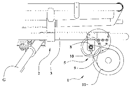
- figure 1 shows a schematic partial side view of the device for the
assisted
loading, associated to a stretcher only partially visible;
- figures 2 and 3 show respectively front view and side view of a
driving member
of figure 1;
- figures 4
and 5 show respectively front view and top view of the device and of
the stretcher of figure 1 in which some parts are removed to better evidence
others parts.
BEST MODE OF CARRYING OUT THE INVENTION
With reference to the figures 1 - 5, numeral 1 indicates the device for the
assisted
loading of a stretcher 2, for example of the type for ambulances, provided
with a chassis
3 and pivoting legs G for the idle wheels fit for moving the stretcher.
The device 1 comprises a pair of lateral driving wheels 4 disposed in the
front lower
portion of the chassis 3, in front of the front pivoting legs G, in order to
engage the
loading ramp of the ambulance during the loading and unloading phases of the
stretcher.

CA 02632445 2008-06-05
WO 2007/069066
PCT/1B2006/003633
3
Said driving wheels 4 are connected to a transmission axis 17 to which is
fixed a pulley
11 of the driving wheels cinematically connected, by means of a timing belt 9,
to a
pulley 10 of an outlet shaft 8 of a driving member 5.
Said driving member 5 is fed by feeding mean 6 by means of control mean 7 to
activate
the driving wheels 4 when loading the stretcher into the ambulance and,
eventually,
when unloading it.
In alternative, the invention provides that the device is provided with a
single driving
wheel 4 and/or that the connection of said wheel to the outlet shaft 8 of the
driving
member 5 is carried out by a chain, a trapezoidal belt, a gear box or angle
transmission
connected by a shaft or similar transmissions.
The driving member 5 is preferably connected to the front lower portion of the
chassis 3
and comprises a motor 12, a reduction gear 13 and a clutch mean 14 cascade
connected.
The motor 12 is electrical type fed by storage means, for example a
rechargeable
battery, of the feeding means 6 and is controlled by the control means 7 of
electrical
type.
More precisely, the motor 12 is direct current type and the control means 7
are switch
type with forward and reverse motion as well as stop of the motor 12, or they
are
potentiometer type for adjusting the speed of the forward and reverse motion
and the
stop.
The clutch mean 14 could comprise an electromagnetic clutch controlled by the
control
means 7.
Optionally the clutch mean (14) could comprise a manual or electric operated
transmission gear having at lest one transmission condition and a neutral
condition.

CA 02632445 2008-06-05
WO 2007/069066
PCT/1B2006/003633
4
The outlet shaft 8 of the clutch mean 14 is connected to the pulley 10 and,
preferably, is
disposed transversally in respect to the stretcher, parallel in respect to the
shafts of
motor and of the reduction gear.
In alternative the invention provides the adoption, in stead of the motor with
the
reduction gear, of a motor of the type having high torque even at very low
revolutions
speed and it provides that the clutch mean 14 can consist of, or can comprise,
a manual
or an automatic clutch or a speed change device.
The driving wheels 4 can comprise respective free wheel means 15, for example
of so-
called "ratchet and pawl" type, connecting to the transmission axis 17 to
allow the
operator to effect the loading of the stretcher into the ambulance, after the
initial ramp
tract, pushing it at a higher speed than the speed of the device.
The driving wheels 4 are provided with circumferential friction means 16, for
example
consisting of a rubber ring, fit to prevent the slipping on the ramp of the
ambulance.
In alternative the invention provides the adoption of a small caterpillar
tract, which is
note and not shown, for example made of reinforced rubber or metal made with
rubber
inserts, each being engaged and tensioned between an idle wheel and a driving
wheel 4.
The control means 7 are positioned in the rear portion of the stretcher for an
easy
operation by the operator.
The feeding means 6 and the connecting wirings C of these latter with the
control means
7 and with the driving member 5 are fixed to the chassis 3.
Optionally the device could comprise at least first sensor means and second
sensor
means respectively fit for detecting a condition of stop in a vertical
operating position of
the front legs G of the stretcher 2 and a position of the stretcher 2 close to
the external
edge of the loading ramp in the exiting condition of the stretcher 2.

CA 02632445 2008-06-05
WO 2007/069066
PCT/1B2006/003633
Said sensor means first and second are linked to the control means 7 to stop
the driving
member 5 and the at least one driving wheel 4 when the stretcher 2 is exiting
out of the
ambulance and at least one of the front legs G is not stopped in vertical
operating
position.
5
Such safety provision avoid the risk that the stretcher can come out from the
ambulance
without the correct positioning and blocking of the legs so rendering almost
impossible
the falling of the front portion of the stretcher.
The first sensor means comprises at least two switches or detectors, for
instance of
magnetic type, each connected to a safety lock of a respective front leg G.
The second sensor means comprises at least two switches or detectors, for
instance of
magnetic type, fixed to the ambulance, fit to match, one after an other, a
matching
mean, for instance e protrusion, of the stretcher 2 to detect the exiting
condition of the
stretcher 2 and the positioning of the front portion of the stretcher 2 close
to the edge of
the loading ramp.
The operation of the device provides, for example, that the operator pushes
the stretcher
with the patient until to the matching of the driving wheels 4 with the short
ramp of the
ambulance provided for the loading wheels of the normal stretchers and that,
by means
of the control means 7, he activates driving member 5 provoking to the
controlled
rotation of the drive wheels and the entrance of the stretcher into the
ambulance.
It's important to observe that, advantageously, the device does not require
any
modification of the ambulances and it can be easily applied also to the
stretchers
existing before of the known type.
An advantage of the present invention is to provide a device for the assisted
loading of a
stretcher which can let the operator to reduce or to avoid the effort when
loading and/or
unloading the stretcher with the patient.

CA 02632445 2008-06-05
WO 2007/069066
PCT/1B2006/003633
6
Other advantage is to provide a device which can reduce the impact between the
legs of
the stretcher and the ambulance in order to increase the comfort and the
safety for the
patient.

Representative Drawing
A single figure which represents the drawing illustrating the invention.
Administrative Status

2024-08-01:As part of the Next Generation Patents (NGP) transition, the Canadian Patents Database (CPD) now contains a more detailed Event History, which replicates the Event Log of our new back-office solution.

Please note that "Inactive:" events refers to events no longer in use in our new back-office solution.

For a clearer understanding of the status of the application/patent presented on this page, the site Disclaimer , as well as the definitions for Patent , Event History , Maintenance Fee  and Payment History  should be consulted.

Event History

Description Date
Common Representative Appointed 2019-10-30
Change of Address or Method of Correspondence Request Received 2018-01-10
Grant by Issuance 2014-03-11
Inactive: Cover page published 2014-03-10
Inactive: Final fee received 2013-12-23
Pre-grant 2013-12-23
Notice of Allowance is Issued 2013-11-07
Letter Sent 2013-11-07
Notice of Allowance is Issued 2013-11-07
Inactive: Approved for allowance (AFA) 2013-11-05
Inactive: Q2 passed 2013-11-05
Amendment Received - Voluntary Amendment 2013-10-09
Inactive: S.30(2) Rules - Examiner requisition 2013-04-11
Letter Sent 2011-10-24
Request for Examination Requirements Determined Compliant 2011-10-17
All Requirements for Examination Determined Compliant 2011-10-17
Request for Examination Received 2011-10-17
Inactive: Cover page published 2008-09-26
Inactive: Notice - National entry - No RFE 2008-09-24
Inactive: First IPC assigned 2008-07-03
Application Received - PCT 2008-07-02
Inactive: Declaration of entitlement - PCT 2008-06-26
National Entry Requirements Determined Compliant 2008-06-05
Application Published (Open to Public Inspection) 2007-06-21

Abandonment History

There is no abandonment history.

Maintenance Fee

The last payment was received on 2013-11-19

Note : If the full payment has not been received on or before the date indicated, a further fee may be required which may be one of the following

  • the reinstatement fee;
  • the late payment fee; or
  • additional fee to reverse deemed expiry.

Please refer to the CIPO Patent Fees web page to see all current fee amounts.

Owners on Record

Note: Records showing the ownership history in alphabetical order.

Current Owners on Record
FERNO-WASHINGTON, INC.
Past Owners on Record
ALESSANDRO LAPINI
ENRICO CARLETTI
Past Owners that do not appear in the "Owners on Record" listing will appear in other documentation within the application.
Documents

To view selected files, please enter reCAPTCHA code :


To view images, click a link in the Document Description column. To download the documents, select one or more checkboxes in the first column and then click the "Download Selected in PDF format (Zip Archive)" or the "Download Selected as Single PDF" button.

List of published and non-published patent-specific documents on the CPD .

If you have any difficulty accessing content, you can call the Client Service Centre at 1-866-997-1936 or send them an e-mail at CIPO Client Service Centre.


Document
Description 
Date
(yyyy-mm-dd) 
Number of pages   Size of Image (KB) 
Description 2008-06-05 6 228
Drawings 2008-06-05 4 68
Claims 2008-06-05 3 139
Abstract 2008-06-05 1 62
Representative drawing 2008-09-25 1 11
Cover Page 2008-09-26 1 38
Description 2013-10-09 6 230
Claims 2013-10-09 2 85
Drawings 2013-10-09 4 64
Cover Page 2014-02-06 1 40
Reminder of maintenance fee due 2008-09-24 1 111
Notice of National Entry 2008-09-24 1 193
Reminder - Request for Examination 2011-08-16 1 122
Acknowledgement of Request for Examination 2011-10-24 1 176
Commissioner's Notice - Application Found Allowable 2013-11-07 1 162
PCT 2008-06-06 6 233
PCT 2008-06-05 5 191
Correspondence 2008-06-26 2 63
PCT 2006-12-15 1 42
Correspondence 2013-12-23 2 48