Language selection

Search

Patent 2632624 Summary

Third-party information liability

Some of the information on this Web page has been provided by external sources. The Government of Canada is not responsible for the accuracy, reliability or currency of the information supplied by external sources. Users wishing to rely upon this information should consult directly with the source of the information. Content provided by external sources is not subject to official languages, privacy and accessibility requirements.

Claims and Abstract availability

Any discrepancies in the text and image of the Claims and Abstract are due to differing posting times. Text of the Claims and Abstract are posted:

  • At the time the application is open to public inspection;
  • At the time of issue of the patent (grant).
(12) Patent: (11) CA 2632624
(54) English Title: AIRCRAFT AIR CONDITIONING SYSTEM WITH CYCLONE DISCHARGERS
(54) French Title: SYSTEME DE CONDITIONNEMENT D'AIR POUR AERONEF DOTE DE DISPOSITIFS DE REFOULEMENT CYCLONIQUES
Status: Expired and beyond the Period of Reversal
Bibliographic Data
(51) International Patent Classification (IPC):
  • B64D 13/00 (2006.01)
  • F24F 13/04 (2006.01)
(72) Inventors :
  • HUBER, ALFRED (Germany)
  • KOGUT, JACEK (Germany)
  • TREIMER, THOMAS (Germany)
  • BABAK, SLAWA (Germany)
(73) Owners :
  • AIRBUS OPERATIONS GMBH
(71) Applicants :
  • AIRBUS OPERATIONS GMBH (Germany)
(74) Agent: OYEN WIGGS GREEN & MUTALA LLP
(74) Associate agent:
(45) Issued: 2011-08-09
(86) PCT Filing Date: 2007-02-06
(87) Open to Public Inspection: 2007-08-16
Examination requested: 2008-06-06
Availability of licence: N/A
Dedicated to the Public: N/A
(25) Language of filing: English

Patent Cooperation Treaty (PCT): Yes
(86) PCT Filing Number: PCT/EP2007/000998
(87) International Publication Number: EP2007000998
(85) National Entry: 2008-06-06

(30) Application Priority Data:
Application No. Country/Territory Date
10 2006 005 543.8 (Germany) 2006-02-07

Abstracts

English Abstract


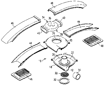
The invention relates to an aircraft air conditioning system with at least one
fresh air supply line (14) for conveying
fresh air into an aircraft cabin, wherein the fresh air is blown out into the
aircraft cabin via at least one discharger (48). In order to
form the system so as to save weight and costs, a cyclone unit (10) is
disposed in the vicinity of the discharger (48), the unit having
an inlet opening (12), which communicates with the fresh air supply line (14),
an intake opening (28), through which air is sucked
in from the aircraft cabin, and at least one outlet opening (24), which
communicates with the at least one discharger (48), wherein
a cyclone flow is produced in the cyclone unit (10) during operation of the
aircraft air conditioning system by means of the fresh
air serving as incoming air and further wherein air is sucked in through the
intake opening (28) from the aircraft cabin and expelled
together with the fresh air through the outlet opening (24).


French Abstract

L'invention concerne un système de conditionnement d'air pour aéronef, comprenant au moins une conduite d'amenée d'air frais (14) servant à introduire de l'air frais dans une cabine d'aéronef, l'air frais étant chassé dans la cabine d'aéronef par au moins un dispositif de refoulement (48). Dans le but de réduire le poids et les coûts de fabrication du système, une unité à cyclone (10) est disposée au voisinage dudit au moins un dispositif de refoulement (48), ladite unité à cyclone comprenant une ouverture d'entrée (12) qui communique avec la conduite d'amenée d'air frais (14), une ouverture d'admission (28) par laquelle l'air est aspiré de la cabine d'aéronef, et au moins une ouverture de sortie (24) qui communique avec ledit au moins un dispositif de refoulement (48). Un écoulement cyclonique est généré dans l'unité à cyclone (10) pendant le fonctionnement du système de conditionnement d'air pour aéronef grâce à l'air frais servant d'air d'entrée, et de l'air est aspiré de la cabine d'aéronef par l'ouverture d'admission (28) et expulsé avec l'air frais par l'ouverture de sortie (24).

Claims

Note: Claims are shown in the official language in which they were submitted.


-6-
Claims
1. Aircraft air conditioning system, with at least one fresh air supply line
(14) for
conveying fresh air into an aircraft cabin, wherein the fresh air is blown out
into the
aircraft cabin via at least one discharger (48), characterised in that a
cyclone unit
(10) is disposed in the vicinity of the discharger (48), the unit having a
main body
(16), a distributor element (34), an inlet opening (12), which communicates
with the
fresh air supply line (14), an intake opening (28), through which air is
sucked in from
the aircraft cabin, and at least one outlet opening (24), which communicates
with the
at least one discharger (48), wherein a first cyclone flow is produced in the
main
body (16) of the cyclone unit (10) during operation of the aircraft air
conditioning
system only by means of the fresh air from the fresh air supply line (14) and
a
second cyclone flow is produced in the distributor element (34) by means of
the
fresh air of the first cyclone flow serving as incoming air and the cabin air,
and
further wherein the cabin air is sucked in through the intake opening (28)
from the
aircraft cabin and expelled together with the fresh air through the outlet
opening
(24).
2. Aircraft air conditioning system according to Claim 1, characterised in
that the
intake opening (28) communicates with the aircraft cabin via an intake duct.
3. Aircraft air conditioning system according to Claim 1, characterised in
that the
intake opening (28) communicates directly with the aircraft cabin.
4. Aircraft air conditioning system according to any one of Claims 1 to 3,
characterised in that a main body (16) of the cyclone unit (10) is of
horizontally split
construction, having an upper part (20), which defines the outlet opening (24)
in its
upper region, and a lower part (18), which, together with the upper part (20),
defines a toroidal hollow space (22) whose radially inner wall is formed by a
hollow
truncated cone (26) extending from the lower part (18) upwards into the region
of
the outlet opening (24).
5. Aircraft air conditioning system according to Claim 4, characterised in
that the
maximum cross section of the hollow truncated cone (26) forms the intake
opening
(28).

-7-
6. Aircraft air conditioning system according to any one of Claims 1 to 5,
characterised in that the outlet opening (24) communicates with two or more
dischargers (48).
7. Aircraft air conditioning system according to any one of Claims 1 to 6,
characterised in that each discharger (48) communicates with the outlet
opening
(24) through a exhaust line (42).
8. Aircraft air conditioning system according to Claim 7, characterised in
that each
exhaust line (42) opens out by way of its end which is opposite the discharger
(48) in
a distributor element (34) which communicates directly with the outlet opening
(24).
9. Aircraft air conditioning system according to Claim 8, characterised in
that the
distributor element (34) comprises a toroidal body (36) with a central opening
(38)
which establishes the communication with the outlet opening (24), and that the
exhaust lines (42) extend radially outwards from the toroidal body (36).
10. Aircraft air conditioning system according to Claim 9, characterised in
that each
exhaust line (42) is of horizontally split formation.
11. Aircraft air conditioning system according to any one of Claims 1 to 10,
characterised in that the cyclone unit (10) at the same time serves as a
separator for
particles contained in the air.

Description

Note: Descriptions are shown in the official language in which they were submitted.


CA 02632624 2008-06-06
WO 2007/090608 PCT/EP2007/000998
-1-
Aircraft air conditioning system with cyclone dischargers
The present invention relates to an aircraft air conditioning system with at
least one
fresh air supply line for conveying fresh air into an aircraft cabin, wherein
the fresh
air is blown out into the aircraft cabin via at least one discharger. In this
respect
"fresh air" means air which has not yet been in the aircraft cabin. The fresh
air
usually comes from a so-called AGU (air generation unit), i.e. an air
treatment
system which, using engine bleed air, provides suitably conditioned fresh air
which
can be routed into the aircraft cabin. In the present case the term "aircraft
cabin" is
understood to be the interior of an aircraft cabin. This may be the pilot's
cockpit, the
passenger compartment and/or the cargo compartment.
i5 In order to reduce the amount of fresh air required for the aircraft cabin,
it is known
to recirculate a certain proportion of the air which is contained in the
aircraft cabin,
i.e. to withdraw this proportion from the aircraft cabin, to treat it and then
to return it
to the aircraft cabin, usually together with the fresh air which is in any
case
continuously supplied to the aircraft cabin. For this purpose the recirculated
air must
be mixed with the fresh air, which usually takes place at a central location,
for
example in a mixer connected downstream of the central air treatment unit
(AGU).
This obviously requires long line paths, which not only increase the
production costs
of an aircraft, but also take up installation space and have weight-increasing
consequences.
The object of the invention is therefore to provide an improved aircraft air
conditioning system which eliminates the above-mentioned problems.
Starting out from a generally known aircraft air conditioning system as
initially
mentioned, this object is achieved according to the invention in that a
cyclone unit is
disposed in the vicinity of the discharger, wherein the unit has an -inlet
opening,
which communicates with the fresh air supply line, an intake opening, through
which
air is sucked in from the aircraft cabin, and at least one outlet opening,
which
communicates with the at least one discharger, wherein a cyclone flow is
produced in
the cyclone unit during operation of the aircraft air conditioning system by
means of
the fresh air serving as incoming air and further wherein air is sucked in
through the
intake opening from the aircraft cabin and expelled together with the fresh
air

CA 02632624 2008-06-06
WO 2007/090608 PCT/EP2007/000998
-2-
through the outlet opening. The system according to the invention therefore
needs
long lines merely for the fresh air which is to be supplied, while the air
which is taken
from the aircraft cabin and is to be recirculated is mixed with the fresh air
and can
optionally also be cleaned locally in the cyclone unit. The system according
to the
invention therefore saves weight and requires little production and assembly
expenditure. Moreover, it has a form which is optimised in flow terms.
Here the words "in the vicinity of the discharger" mean that the cyclone unit
does not
represent a central mixing unit which is responsible for a plurality of
dischargers, but
that a cyclone unit is associated with each discharger or a few dischargers
together,
the intake opening of which unit communicates with the aircraft cabin either
directly
or via a short intake duct. In the simplest case the discharger is a component
which
defines an outflow opening. In a further developed form the discharger may
have
one or more guide vanes which span the outflow opening in order to distribute
the
outflowing air in a more uniform manner and/or to direct it in a certain
direction.
According to a preferred embodiment, a main body of the cyclone unit is of
horizontally split construction and comprises an upper part, which in its
central region
defines the outlet opening, and a lower part, which, together with the upper
part,
defines a toroidal hollow space whose radially inner wall is formed by a
hollow
truncated cone extending from the lower part upwards into the region of the
outlet
opening. A cyclone flow is produced in the toroidal hollow space by
introducing the
incoming air tangentially. An embodiment of this kind is inexpensive to
manufacture
and easy to assemble.
The maximum cross section of the hollow truncated cone preferably forms the
intake
opening in the above-mentioned embodiment. As stated, the intake opening may
either suck in air directly from the aircraft cabin, for example in the cargo
compartment of an aircraft, in which the cyclone unit can be disposed without
being
concealed, or it may communicate with a short intake duct via which the air is
sucked
in from, for example, a passenger compartment of a commercial aircraft. In the
latter
case the cyclone unit is preferably fitted in a concealed manner, for example
behind
covering panels of the aircraft cabin. If the intake opening communicates
directly
with the aircraft cabin, a protective grille preferably spans the intake
opening cross
section in order to prevent undesirable parts from penetrating into the
cyclone unit.

CA 02632624 2008-06-06
WO 2007/090608 PCT/EP2007/000998
-3-
As already mentioned, the outlet opening of the cyclone unit may also
communicate
with two or more dischargers instead of with one. Particularly when the outlet
opening communicates with more than one discharger, each discharger
communicates with the outlet opening through an exhaust line. When compared
with
the lines required in an air conditioning system having a central mixing unit,
these
exhaust lines are also very short, and their length may correspond
approximately to
the length of the intake duct, if such an intake duct is provided.
In an embodiment in which each discharger communicates with the outlet opening
of
the cyclone unit through a exhaust line, each exhaust line preferably opens
out by
way of its end which is opposite the discharger in a distributor element which
communicates directly with the outlet opening of the cyclone unit. A plurality
of
dischargers can in this way be supplied in a space-saving manner by means of
one
and the same cyclone unit. According to a preferred configuration, the
distributor
element comprises a toroidal body with a central opening which establishes the
communication with the outlet opening of the cyclone unit, and the exhaust
lines
extend radially outwards from the toroidal body. The cyclone flow which is
initially
produced in the cyclone unit is maintained in a distributor element of this
kind, so
that the fresh air which is mixed with the recirculated air can be uniformly
distributed
to the individual dischargers. In a structurally advantageous manner, each
exhaust
line is preferably of horizontally split formation, and can therefore be
easily
implemented, e.g. as an injection-moulded part, and easily assembled.
If desired, the cyclone unit may at the same time serve as a separator for
particles
contained in the air without a high additional structural expenditure.
An embodiment of a cyclone unit according to the invention for an aircraft air
conditioning system is illustrated in detail in the following on the basis of
the
accompanying, schematic figures, in which:
Figure 1 shows a cyclone unit of an aircraft air conditioning system according
to
the invention in a three-dimensional and exploded representation,
Figure 2 is a three-dimensional representation, broken open transversely, of
the
cyclone unit from Figure 1, and

CA 02632624 2008-06-06
WO 2007/090608 PCT/EP2007/000998
-4-
Figure 3 is another three-dimensional representation, broken open
longitudinally,
of the cyclone unit from Figure 1.
Figure 1 shows in a three-dimensional exploded representation a cyclone unit
10, the
s inlet opening 12 of which communicates with a fresh air supply line 14 of an
aircraft
air conditioning system. The supply line 14 conveys fresh air, which usually
comes
from a central air treatment unit (AGU = air generation unit) of the aircraft,
to the
cyclone unit 10.
The cyclone unit 10 has a main body 16 (see Figure 2) consisting of a lower
part 18
and an upper part 20 (see Figure 1) which together define a toroidal hollow
space 22
in the interior of the main body 16. The upper part 20 has a central open
region
which forms an outlet opening 24 of the cyclone unit 10. A radially inner wall
of the
toroidal hollow space 22 is formed by a hollow truncated cone 26 which extends
upwards from the bottom of the lower part 18 and ends approximately in the
region
of the outlet opening 24 (see in particular Figure 2). In the represented
embodiment,
the hollow truncated cone 26 is formed integrally with the lower part 18.
The maximum cross section, located in the region of the bottom of the lower
part 18,
of the hollow truncated cone 26 forms an intake opening 28 of the cyclone unit
10
which, for safety reasons, is spanned by a protective grille 30 which is
fastened to a
ring 32 at the lower part 18 (see Figures 1 and 3).
A distributor element 34 communicates directly with the outlet opening 24 of
the
cyclone unit 10, which element, in the represented example, is of integral
construction and comprises a toroidal body 36 with a lower central opening 38
which
faces the outlet opening 24 and communicates with the latter in the assembled
state.
Through the outlet opening 24 of the cyclone unit 10 and the lower opening 38
of
the distributor element 34 the toroidal hollow space 22 is in fluid
communication with
an additional toroidal hollow space 37 formed in the interior of the toroidal
body 36
(see Figures 2 and 3). Extending from the distributor element 34 in the
illustrated
embodiment, more specifically from the toroidal body 36 thereof, are two
flanges 40
arranged opposite to each other, which tap the additional toroidal hollow
space 37 in
the distributor element 34 and serve to fit a respective exhaust line 42,
which lines
extend substantially radially outwards from the toroidal body 36. An
indentation 43
(see Figure 3) is formed in a central region of the upper top face of the
distributor

CA 02632624 2008-06-06
WO 2007/090608 PCT/EP2007/000998
-5-
element 34, which indentation extends into the distributor element 34 in the
direction of the free end of the hollow truncated cone 26 of the cyclone unit
10.
Each exhaust line 42 is split horizontally and therefore consists of a lower
exhaust
line part 44 and an upper exhaust line part 46 (see Figure 1). A discharger 48
is
disposed at the free end of each exhaust line 42, being formed in the
illustrated
embodiment by a blow-out grille which is built into the opening formed at the
free
end of the exhaust line 42.
The operation of the cyclone unit 10 shall now be illustrated. Fresh air is
supplied as
incoming air to the cyclone unit 10 through the supply line 14. This incoming
air
flows through the inlet opening 12 tangentially into the toroidal hollow space
22 of
the cyclone unit 10 and develops in the latter a cyclone-like flow. The
cyclone flow
generates in its radially inner centre, also called eye, a negative pressure
which
causes cabin air to be sucked into the cyclone unit 10 through the intake
opening 28
and the hollow truncated cone 26. After the cabin air which has been sucked in
has
flowed through the free end of the hollow truncated cone 26, it strikes a face
50,
plane in this case, which is formed by the central indentation 43 of the
distributor
element 34 and radially outwardly deflects the air which is sucked in and is
to be
recirculated.
The fresh air circulating in the toroidal hollow space 22 moves, while
continuously
circulating, through the outlet opening 24 of the cyclone unit 10 and the
opening 38
of the distributor element upwards into the distributor element 34, where it
meets
the cabin air which is deflected by the face 50 and which has flowed through
the
intake opening 28 into the cyclone unit 10. The two air masses, fresh air and
sucked-
in cabin air, now circulate together in the additional toroidal hollow space
37, which
is formed by the toroidal body 36 of the distributor element 34, and in the
process
mix intimately. There is accordingly also a cyclone flow in the additional
toroidal
hollow space 37.
The air which is mixed in this way leaves the distributor element 34 in the
radial
direction through the flanges 40 and flows through the exhaust lines 42 to the
dischargers 48 and through these into the aircraft cabin.
All the components of the arrangement described above can be constructed
inexpensively as plastics injection-moulded parts.

Representative Drawing
A single figure which represents the drawing illustrating the invention.
Administrative Status

2024-08-01:As part of the Next Generation Patents (NGP) transition, the Canadian Patents Database (CPD) now contains a more detailed Event History, which replicates the Event Log of our new back-office solution.

Please note that "Inactive:" events refers to events no longer in use in our new back-office solution.

For a clearer understanding of the status of the application/patent presented on this page, the site Disclaimer , as well as the definitions for Patent , Event History , Maintenance Fee  and Payment History  should be consulted.

Event History

Description Date
Time Limit for Reversal Expired 2019-02-06
Letter Sent 2018-02-06
Inactive: Office letter 2012-04-03
Inactive: Reversal of will be deemed expired status 2012-03-29
Letter Sent 2012-02-06
Letter Sent 2011-08-18
Grant by Issuance 2011-08-09
Inactive: Cover page published 2011-08-08
Pre-grant 2011-05-25
Inactive: Final fee received 2011-05-25
Notice of Allowance is Issued 2011-04-04
Letter Sent 2011-04-04
Notice of Allowance is Issued 2011-04-04
Inactive: Approved for allowance (AFA) 2011-03-31
Amendment Received - Voluntary Amendment 2010-05-31
Inactive: S.30(2) Rules - Examiner requisition 2010-03-12
Letter Sent 2009-01-30
Inactive: Correspondence - PCT 2008-11-25
Inactive: Single transfer 2008-11-25
Inactive: Declaration of entitlement/transfer - PCT 2008-10-01
Inactive: Cover page published 2008-10-01
Letter Sent 2008-09-29
Inactive: Acknowledgment of national entry - RFE 2008-09-29
Inactive: First IPC assigned 2008-07-04
Application Received - PCT 2008-07-03
National Entry Requirements Determined Compliant 2008-06-06
Request for Examination Requirements Determined Compliant 2008-06-06
All Requirements for Examination Determined Compliant 2008-06-06
Application Published (Open to Public Inspection) 2007-08-16

Abandonment History

There is no abandonment history.

Maintenance Fee

The last payment was received on 2011-01-19

Note : If the full payment has not been received on or before the date indicated, a further fee may be required which may be one of the following

  • the reinstatement fee;
  • the late payment fee; or
  • additional fee to reverse deemed expiry.

Patent fees are adjusted on the 1st of January every year. The amounts above are the current amounts if received by December 31 of the current year.
Please refer to the CIPO Patent Fees web page to see all current fee amounts.

Owners on Record

Note: Records showing the ownership history in alphabetical order.

Current Owners on Record
AIRBUS OPERATIONS GMBH
Past Owners on Record
ALFRED HUBER
JACEK KOGUT
SLAWA BABAK
THOMAS TREIMER
Past Owners that do not appear in the "Owners on Record" listing will appear in other documentation within the application.
Documents

To view selected files, please enter reCAPTCHA code :


To view images, click a link in the Document Description column. To download the documents, select one or more checkboxes in the first column and then click the "Download Selected in PDF format (Zip Archive)" or the "Download Selected as Single PDF" button.

List of published and non-published patent-specific documents on the CPD .

If you have any difficulty accessing content, you can call the Client Service Centre at 1-866-997-1936 or send them an e-mail at CIPO Client Service Centre.


Document
Description 
Date
(yyyy-mm-dd) 
Number of pages   Size of Image (KB) 
Description 2008-06-05 5 291
Drawings 2008-06-05 3 64
Claims 2008-06-05 2 78
Abstract 2008-06-05 2 80
Representative drawing 2008-09-29 1 20
Claims 2008-06-06 2 81
Claims 2010-05-30 2 73
Acknowledgement of Request for Examination 2008-09-28 1 175
Notice of National Entry 2008-09-28 1 202
Courtesy - Certificate of registration (related document(s)) 2009-01-29 1 104
Commissioner's Notice - Application Found Allowable 2011-04-03 1 163
Maintenance Fee Notice 2018-03-19 1 180
PCT 2008-06-05 3 102
Correspondence 2008-09-29 1 15
Correspondence 2008-11-24 1 48
Correspondence 2011-05-24 1 34
Correspondence 2012-04-02 1 16