Language selection

Search

Patent 2632863 Summary

Third-party information liability

Some of the information on this Web page has been provided by external sources. The Government of Canada is not responsible for the accuracy, reliability or currency of the information supplied by external sources. Users wishing to rely upon this information should consult directly with the source of the information. Content provided by external sources is not subject to official languages, privacy and accessibility requirements.

Claims and Abstract availability

Any discrepancies in the text and image of the Claims and Abstract are due to differing posting times. Text of the Claims and Abstract are posted:

  • At the time the application is open to public inspection;
  • At the time of issue of the patent (grant).
(12) Patent Application: (11) CA 2632863
(54) English Title: FLOOR COVERINGS TO BE PLACED UNDERNEATH DRUMS AND DRUMKITS
(54) French Title: REVETEMENT DE PLANCHER A PLACER EN DESSOUS DE BATTERIES
Status: Deemed Abandoned and Beyond the Period of Reinstatement - Pending Response to Notice of Disregarded Communication
Bibliographic Data
(51) International Patent Classification (IPC):
  • G01D 13/00 (2006.01)
(72) Inventors :
  • BASKERVILLE, IAN (United Kingdom)
(73) Owners :
  • IAN BASKERVILLE
(71) Applicants :
  • IAN BASKERVILLE (United Kingdom)
(74) Agent: BENNETT JONES LLP
(74) Associate agent:
(45) Issued:
(86) PCT Filing Date: 2006-11-30
(87) Open to Public Inspection: 2007-06-07
Availability of licence: N/A
Dedicated to the Public: N/A
(25) Language of filing: English

Patent Cooperation Treaty (PCT): Yes
(86) PCT Filing Number: PCT/GB2006/004464
(87) International Publication Number: GB2006004464
(85) National Entry: 2008-06-02

(30) Application Priority Data:
Application No. Country/Territory Date
0524736.6 (United Kingdom) 2005-12-03

Abstracts

English Abstract


Apparatus is provided for covering a floor in order to place a drum or a
plurality of drums on the floor. The apparatus comprises a flexible substrate
having an upper surface and an under surface for covering a region of a floor
onto which a drum is to be assembled such that a plurality of support feet
contact the upper surface of the substrate and a plurality of rigid foot
locators extending from the upper surface each at a desired location for a
specific one of the support feet. The foot locators are secured firmly to the
substrate without fixtures that protrude from the under surface, so as not to
cause floor damage and the foot locators restrict movement of the support feet
thereby restricting movement of a supported drum while the drum is being
played.


French Abstract

La présente invention concerne un appareil pour recouvrir un plancher afin de placer une batterie ou une pluralité de batteries sur le plancher. L~appareil comprend une couche flexible ayant une surface supérieure et une surface inférieure permettant de recouvrir une zone de plancher sur laquelle une batterie est montée de façon à ce que les multiples pieds de support soient en contact avec la surface supérieure de la couche et que les multiples dispositifs de localisation de pied rigides s~étendent chacun de la surface supérieure à un emplacement désiré spécifique à chaque pied de support. Les dispositifs de localisation de pied sont fixés fermement à la couche sans fixation ressortant par la surface inférieure, de façon à ne pas endommager le plancher et de façon à ce que les dispositifs de localisation de pied limitent le mouvement des pieds de support, limitant ainsi les mouvements de la batterie ainsi supportée lorsqu~on l'utilise.

Claims

Note: Claims are shown in the official language in which they were submitted.

7
Claims
1. Apparatus for covering a floor in order to place a drum or a
plurality of drums (a drum kit) on said floor, said apparatus comprising:
a flexible substrate having an upper surface and an under surface for
covering a region of a floor onto which a drum is to be assembled such that a
plurality of support feet contact the upper surface of said substrate;
a plurality of rigid foot locators extending from said upper surface, each
at a desired location for a specific one of said support feet, wherein
said foot locators are secured firmly to the substrate without fixtures that
protrude from said under surface so as not to cause floor damage; and
the foot locators restrict movement of the support feet, thereby
restricting movement of a supported drum while said drum is being played.
2. Apparatus according to claim 1, wherein said substrate is a
fabric material.
3. Apparatus according to claim 2, wherein said substrate is a
carpet.
4. Apparatus according to any of claims 1 to 3, wherein said under
surface is resistant to sliding over a floor, without marking or damaging said
floor.
5. Apparatus according to any preceding claim, wherein said foot
locators are substantially C-shaped.

8
6. Apparatus according to claim 5, wherein said C-shaped foot
locators are positioned such that a support foot is receivable through the
opening defined by the C-shape and the opposite side of a C-shaped locator
restricts movement of a located support foot while the drums are being played.
7. Apparatus according to any preceding claim, wherein said foot
locators are fabricated from a light-weight metal alloy or a strong plastics
material.
8. Apparatus according to any preceding claim, wherein said foot
locators are colour-coded to facilitate the identification of the correct
desired
locations.
9. Apparatus according to any preceding claim, wherein the foot
locators are firmly secured to the substrate by a connector or plurality of
connectors that each extend through a hole in said substrate.
10. Apparatus according to any preceding claim, wherein the
connector that secures the foot locators comprises a jet nut and a screw.
11. Apparatus according to any preceding claim, wherein, the
connector is pulled into the under surface of the substrate, such that the
connector does not contact with the floor below.
12. A method of assembling a drum kit such that support feet are
positioned at desired locations, comprising the steps of:
laying a flexible substrate on a floor, wherein said substrate has an
upper surface and an under surface, a plurality of rigid foot locators extend
from said upper surface, and said foot locators are secured firmly to said
substrate without fixtures that protrude from said under surface so as not to
cause floor damage;

9
assembling drum supports that have support feet and inserting one or
more of said support feet into a pre-specified one of said foot locators, such
that said foot locators restrict movement of said support feet and thereby
restrict movement of a supported drum while the drum is being played.
13. A method according to claim 12, wherein said insertion of support
feet into a pre-specified one of said foot locators is achieved by matching
the
colour of foot locator to the support feet of the appropriate drum.
14. A method of constructing a floor covering for use when playing
drums, comprising the steps of:
assembling a set of drums or drum kit into a desired configuration for
playing;
recording the position of one or more support feet resting on a floor;
marking the location of one or more of said drum feet on a substrate
having an upper and a lower surface to produce marked locations;
positioning a foot locator at each of said marked locations so that each
said locators extends from said upper surface; and
securing each locator to said substrate using a fixture that does not
protrude from said under surface so as not to cause floor damage.
15. Apparatus for covering a floor in order to place a drum or a
plurality of drums (a drum kit) on said floor substantially as herein
described
with reference to the accompanying drawings.
16. A method of assembling a drum kit substantially as herein
described with reference to the accompanying drawings.

Description

Note: Descriptions are shown in the official language in which they were submitted.


CA 02632863 2008-06-02
WO 2007/063303 PCT/GB2006/004464
1
FLOOR COVERINGS TO BE PLACED UNDERNEATH
DRUMS AND DRUMKITS
Background of the Invention
The present invention relates to floor coverings to be placed
underneath drums and drum kits.
Brief Summary of the Invention
According to an aspect of the present invention, there is provided
apparatus for covering a floor in order to place a drum or a plurality of
drums (a
drum kit) on said floor, comprising a flexible substrate having an upper
surface
and an under surface for covering a region of a floor onto which a drum is to
be assembled such that a plurality of support feet contact the upper surface
of
said substrate and a plurality of rigid foot locators extending from said
upper
surface, each at a desired location for a specific one of said support feet.
Wherein said foot locators are secured firmly to the substrate without
fixtures
that protrude from said under surface so as not to cause floor damage and the
foot locators restrict movement of the support feet, thereby restricting
movement of a supported drum while said drum is being played.
Brief Description of the Several Views of the Drawings
Figure 1 shows a drum kit;
Figure 2 shows a bass drum;
Figure 3 shows a cross section of a bass drum in use;
Figure 4 shows a foot locator;
Figure 5 shows a cross section through a foot locator and the apparatus
it fixes to;
Figure 6 shows a cross section of a foot locator in position ready for
use;
Figure 7 shows a plan view of a foot locator fixed to a carpet;
Figure 8 shows a bass drum with foot locators in position;
Figure 9 shows a carpet with a number of foot locators positioned

CA 02632863 2008-06-02
WO 2007/063303 PCT/GB2006/004464
2
across it; and
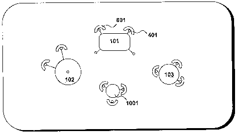
Figure 10 shows a similar view to Figure 9, with the addition of some
drums.
Written Description of the Best Mode for Carrying out the Invention
Figure 1
Figure 1 shows a drum kit. When a drum kit is being played, drums
such as bass drum 101, hi-hat 102, snare drum 103, and crash cymbal 104
are subjected to a significant amount of force. Because of this force exerted,
support feet such as feet 105 and 106 of bass drum 101,and feet 107 and 103
of snare drum 103 can cause damage (such as scratching or marking) to the
underlying floor. Many drum kits are frequently moved to different performing
venues, and it is highly undesirable to cause damage to the floor of any of
these venues.
To prevent damage to floors, many drummers currently have a piece of
carpet or similar that they transport along with their drum kit to each venue,
and place underneath the drum kit to prevent damage. This can be a piece of
ordinary household carpet, but specialist drummers carpets are also available.
Figure 2
Figure 2 shows bass drum 101, and two of its support feet 106 and 201.
Bass drum 101 is placed on carpet 203, which protects floor 204. Because a
bass drum is generally played with a pedal (as is a hi-hat such as 102) when
the pedal is depressed, force is exerted onto the skin 202 of bass drum 101.
This force causes bass drum 101 to move away from the drummer. This is
known as drum creep, and is a common problem known to drummers.
Whilst carpet 203 prevents damage to floor 204, it does not eliminate
drum creep.

CA 02632863 2008-06-02
WO 2007/063303 PCT/GB2006/004464
3
Figure 3
Figure 3 shows a cross section of bass drum 101 in use. When the
drummer's foot 301 presses on to pedal 302, mallet 303 hits drum skin 202.
This causes a significant force in the direction of arrow 304. This
illustrates the
problem of drum creep.
Figure 4
In order to prevent drum creep, rigid foot locators are provided such as
that shown in Figure 4. Foot locator 401 is, in a preferred embodiment,
substantially C-shaped. In a preferred embodiment foot locator 301 is made
from a light-weight metal alloy or a strong plastics material. Foot locator
401
has two holes 402 and 403, designed such that each will receive a connector
to attach foot locator 401 to a carpet or similar substrate. Foot locators
such as
401 are configured to be attached to a carpet such as 203 in order to prevent
drum creep, and this is described with reference to Figure 5 below.
Figure 5
Figure 5 shows a cross-section through apparatus according to an
embodiment of the present invention. Foot locator 401 is shown along with
carpet 203 which has an upper surface 501 and an under surface 502.
Although in this embodiment substrate 203 is a carpet, it is appreciated that
in
alternative embodiments a different flexible substrate could be used, such as
rubber matting. Foot locator 401 is firmly secured to carpet 203 by, in this
embodiment, two connectors 503 and 504.
Connector 503 consists of screw 505 and jet nut 506 and connector
504 consists of screw 507 and jet nut 508. Jet nut 506 is pushed into hole 509
in carpet 203. Screw 505 passes through hole 402 in foot locator 401, and its
thread interacts with the thread inside jet nut 506. Similarly, jet nut 508 is
pushed into hole 510 in carpet 203 and screw 507 passes through hole 403 in
foot locator 401. In a preferred embodiment, holes 509 and 510 in carpet 203
are made using an electric drill.

CA 02632863 2008-06-02
WO 2007/063303 PCT/GB2006/004464
4
With jet nuts 506 and 508 in their respective holes 509 and 510, and
screws 505 and 507 in holes 402 and 403, screws 505 and 507 can be
tightened. In a preferred embodiment, this is done with an Allen key. When
screws 505 and 507 are fully tightened, jet nuts 506 and 508 are pulled into
carpet 203, such that they compress under surface 502, and therefore do not
protrude from the under surface 502 of carpet 203. This is shown in Figure 6.
Figure 6
Figure 6 shows a cross-section of the apparatus according to the
l'o present invention, when ready for use. In a preferred embodiment, upper
layer
501 of carpet 203 has a soft finish, and under layer 502 has a rubberised, non-
slip type surface. Jet nut 506 can be seen to be pulling under layer 502
upwards, towards foot locator 401. Because, in a preferred embodiment, under
surface 502 is non-slip, carpet 203 does not move. Also, because jet nut 506
(or indeed any other part of the apparatus), does not protrude from said under
surface no part of the apparatus marks or damages the floor below.
In this way, foot locators can be attached to a drummers carpet, and
this can be put down in any location without concern about damaging the floor.
Figure 7
Figure 7 shows a plan view of foot locator 401 fixed to carpet 203.
Support foot 106 is shown located within foot locator 401. Because foot
locator
401 is secured firmly to carpet 203, when a force (shown by arrow 701) is
exerted on support foot 106, as a result of bass drum 101 being played, foot
locator 401 prevents backward movement of the supported drum 1'01.
Therefore this apparatus eliminates drum creep.
Figure 8
Figure 8 shows a front view of bass drum 101 on carpet 203, with two.
foot locators 401 and 801 in position behind support feet 106 and 201
respectively.

CA 02632863 2008-06-02
WO 2007/063303 PCT/GB2006/004464
Figure 9
Figure 9 shows a carpet, such as carpet 203, with a number of foot
locators positioned across it.
5 Every drummer has their own configuration of drum kit which they
prefer to play with. Because foot locators such as 401 are, in a preferred
embodiment, permanently attached to carpet 203, their position represents the
configuration of drums for a particular performer. For example, the position
of
foot locators 801 and 401 specify the location for bass drum 101. In addition,
foot locators 901, 902 and 903 could, for example, define the location for
snare drum 103.
In order to assemble apparatus as shown in Figure 8, a performer
would first set up his drum kit, on the carpet, into his preferred
configuration.
The positions of support feet such as feet 105, 106, 107 and 108 would then
be marked onto carpet 203. From these markings, a foot locator would be
positioned at each marked location and secured into position. In this
embodiment, this is achieved by drilling a hole through the carpet for each
connector, then fixing the locator to the carpet with the connectors.
In the present embodiment, foot locators such as 401, 801, 901, 902
and 903 are made from a material to co-ordinate with the drum kit. However, in
an alternative embodiment, each of the foot locators could be colour-coded.
This .could mean for example, that locators 801 and 401 were coded in purple,
whilst locators 901, 902 and 903 could be coded in pink. Support feet 106 and
201 of bass drum 101 could therefore also be coded in purple so as to match
with locators 801 and 401. Similarly, support feet 107 and 108 of snare drum
103 could be coded in pink to co-ordinate with locators 901, 902 and 903.
Alternatively, the pieces of drum kit may not be colour-co-ordinated, but a
list
may be provided stating for example that the bass drum location is defined by
purple locators and the snare drum location is defined by pink locators.
Figure 10

CA 02632863 2008-06-02
WO 2007/063303 PCT/GB2006/004464
6
Figure 10 shows a similar view to Figure 9, with the addition of some
drums placed into position. Bass drum 101 has been located so that its
support feet 201 and 106 are positioned inside locators 801 and 401.
Similarly,
snare drum 103, hi-hat 102 and drummer's stool 1001 are positioned with their
respective locators.
A further advantage of the present invention is therefore that once the
locators have been secured to the carpet, very little skill is required in
order to
set up the drum kit into the performer's own preferred configuration. The
carpet, with locators attached, is simply laid on the floor and then the drums
are fitted in according to the positions of the foot locators. This
significantly
reduces set up time for the drummer, and is therefore a very efficient method.
It also allows an unskilled assistant to set up the drums on behalf of the
drummer.

Representative Drawing
A single figure which represents the drawing illustrating the invention.
Administrative Status

2024-08-01:As part of the Next Generation Patents (NGP) transition, the Canadian Patents Database (CPD) now contains a more detailed Event History, which replicates the Event Log of our new back-office solution.

Please note that "Inactive:" events refers to events no longer in use in our new back-office solution.

For a clearer understanding of the status of the application/patent presented on this page, the site Disclaimer , as well as the definitions for Patent , Event History , Maintenance Fee  and Payment History  should be consulted.

Event History

Description Date
Application Not Reinstated by Deadline 2011-11-30
Time Limit for Reversal Expired 2011-11-30
Deemed Abandoned - Failure to Respond to Maintenance Fee Notice 2010-11-30
Inactive: Cover page published 2008-09-22
Inactive: Notice - National entry - No RFE 2008-09-18
Inactive: Inventor deleted 2008-09-18
Inactive: First IPC assigned 2008-07-05
Application Received - PCT 2008-07-04
National Entry Requirements Determined Compliant 2008-06-02
Application Published (Open to Public Inspection) 2007-06-07

Abandonment History

Abandonment Date Reason Reinstatement Date
2010-11-30

Maintenance Fee

The last payment was received on 2009-11-10

Note : If the full payment has not been received on or before the date indicated, a further fee may be required which may be one of the following

  • the reinstatement fee;
  • the late payment fee; or
  • additional fee to reverse deemed expiry.

Patent fees are adjusted on the 1st of January every year. The amounts above are the current amounts if received by December 31 of the current year.
Please refer to the CIPO Patent Fees web page to see all current fee amounts.

Fee History

Fee Type Anniversary Year Due Date Paid Date
Basic national fee - standard 2008-06-02
MF (application, 2nd anniv.) - standard 02 2008-12-01 2008-06-02
MF (application, 3rd anniv.) - standard 03 2009-11-30 2009-11-10
Owners on Record

Note: Records showing the ownership history in alphabetical order.

Current Owners on Record
IAN BASKERVILLE
Past Owners on Record
None
Past Owners that do not appear in the "Owners on Record" listing will appear in other documentation within the application.
Documents

To view selected files, please enter reCAPTCHA code :


To view images, click a link in the Document Description column. To download the documents, select one or more checkboxes in the first column and then click the "Download Selected in PDF format (Zip Archive)" or the "Download Selected as Single PDF" button.

List of published and non-published patent-specific documents on the CPD .

If you have any difficulty accessing content, you can call the Client Service Centre at 1-866-997-1936 or send them an e-mail at CIPO Client Service Centre.


Document
Description 
Date
(yyyy-mm-dd) 
Number of pages   Size of Image (KB) 
Description 2008-06-01 6 256
Claims 2008-06-01 3 113
Drawings 2008-06-01 10 109
Abstract 2008-06-01 1 58
Representative drawing 2008-09-18 1 6
Notice of National Entry 2008-09-17 1 194
Courtesy - Abandonment Letter (Maintenance Fee) 2011-01-24 1 172
Reminder - Request for Examination 2011-08-01 1 118
PCT 2008-06-01 2 70