Note: Descriptions are shown in the official language in which they were submitted.
CA 02632980 2008-05-30
Structural part arrangement
This invention relates to a structural part comprising first and second first
and second
structural parts wit4 surface contours and intended to be joined by plastic
deformation at
defined weld spots. The invention also relates to a method of joining such
parts.
It is known from the prior art that strength-oriented design of connections
which are
produced by plastic deformation, especially by ultrasound welding, need to be
planned
appropriately by selection of the position of the weld spot, the geometry of
the rivet pin,
and the geometry of the opening into which the rivet pin is inserted.
Depending on the
position of the weld spot on the structural part, changes have to be made in
the geometry
of both structural parts being joined.
DE 10 2005 036 249 Al shows a structural part arrangement assembled from a
sheet
metal piece and a plastic piece. The sheet metal piece and the plastic piece
are joined
together by plastic deformation of a rivet pin, integrated as one piece with
the plastic
piece, while the plastic material of the plastic piece penetrates an opening
in the metal
piece along a direction of penetration and is secured by a rivet head produced
by the
plastic deformation. The region of the metal piece surrounding the opening
serves as an
abutment for a shoulder of the rivet pin.
In the joining process, a sonotrode is placed perpendicularly on the rivet
pin. Thanks to
the action of ultrasound, the rivet pin is plasticized and reaches behind the
upward
protruding edge of the opening in the metal piece.
Considerable tolerance departures may result when the structural parts being
joined have
complicated surface contours.
Therefore, the problem of the invention is to create a structural part
arrangement whose
weld spots lie in the assigned tolerance zone for the fabrication.
According to the present invention there is provided a structural part
arrangement
comprising first and second structural parts with surface contours and
intended to be
joined by plastic deformation at defined weld spots, a rivet pin projecting
from the first
structural part and penetrating an opening in the second structural part, said
rivet pin
having a shoulder, an abutment portion on said second part surrounding the
opening and
providing on its underside an abutment for the shoulder of the rivet pin, and
said
1
CA 02632980 2008-05-30
abutment portion presenting on its upperside a flat stopping surface at least
partially
offset in height relative to the adjoining surface contour of the second
structural part.
It will be understood that the orientations are relative to assist in
understanding the
invention and are not intended to be limiting.
The structural part arrangement thus comprises two structural parts, which can
be joined
together by plastic deformation, especially by ultrasound welding, at defined
weld spots.
The material properties of the two structural parts should be able to melt
together. It is
arranged that a rivet pin projects from the first structural part and
penetrates an opening in
the second structural part, while a region surrounding the opening is
configured as an
abutment for a shoulder of the rivet pin. For a reproducible joint, the
abutment is
fashioned as a flat stopping surface, with at least partial offset in height
relative to the
adjoining surface contour of the second structural part. This has the
advantage that a flat
bearing surface to form the rivet head will always be present, at least in the
region of the
weld spots, even when regions of the joint are irregular. This flat stopping
surface can
also be termed a plateau, since it generally has a noticeably elevated, i.e.,
projecting
position relative to the adjoining regions.
Advantageously, the flat stopping surface can be integrated in a surface
deformation,
which can be configured in particular as a round protrusion. The diameter of
the plateau
depends on the sonotrodes used. However, the pin should be at the same height
at each
weld spot.
The surface deformation can be elevated with respect to the surrounding
surface contour.
That is, it stands above the surface of the second structural part.
In order to have sufficient material available for a fusing together, i.e.,
for the coalescence
of materials, a round collar can surround the opening.
In order to close the opening with material, the rivet pin should extend above
the opening
by a slight amount.
For a stiff joint, it is sufficient for the rivet pin to be tubular in
configuration.
The shoulder of the tubular rivet pin can be formed by cross ribs, which
adjoin the rivet
pin peripherally.
2
CA 02632980 2008-05-30
To simplify the joining process, the rivet pin can be beveled at the upper
edge.
Advantageously, the dimensions of the rivet pin are configured to make an
exact fit with
the opening. Thus, the two parts being joined can be placed one on the other
and be held
together even before the actual joining process.
It has been found that the distances between the weld spots should be at least
60 mm. This
distance depends primarily on the dimensions of the welding unit.
It will thus be appreciated that the first structural part is fitted with at
least one rivet pin,
which is suitable for joining to a second structural part, having an opening.
The rivet pin
has a shoulder, which bears against an abutment, the shoulder being configured
to
correspond to the abutment.
The second structural part is outfitted with an opening which is suitable for
the rivet pin.
A region surrounding the opening is configured as an abutment for a shoulder
of the rivet
pin, the abutment being configured as a flat stopping surface, which has at
least partial
offset in height relative to the adjoining surface contour of the second
structural part.
The invention will now be described in more detail, by way of example only,
with
reference to the accompanying drawings, in which:-
Fig. 1 is a top view of the back side of two structural parts joined together
by ultrasound
welding,
Fig. 2 is a perspective view of a weld spot per Fig. 1,
Fig. 3 is a cross sectional representation per line III-III in Fig. 2,
Fig. 4 is a detailed representation of a rivet pin in perspective view,
Fig. 5is a detailed representation of a surface protrusion in perspective
view,
Fig. 6 shows the surface protrusion on an uneven surface of the second
structural part in
top view,
Fig. 7 shows the surface protrusion of Fig. 6 in a perspective view, from the
front at a
slant,
Fig. 8 is a side view of a first structural part with a plurality of rivet
pins,
Fig. 9 is a top view of a rivet pin per Fig. 8,
3
CA 02632980 2008-05-30
Fig. 10 is a detailed representation of the rivet pin in a slanted front view
per Fig. 9, and
Fig. 11 is a section along line XI-XI in Fig. I through a weld spot.
Figure 1 shows a first structural part 1 and a second structural part 2, which
are joined to
each other at weld spots 3, 4, 5, 6, and 7. The two structural parts 1 and 2
in this
embodiment are a front side paneling, although it will be appreciated that
they could be
any such parts that need to be joined together. The structural part 2 is bent
at the top in the
transition region to structural part I and thus follows the contour of
structural part 1.
Figure 2 shows the weld spot 4 more closely. As can be seen, the weld spot
with its rivet
head 8 is raised above the surface of structural part 2. The rivet head 8 is
produced by the
action of ultrasound vibrations, which are generated by a sonotrode (not shown
here). The
form of such a sonotrode will be found, for example, in DE 100 46 451 Al. Due
to the
plasticization during the ultrasound welding and the form of the sonotrode,
the rivet head
8 has a bulge 10, which has a depression 11 in the middle.
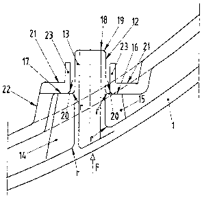
Figure 3 shows more closely the construction of the two parts in the nonwelded
state.
A rivet pin 12, which is tubular in shape projects from the first structural
part 1. The rivet
pin 12 is situated in an upstanding position, regardless of the trend or
surface contour of
the first structural part 1. Cross ribs 14, 15 stand off from the tubes 13.
The cross ribs 14,
15 are fitted with a shoulder 16, 17, serving to bear against the second
structural part 2.
The binding of the rivet pin 12 both to the cross ribs 14 and 15 and also to
the structural
part I itself are provided with a radius r to counteract notch effects when
the feed units of
the ultrasound apparatus are put in place. A bevel 19 is provided at the upper
closing edge
18 of the rivet pin, facilitating the insertion of the rivet pin into the
opening in the second
structural part.
The second structural part 2 has a geometrically concave surface, whose
regular trend is
shown by a broken line and would in fact run parallel to the contour of
structural part 1.
According to an embodiment of the invention, the region 21 enclosing the
opening is
fashioned as a plateau, i.e., a flat abutment surface for the shoulders 16, 17
of the rivet pin
12. When the rivet pin is introduced in the direction F, the structural part I
is shifted until
the shoulders 16, 17 come to rest against the underside of the flat abutment
surface 21.
The abutment surface or_ the plateau 21 are integrated into a round protrusion
22, which is
4
CA 02632980 2008-05-30
more or less elevated depending on the surface contour of the structural part
2. The
construction of the round protrusion 22 is geometrically the same at all weld
spots, which
improves the reproducibility of the ultrasound connections.
A protruding round collar 23 surrounds the edge of the opening 20, and while
in the
joined, but not welded state, the upper closing edge of the rivet pin 12 rises
above the
round collar 23.
The rivet pin is illustrated in Fig. 4, showing that two additional cross ribs
24 and 25 are
provided diametrically to the cross ribs 14 and 15. The distance from the
shoulders 16,
17, 26, 27 to the upper closing edge 18 depends on the material being
plasticized. It can
be arranged to have a locking action in addition, at least for some of the
weld spots, so as
to assure at least some degree of a connection when one part is placed on the
other, to
facilitate the handling of the two parts.
Figure 5 shows, in a detail view, the protrusion 22 with the rivet pin 12
inserted. It is
apparent that the upper closing edge 18 of the rivet pin 12 extends beyond the
round
collar 23 of the protrusion 22. The sonotrode comes from the direction of the
arrow F, to
plastically deform the rivet pin 12 and protrusion 22 to each other.
Fig. 6 and 7 show a round protrusion, which is situated at a deeply indented
and thus
especially hard to reach location of the first structural part. It is apparent
that the round
protrusion 22 has created a flat stopping surface 21 for the sonotrode of the
ultrasound
welding apparatus.
The representations of Fig. 8, 9 and 10 show a plurality of rivet pins 12. The
shoulders
16, 17, 26, 27 of the cross ribs of the rivet pins arranged in a row all end
at the same
height, in order to permit the individual parts to be joined with a reliable
and proper
assembly process.
Figure 11 shows a weld spot in the final joined form. The two structural parts
are
materially joined to each other. Since the same materials have been used for
structural
part 1 and 2, the parts 1 and 2 can no longer be distinguished from each other
in the
joined state. No transitional edges can be discerned.
The above described configuration of the rivet pin and round pin produce
welded
connections of very good quality, both in terms of fabrication technique and
noise. The
CA 02632980 2008-05-30
round protrusions should be the same at all weld spots. To improve the welded
connection of the two structural parts, as described above, a round collar is
provided at
the opening, which has the effect of an improved quality thanks to direct
fusion of the two
structural parts with each other, as opposed to the formation of a mere rivet
head. If the
materials of the parts being welded do not correspond, the round collar need
not be
produced. The rivet pins should be configured with a radius in the binding to
the carrier,
in order to assure a better binding to the carrier and avoid notch effects
when the feed
units and the sonotrodes are put in place. Bevels should preferably be formed
at the upper
end of the rivet pin to achieve a better plasticization, for then a smaller
amount of molten
material has the effect of a faster melting and a more uniform heating.
At least two round rivets per structural part should be higher thaii the other
round pins by
a certain amount, such as 2 mm, for a reliable and proper joining capability.
Ideally, the
two larger round pins are two oppositely situated weld spots. So that the
parts once
joined, which occurs in part outside of the abutment, do not fall apart again
when inserted
in the abutment, the round pins should additionally be ribbed for fitting or
be joined
firmly by separate locking points. Independently of this, a movement such as a
turning of
the structural parts should be possible, without the two parts falling apart
once again.
Embodiments of the invention thus provide a flat bearing surface, namely a
plateau, to
form the rivet head for each weld spot. It has been stated that a diameter of
around 16 mrn
is especially effective. Regardless of the configuration of the structural
part, it is now
possible to provide flat bearing surfaces for the sonotrodes and the feed
units.
Since, for proper fusion, the structural parts are pressed together via rivet
holders during
the welding process, additional suitable flat surfaces can be provided for
this in the
vicinity of the weld spots. Ideally, the surfaces should continue the same
level for the
welding pins. Furthermore, it must be possible to weld all weld spots by a
separate feed
unit for quality assurance of the weld spot and the possibility of adjusting
it. Therefore, a
distance of at least 60 mm to 65 mm between the weld spots is recommended.
6