Language selection

Search

Patent 2633165 Summary

Third-party information liability

Some of the information on this Web page has been provided by external sources. The Government of Canada is not responsible for the accuracy, reliability or currency of the information supplied by external sources. Users wishing to rely upon this information should consult directly with the source of the information. Content provided by external sources is not subject to official languages, privacy and accessibility requirements.

Claims and Abstract availability

Any discrepancies in the text and image of the Claims and Abstract are due to differing posting times. Text of the Claims and Abstract are posted:

  • At the time the application is open to public inspection;
  • At the time of issue of the patent (grant).
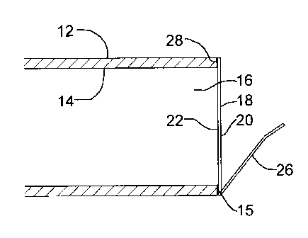
(12) Patent: (11) CA 2633165
(54) English Title: SEAL FOR PRESSURE TESTING A PLUMBING INSTALLATION AND METHOD OF USE THEREOF
(54) French Title: JOINT D'ETANCHEITE PERMETTANT DE VERIFIER LA PRESSION D'UNE INSTALLATION DE PLOMBERIE, ET METHODE D'UTILISATION CONNEXE
Status: Granted and Issued
Bibliographic Data
(51) International Patent Classification (IPC):
  • F16L 55/10 (2006.01)
  • E03C 01/00 (2006.01)
  • F16L 01/00 (2006.01)
  • F16L 55/115 (2006.01)
  • G01M 03/26 (2006.01)
(72) Inventors :
  • COSCARELLA, GABE (Canada)
(73) Owners :
  • GABE COSCARELLA
(71) Applicants :
  • GABE COSCARELLA (Canada)
(74) Agent: NATHAN V. WOODRUFFWOODRUFF, NATHAN V.
(74) Associate agent:
(45) Issued: 2015-05-26
(22) Filed Date: 2008-05-29
(41) Open to Public Inspection: 2009-11-29
Examination requested: 2013-05-06
Availability of licence: N/A
Dedicated to the Public: N/A
(25) Language of filing: English

Patent Cooperation Treaty (PCT): No

(30) Application Priority Data: None

Abstracts

English Abstract

A method for testing the integrity of a plumbing system. A first step involves affixing a seal with a releasable adhesive over a component of the plumbing system having a bore to occlude the bore. A second step involves charging the plumbing system with a fluid.


French Abstract

Une méthode pour vérifier lintégrité dune installation de plomberie. Une première étape comporte la pose dun joint détanchéité avec un adhésif décollable sur un composant de linstallation de plomberie avec un calibre pour occlure lalésage. Une seconde étape comporte de charger linstallation de plomberie avec un fluide.

Claims

Note: Claims are shown in the official language in which they were submitted.

What is claimed is:
1. A method for testing the integrity of a plumbing system, the method
comprising the
steps of:
affixing a seal with a releasable adhesive to a component of the plumbing
system
having a bore to occlude the bore, the seal having a pull tab;
charging the plumbing system with a fluid; and
applying a force to the pull tab, the force being sufficient to release the
seal by
releasing the adhesive.
2. The method of claim 1, wherein the step of charging the plumbing system
with a fluid
results in pressurizing the plumbing system to between about 5 psi to about 15
psi.
3. The method of claim 1, wherein the step of charging the plumbing system is
performed
with one of water, air or inert gas.
4. The method of claim 1, wherein the component of the plumbing system is a
pipe or a
fitting.
5. For use in testing plumbing system integrity, a seal, the seal comprising:
a gas and water resistant body having a perimeter, a periphery, a front face,
and a
back face;
an adhesive on at least the periphery of the back face; and
a tab extending from the perimeter or front face, such that in use, the body
is
releasably affixed to occlude a bore of a component of a plumbing system, the
adhesive
being selected to release when a predetermined force is applied to the tab by
a user.
6. The seal of claim 5, wherein the adhesive can withstand a pressure of
between about 5
psi to about 15 psi.
6

7. The seal of claim 5, wherein the body is comprised of a metal, a plastic
polymer, or
combination thereof.
8. The seal of claim 5, wherein the body has a sealing ring on the back face
and the
adhesive is positioned on the sealing ring.
9. The seal of claim 8, wherein the body and the sealing ring are separate,
and are
secured by adhesive.
10. The seal of claim 7, wherein the component of the plumbing system is a
pipe or a
fitting.
11. A combination for use in testing plumbing system integrity, comprising:
a seal, the seal comprising:
a gas and water impermeable body, having a perimeter, a periphery, a
front face and a back face;
a tab extending from the perimeter or front face;
an adhesive on at least the periphery of the back face or on the perimeter;
and
a component of a plumbing system having a bore therethrough, wherein the seal
is
releasably affixed to an inner wall or end wall of the component of the
plumbing system
with the adhesive, the seal covering the bore, thereby releasably occluding
the bore, the
adhesive being selected to release upon application of a predetermined force
to the tab.
12. The combination of Claim 11, wherein the adhesive can withstand a pressure
of
between about 5 psi to about 15 psi and yet release when a force is applied to
the tab by a
user.
13. The combination of Claim 11, wherein the component of the plumbing system
is a
pipe or a fitting.
7

Description

Note: Descriptions are shown in the official language in which they were submitted.


CA 02633165 2008-05-29
TITLE
[0001] Seal for pressure testing a plumbing installation and method of use
thereof
FIELD
[0002] The technology relates to a seal and method for assessing integrity of
a
plumbing system. More specifically, the technology is a low cost resilient,
releasable
sealing seal.
BACKGROUND
[0003] During the final stages of plumbing, a test must be conducted to ensure
the
integrity of the plumbing system. This requires charging the system such that
it becomes
pressurized, during which time the plumber looks for leaks. The system must be
closed
in order to make the assessment. Once the integrity is assured, the means for
plugging
the system is removed.
[0004] What is required is a simple, inexpensive seal that can withstand the
pressures
needed to test plumbing installations, while being readily removable after the
testing is
completed.
SUMMARY
[0005] According to one aspect there is provided a method for testing the
integrity of
a plumbing system. A first step involves affixing a seal with a releasable
adhesive to a
component of the plumbing system having a bore to occlude the bore. A second
step
involves charging the plumbing system with a fluid.
[0006] According to another aspect there is provided a releasable seal that
can be
affixed to a component of a plumbing system, whether to a plumbing fitting, at
the end of
a pipe, along the length of the pipe, etc. to permit testing for leakages in
the plumbing
system.
BRIEF DESCRIPTION OF THE DRAWINGS
1

CA 02633165 2008-05-29
[0007] These and other features will become more apparent from the following
description in which reference is made to the appended drawings, the drawings
are for the
purpose of illustration only and are not intended to be in any way limiting,
wherein:
FIG. 1 is a front plan view of a seal for testing the integrity of a plumbing
installation.
FIG. 2 is a rear plan view of the seal of FIG. 1.
FIG. 3 is a side elevation view in section of the seal of FIG. 1 installed on
a pipe.
FIG. 4 is a side elevation view in section of the seal of FIG. 1 installed in
a
plumbing installation.
FIG. 5 is a side elevation view in section of the seal partially removed.
FIG. 6 is a side elevation view in section of an alternative embodiment of the
seal.
FIG. 7 is a side elevation view in section of a further alternative embodiment
of
the seal.
FIG. 8 is a side elevation view in section of a further alternative embodiment
of
the seal.
DETAILED DESCRIPTION
[0008] A seal, generally referred to as 10, is shown in FIG. 1 and 2. The seal
10 has
a body 18 with having a front face 20, a back face 22, a perimeter 24, and a
tab 26
extending from the body 18 on the front face 20. The tab 26 may be integral or
may be a
separate component that is attached to the body 18. The tab 26 is preferably
connected to
the perimeter 24 of body 18. The body 18 is at least resistant, if not
impermeable, to the
fluid to be used for testing purposes, such as water, air, gas, etc. An
adhesive 28 is
disposed on body 18 to secure it to a component of a plumbing system. For
convenience,
a plumbing pipe 12 is used in the description below and in the drawings.
However, it
will be understood that body 18 may also be secured to other suitable
components with a
bore, such as plumbing fittings (not shown), and that in other embodiments,
plumbing
pipe 12 may be replaced by these other components. As shown in FIG. 2, the
adhesive
28 is applied to a periphery 30 of the back face 22 which is intended to
contact a
plumbing pipe 12, as shown in FIG. 3. For clarity, the term periphery is used
to include
2

CA 02633165 2008-05-29
any outer portion of body 18 intended to contact plumbing pipe 12, and
includes at least
one of the peripheral region on the back face 22, the peripheral region of a
peripheral
annulus portion 34 of the back face 22 and the perimeter of the peripheral
annulus 34.
For storage and transportation prior to use, adhesive 28 may be covered by a
tear-away or
peel-away strip (not shown). Alternatively, adhesive 28 and body 18 may be
stored
separately, with adhesive 28 being applied to body 18 immediately prior to
use, or
adhesive may be activated by applying, for example, water or other substances.
[0009] In use, referring to FIG. 3 the body 18 of seal 10 is placed over a
plumbing
pipe 12 that has an inner wall 14, an end 15 and a bore 16. The seal 10 is
positioned such
that the adhesive 28 contacts the end 15 of the plumbing pipe 12, to cover the
bore 16.
Pressure or heat is applied to cause the adhesive 28 to adhere to the end of
the plumbing
pipe 12. Referring to FIG. 4, plumbing pipe 12 is then installed in a plumbing
system,
generally indicated by reference numeral 17. Once secured, the system 17 is
charged
with fluid such as a gas, such as air, a liquid, such as water, or a mixture
of fluids until
the desired pressure is reached. The integrity of the plumbing can then be
assessed.
Referring to FIG. 5, the seal 10 may be removed once testing has been
completed by
pulling on the tab 26. The adhesive 28 may be designed to withstand pressures
of
between about 5 psi to about 15 psi for some plumbing systems, and to release
when a
force is applied to the tab 26 by a user. This may be done by having a
breakaway
pressure that is greater than the maximum test pressure, or by providing an
adhesive with
a lower shear strength, such that pulling at an angle causes the adhesive to
pull away
from end 15 of pipe 12. In one embodiment, the tab 26 is preferably adjacent
to the
adhesive 28 on an opposite face to more efficiently transfer the force
necessary to release
the adhesive 28. Other designs for a tab 26 that allows the adhesive 28 to be
released will
be apparent to those skilled in the art.
[0010] If the end 15 of the plumbing pipe 12 is not accessible, the seal 10
may also be
placed as shown in FIG. 6. Preferably, the seal 10 is pre-creased, or
otherwise provided
with a lip 38 extending at about right angle to the front face 20 to assist in
positioning the
adhesive 28, such that it contacts the inner wall 14 of the plumbing pipe 12,
covering the
3

CA 02633165 2008-05-29
bore 16. Once in place, pressure or heat is applied to cause the adhesive to
adhere to the
inner wall 14 of the plumbing pipe 12. Once secured, the system is charged
with fluid,
for example a gas, such as air, a liquid, such as water, or a mixture of
fluids until the
desired pressure is reached. The integrity of the plumbing can then be
assessed. At any
time after the integrity of the system has been assessed, the seal 10 is
removed by pulling
on the tab 26 as discussed previously.
[0011] Alternatively, referring to FIG. 7, if the end 15 of the plumbing pipe
12 is not
accessible, such as if pipe 12 is integrally formed with system 17 such that
there is not an
end 15, a flange 40 may be employed. Body 12 is secured to flange 40 by
applying
pressure or heat to cause the adhesive 28 to adhere to flange 40. The flange
40 is then
positioned on the inner wall 14 of the plumbing pipe 12. A pipe 12 (not shown)
is then
welded into system 17, and the pipe is secured to flange 40 , such as by using
the same
solvent that secures pipe 12 into system 17. Once secured, the system is
charged with a
gas, a mixture of gases or a fluid, most commonly water until the desired
pressure is
reached. The integrity of the plumbing can then be assessed. At any time after
the
integrity of the system has been assessed, the seal 10 is removed by pulling
on the tab 26
as discussed previously.
[0012] Alternatively, referring to FIG. 8, a seal 10 similar to that depicted
in FIG. 6
may be used, where adhesive 28 is positioned on periphery 24 of body 12, which
is bent
to form a sidewall-type structure.
[0013] The foregoing is a description of embodiments of the technology. As
would
be known to one skilled in the art, variations that do not change the scope of
the invention
are contemplated. For example, the seal body may be made of any suitable
material that
is able to withstand the pressure, as well as to be impervious to water and
air, or at least
impervious enough to permit testing of the plumbing system, for example, but
not limited
to, various plastic polymers, laminates, plasticized or waxed paper products,
metal. The
adhesive must be able to withstand the pressure exerted on the inner wall of
the body,
while at the same time, be selected to permit a user to pull the body away
from the pipe.
4

CA 02633165 2008-05-29
The adhesive is preferably water insoluble, however, sparingly soluble
adhesives could
be employed. The tab can be any sort of pull tab, as would be known to one
skilled in the
art and may range in shape from a defined tab to an extension of the
perimeter, for
example in the general shape of a triangle. The adhesive may become adhesive
by
exposing it to heat or chemicals, for example. In these instances, a tear-away
would not
be needed.
5

Representative Drawing
A single figure which represents the drawing illustrating the invention.
Administrative Status

2024-08-01:As part of the Next Generation Patents (NGP) transition, the Canadian Patents Database (CPD) now contains a more detailed Event History, which replicates the Event Log of our new back-office solution.

Please note that "Inactive:" events refers to events no longer in use in our new back-office solution.

For a clearer understanding of the status of the application/patent presented on this page, the site Disclaimer , as well as the definitions for Patent , Event History , Maintenance Fee  and Payment History  should be consulted.

Event History

Description Date
Inactive: COVID 19 - Deadline extended 2020-05-14
Common Representative Appointed 2019-10-30
Grant by Issuance 2015-05-26
Inactive: Cover page published 2015-05-25
Pre-grant 2015-03-04
Inactive: Final fee received 2015-03-04
Notice of Allowance is Issued 2014-09-10
Letter Sent 2014-09-10
Notice of Allowance is Issued 2014-09-10
Inactive: Approved for allowance (AFA) 2014-08-19
Inactive: Q2 passed 2014-08-19
Amendment Received - Voluntary Amendment 2014-07-02
Inactive: S.30(2) Rules - Examiner requisition 2014-01-31
Inactive: Report - No QC 2014-01-30
Letter Sent 2013-05-08
Request for Examination Requirements Determined Compliant 2013-05-06
Request for Examination Received 2013-05-06
All Requirements for Examination Determined Compliant 2013-05-06
Inactive: Office letter 2011-05-16
Letter Sent 2010-07-08
Inactive: Office letter 2010-03-23
Inactive: Cover page published 2009-11-29
Application Published (Open to Public Inspection) 2009-11-29
Inactive: IPC assigned 2009-11-20
Inactive: IPC assigned 2009-07-29
Inactive: First IPC assigned 2009-07-29
Inactive: IPC assigned 2009-07-29
Inactive: IPC assigned 2009-02-16
Application Received - Regular National 2008-07-08
Inactive: Filing certificate - No RFE (English) 2008-07-08
Small Entity Declaration Determined Compliant 2008-05-29

Abandonment History

There is no abandonment history.

Maintenance Fee

The last payment was received on 2015-02-11

Note : If the full payment has not been received on or before the date indicated, a further fee may be required which may be one of the following

  • the reinstatement fee;
  • the late payment fee; or
  • additional fee to reverse deemed expiry.

Patent fees are adjusted on the 1st of January every year. The amounts above are the current amounts if received by December 31 of the current year.
Please refer to the CIPO Patent Fees web page to see all current fee amounts.

Fee History

Fee Type Anniversary Year Due Date Paid Date
Application fee - small 2008-05-29
MF (application, 2nd anniv.) - small 02 2010-05-31 2010-03-02
MF (application, 3rd anniv.) - small 03 2011-05-30 2011-05-02
MF (application, 4th anniv.) - small 04 2012-05-29 2012-05-01
Request for examination - small 2013-05-06
MF (application, 5th anniv.) - small 05 2013-05-29 2013-05-06
MF (application, 6th anniv.) - small 06 2014-05-29 2014-05-05
MF (application, 7th anniv.) - small 07 2015-05-29 2015-02-11
Final fee - small 2015-03-04
MF (patent, 8th anniv.) - small 2016-05-30 2016-05-04
MF (patent, 9th anniv.) - small 2017-05-29 2017-05-08
MF (patent, 10th anniv.) - small 2018-05-29 2018-05-15
MF (patent, 11th anniv.) - small 2019-05-29 2019-05-21
MF (patent, 12th anniv.) - small 2020-05-29 2020-05-22
MF (patent, 13th anniv.) - small 2021-05-31 2021-05-28
MF (patent, 14th anniv.) - small 2022-05-30 2022-05-30
MF (patent, 15th anniv.) - small 2023-05-29 2023-05-10
MF (patent, 16th anniv.) - small 2024-05-29 2024-04-02
Owners on Record

Note: Records showing the ownership history in alphabetical order.

Current Owners on Record
GABE COSCARELLA
Past Owners on Record
None
Past Owners that do not appear in the "Owners on Record" listing will appear in other documentation within the application.
Documents

To view selected files, please enter reCAPTCHA code :


To view images, click a link in the Document Description column. To download the documents, select one or more checkboxes in the first column and then click the "Download Selected in PDF format (Zip Archive)" or the "Download Selected as Single PDF" button.

List of published and non-published patent-specific documents on the CPD .

If you have any difficulty accessing content, you can call the Client Service Centre at 1-866-997-1936 or send them an e-mail at CIPO Client Service Centre.


Document
Description 
Date
(yyyy-mm-dd) 
Number of pages   Size of Image (KB) 
Abstract 2008-05-28 1 7
Description 2008-05-28 5 191
Claims 2008-05-28 3 62
Drawings 2008-05-28 4 39
Representative drawing 2009-11-04 1 5
Claims 2014-07-01 2 60
Representative drawing 2015-04-28 1 5
Maintenance fee payment 2024-04-01 2 39
Filing Certificate (English) 2008-07-07 1 157
Reminder of maintenance fee due 2010-01-31 1 113
Reminder - Request for Examination 2013-01-29 1 117
Acknowledgement of Request for Examination 2013-05-07 1 190
Commissioner's Notice - Application Found Allowable 2014-09-09 1 161
Correspondence 2008-07-07 1 56
Correspondence 2010-01-31 1 40
Correspondence 2010-03-22 1 18
Fees 2010-03-02 1 29
Fees 2010-03-01 1 28
Fees 2010-03-11 1 32
Correspondence 2010-07-07 1 16
Fees 2010-03-02 1 28
Correspondence 2011-03-30 3 155
Correspondence 2011-05-15 1 20
Correspondence 2011-05-15 1 35
Fees 2011-05-01 1 35
Fees 2014-05-04 1 23
Fees 2015-02-10 1 24
Correspondence 2015-03-03 1 36
Maintenance fee payment 2019-05-20 1 24
Maintenance fee payment 2020-05-21 1 25
Maintenance fee payment 2021-05-27 1 25