Language selection

Search

Patent 2633510 Summary

Third-party information liability

Some of the information on this Web page has been provided by external sources. The Government of Canada is not responsible for the accuracy, reliability or currency of the information supplied by external sources. Users wishing to rely upon this information should consult directly with the source of the information. Content provided by external sources is not subject to official languages, privacy and accessibility requirements.

Claims and Abstract availability

Any discrepancies in the text and image of the Claims and Abstract are due to differing posting times. Text of the Claims and Abstract are posted:

  • At the time the application is open to public inspection;
  • At the time of issue of the patent (grant).
(12) Patent Application: (11) CA 2633510
(54) English Title: JET AIR RECOVERY GENERATOR
(54) French Title: GENERATEUR A RECUPERATION D'AIR D'AVION A REACTION
Status: Deemed Abandoned and Beyond the Period of Reinstatement - Pending Response to Notice of Disregarded Communication
Bibliographic Data
Abstracts

English Abstract


A method of generating energy from a discharge of an aircraft comprising the
steps of:
a) providing an air recovery generator assembly having a bladed wheel; and, b)
positioning
the air recovery generator behind the aircraft. The discharged air from the
aircraft then
turns the wheel thereby generating energy. In a preferred aspect of this
invention the bladed
wheel comprises a bladed cylinder wheel and the bladed cylindrical wheel
additionally rotates
a flywheel to store rotational energy therein. A mechanism is provided to move
the bladed
cylindrical wheel from a below ground storage position to an elevated
operational position.


Claims

Note: Claims are shown in the official language in which they were submitted.

I CLAIM:
1) A method of generating energy from a discharge of an aircraft comprising
the steps
of:
a) providing an air recovery generator assembly having a bladed wheel; and,
b) positioning the air recovery generator behind the aircraft;
so that discharged air from the aircraft turns the wheel thereby generating
energy.
2) A method as in claim 1 wherein the bladed wheel comprises a bladed cylinder
wheel.
3) A method as in claim 2 wherein the bladed cylindrical wheel additionally
rotates a
flywheel to store rotational energy therein.
4) A method as in claim 2 further comprising a mechanism to move the bladed
cylindrical wheel from a below ground storage position to an elevated
operational position.
5) A method as in claim 4 wherein the mechanism is covered by a grate so that
a flat
supporting surface is presented above the bladed cylindrical wheel when it is
in a retracted
position and so that discharged air can pass through the grate when it is in
an elevated
position.
7

6) A method as in claim 5 wherein the grate is hinged on a rear side portion
so that if
the grate was inadvertently left open it would close when an aircraft rolled
forwardly
thereover.
7) A method as in claim 6 wherein the bladed cylindrical wheel is carried by a
lower
front side portion of the grate and wherein the generator and flywheel are
carried attached to
a lower rear side portion of the grate so that when the grate is lifted the
bladed wheel is also
lifted.
8) A method as in claim 7 wherein the grate is hinged along a rear side
portion so that
the front side portion of the grate can be swung upwardly lifting the upper
side portion of the
bladed cylindrical wheel above ground to the elevated operational position.
9) A method as in claim 8 wherein the grate is provided with a remotely
controlled lift
mechanism.
10) A method as in claim 8 further comprising a grate counterweight so that
the lift
required to elevate the grate to the operational position is minimized.
11) A method as in claim 10 further comprising a wind catching blade attatched
along
a front side portion of the grate so that discharged air from the aircraft
will automatically
elevate the grate to an operational position.
8

12) A method as in claim 8 further comprising a governor/ clutch assembly
mechanically attached to a shaft of the bladed cylindrical wheel on one end
and a secondary
flywheel on the other end to limit the speed of the bladed cylindrical wheel
when required.
13) A method as in claim 8 further comprising additional jet air recovery
generator
assemblies spaced along the runway.
9

Description

Note: Descriptions are shown in the official language in which they were submitted.


CA 02633510 2008-06-04
JET AIR RECOVERY GENERATOR
FIELD OF THE ZNVENT'ION
This invention relates to energy recovery from wind, More particularly this
invention relates to an apparatus and method for recovering energy from
discharged engine
air when jets takeoff at an airport.
BACKGROIIND OF THE 1NVEIMON
Commercial jets cruise at air speeds exceeding 500 mph. At takeoff air
discharged
from their engines has speeds exceeding 300 mph. The speed of this dischazged
air is
greatest immediateiy behind the engines. At one end of the runway prior to
take off pilots
usually accelerate their engines to full power with, their wheel brakes
engaged in order to
achieve maximum air speed at the other end of the runway in order to Uft off.
This engine
accelerating position for take off is generally the same for aJl planes taking
off. ixnmediately
behind this accelerating position on the runway air is discharged at speeds
exceeding 300
mph. This high velocity air exerts tremendous force and contains much inherent
powe,r.
1

CA 02633510 2008-06-04
OB7LCTS OF THE INVENTION
It is azt object of this invention to disclose a method and apparatus for
capturing
energy contained within this discharge air or propwash_ It is an dbject of
this invention to
disclose a simple apparatus which will generate substantial power from air
discharged from
aircraft. It is yet a further object of this invention to disclose an
apparatus which may be
most advantageously and conveniently positioned immediately behi.ad a jet
positioned for take
off on a runway. It is a final object of this invention to disclose a power
generation
apparatus which is inconspicuously and conveniently positioned beneath the
runway when not
in use, and a power generator which automatically elevates to an in use
position immediately
before an adjacent aircraft accelerates its engines for takeoff.
One aspect of this invention provides for a method of geneTating energy from a
discharge of an aircraft comprising the steps of: a) providing an air recovery
generator
assembly having a bladed wheel; and, b) positioning the air recovery generator
behind the
aircraft. The discharged air from the aircraft then turns the wheel thereby
generating energy.
In a preferred aspect of this invention the bladed wheel comprises a bladed
cylinder
wheel and the bladed cylindrical wheel additionally rotates a flywheel to
store rotational
energy therein.
2

CA 02633510 2008-06-04
In another pre;Ferred aspect of the invention a mechanism to move the bladed
cylindrical whM fzoxn a below ground storage position to an elevated
operational position.
Va.rrxous other objects, advantages and features of this invention will become
apparent to those s1dlled in the art from the following description in
conjunction with the
accompanying drawings.
FIGURES OF THE INVENTION
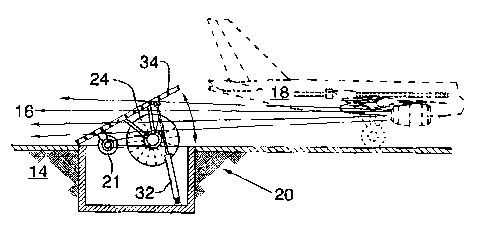
Figure 1 is an elevational view of jet air recovery generator assembly having
a
bladed wheel. The generator assembly is positioned behind a jet aircraft.
Figure 2 is a schematic view of the bladed cylindrical wheel shown in figure
1.
The bladed wheel has integral flywheels. The shaft of the bladed wheel is
attached to a
govemorl clutch assembly which engages a secondary flywheel when required.
Figure 3 is a plan view of a runway showing multiple jet air recovery
generator
assemblies spaced therealong.
The following is a discussion and description of the pzef'erred specific
embodiments
of this invention, such being made with reference to the drawings, wherein the
same
3

CA 02633510 2008-06-04
reference numerals are used to indicate the same or similar parts and/or
structure. It should
be noted that suclt discussion and description is not meant to unduly limit
the scope of the
invention.
DESCMTION OF THE INVFNTION
Turning now to the drawings and more particularly to figure 1 we have an
elevational view of jet air recovery generator assembly 20 having a bladed
wheel 22. The
generator assembly 20 xs positioned bebind a,jet aircraft 18. A method of
generating energy
from a discharge of a jet ai.rcraft 18 comprises the steps of: a) providing a
jet air recovery
generator assembly 20 having a bladed wheel 22; and, b) positioning the jet
air recovery
generator 20 behind the aircraft 18. Discharged air 16 from the aircraft 18
turns the wheel
22 thereby generatirAg energy. Most preferably the bladed wbee122 comprises a
bladed
cylinder 24 and rotates a flywheel 26 to store rotational energy therein.
Figure 2 is a perspective view of the bladed cylindrical wheel shown in figure
1.
The cylindrical bladed wheel 22 additionally rotates a flywbeel 26 to store
rotational energy
therein. In figure 2 the cylindrical bladed wheel is shown, with an integral
17.yw,hee126. The
shaft of the bladed wheel is attached to a governor/ clutch assembly 28 which
engages a
secondary flywheel 30 when required. Irt a preferred embodiment of the
invention a
governor/ clutch assembly 28 is .mechanicatly attached to a shaft of the
bladed wheel 22 and
4

CA 02633510 2008-06-04
to a seco.ndary flywheel 30 to limit the speed of the cylindrical wheel 24
when required. The
govez;n,or/ciutcb assembly 28 engages the secondary flywheel 30 when rpm is
excessive_
As shown in figure 1, a preferred embodiment of the invention, the bladed
cylindrical wheel is most preferably stored and housed below ground. When the
cylindrical
wheel is stored below ground then the assembly 20 further comprises a
mechanism 32 to
move the bladed cylindrical wheel 24 from a below ground storage position to
an elevated
operational position.
Most preferably the mechanism 32 is covered by a grate 34 so that a flat
supporting
surface is presented above the bladed cylindrical wheel 24 when it is in a
retracted position
and also so that discharged air 16 can pass through the grate 34 when it is in
an elevated
position. Most preferably the grate 34 is hinged on a front side portion so
that if the grate
34 was inadvertently left open it would close when an aircraft 18 rolled
forwardly thereover.
In the most preferred embodiment of the invention the bladed cylindrical wheel
24 is carried
by a lower front side portion of the grate 34 and the generator 21 and
flywhee126 are
carried attached to a lower rear side portion of the grate 34 so that when the
grate 34 is lifted
the bladed cylindrical wheel 24 is also lifted.
In a preferred embodiment of the invention the bladed cyl.indzical whee124 is
carza.ed by a lower front side portion of the grate 34 and the generator 21
and flywheel 26
are carried attached to a lower rear side portion of the grate 34 so that when
the grate 34 is

CA 02633510 2008-06-04
lifted the bJ.aded cylindricat wheel 24 is also lifted. The grate 34 is hinged
along a rear side
portion so that the front side portion of the grate 34 can be swung upwardly
Iifting the upper
side portion of the bladed cylindrical wheel 24 above ground 14 to the
elevated operational
position. The grate 34 is provided with a remotely controlled lift mechanism
32.
In the most preferred embodiment, the invention further comprises a grate
counterweight 33 so that the lift required to elevate the grate 34 to the
operational position is
minimized. In the most preferred embodiment, the invention also comprises a
wind catching
blade 36 attatched along a fzont side portion of the grate 34 so that
discharged air from the
aircraft 18 will automatically elevate the grate 34 to an operational
position.
Figure 3 is a plan view of a runway 12 showing multiple jet air recovery
generator
assemblies spaced therealong.
While the invention has been described with preferred specific embodiments
thereof, it will be understood that this description is intended to illustrate
and not to limit the
scope of the invention, which is defxned by the following claims.
6

Representative Drawing
A single figure which represents the drawing illustrating the invention.
Administrative Status

2024-08-01:As part of the Next Generation Patents (NGP) transition, the Canadian Patents Database (CPD) now contains a more detailed Event History, which replicates the Event Log of our new back-office solution.

Please note that "Inactive:" events refers to events no longer in use in our new back-office solution.

For a clearer understanding of the status of the application/patent presented on this page, the site Disclaimer , as well as the definitions for Patent , Event History , Maintenance Fee  and Payment History  should be consulted.

Event History

Description Date
Inactive: IPC expired 2024-01-01
Inactive: IPC deactivated 2017-09-16
Inactive: IPC assigned 2017-01-01
Inactive: IPC expired 2017-01-01
Inactive: IPC deactivated 2016-01-16
Inactive: IPC assigned 2016-01-01
Inactive: First IPC assigned 2016-01-01
Inactive: IPC expired 2016-01-01
Time Limit for Reversal Expired 2013-06-04
Application Not Reinstated by Deadline 2013-06-04
Inactive: Adhoc Request Documented 2013-03-06
Deemed Abandoned - Failure to Respond to Maintenance Fee Notice 2012-06-04
Application Published (Open to Public Inspection) 2009-12-04
Inactive: Cover page published 2009-12-03
Inactive: First IPC assigned 2009-05-13
Inactive: IPC assigned 2009-05-13
Inactive: IPC assigned 2009-02-17
Inactive: Office letter 2008-07-15
Application Received - Regular National 2008-07-10
Filing Requirements Determined Compliant 2008-07-10
Inactive: Filing certificate - No RFE (English) 2008-07-10
Small Entity Declaration Determined Compliant 2008-06-04

Abandonment History

Abandonment Date Reason Reinstatement Date
2012-06-04

Maintenance Fee

The last payment was received on 2008-06-04

Note : If the full payment has not been received on or before the date indicated, a further fee may be required which may be one of the following

  • the reinstatement fee;
  • the late payment fee; or
  • additional fee to reverse deemed expiry.

Please refer to the CIPO Patent Fees web page to see all current fee amounts.

Fee History

Fee Type Anniversary Year Due Date Paid Date
MF (application, 2nd anniv.) - small 02 2010-06-04 2008-06-04
MF (application, 3rd anniv.) - small 03 2011-06-06 2008-06-04
Application fee - small 2008-06-04
Owners on Record

Note: Records showing the ownership history in alphabetical order.

Current Owners on Record
GEORGE A. HENSON
Past Owners on Record
None
Past Owners that do not appear in the "Owners on Record" listing will appear in other documentation within the application.
Documents

To view selected files, please enter reCAPTCHA code :


To view images, click a link in the Document Description column. To download the documents, select one or more checkboxes in the first column and then click the "Download Selected in PDF format (Zip Archive)" or the "Download Selected as Single PDF" button.

List of published and non-published patent-specific documents on the CPD .

If you have any difficulty accessing content, you can call the Client Service Centre at 1-866-997-1936 or send them an e-mail at CIPO Client Service Centre.


Document
Description 
Date
(yyyy-mm-dd) 
Number of pages   Size of Image (KB) 
Claims 2008-06-04 3 55
Abstract 2008-06-04 1 15
Description 2008-06-04 6 162
Drawings 2008-06-04 1 16
Representative drawing 2009-11-09 1 11
Cover Page 2009-11-25 1 38
Filing Certificate (English) 2008-07-10 1 157
Notice: Maintenance Fee Reminder 2012-03-06 1 119
Courtesy - Abandonment Letter (Maintenance Fee) 2012-07-30 1 172
Second Notice: Maintenance Fee Reminder 2012-12-05 1 127
Reminder - Request for Examination 2013-02-05 1 117
Notice: Maintenance Fee Reminder 2013-03-05 1 121
Correspondence 2008-07-10 1 14