Note: Descriptions are shown in the official language in which they were submitted.
CA 02633821 2010-08-24
PAD PRINTER WITH PAD COUPLER AND PRINTING PAD
TECHNICAL FIELD OF THE INVENTION
[0001] The present invention relates generally to the printing
process and in particular to strategies for mounting of a pad to a pad
printer.
BACKGROUND OF THE INVENTION
[0002] The pad printing process is an indirect intaglio process.
Depressions representing the logo of choice are created on a flat surface
called
"the plate" or pad printing cliche. There are two types of cliche plates-
variable
depth relief photopolymer plates and fixed depth relief plates. The
depressions
for logos having multiple colors require multiple plates that are dedicated to
each
individual color of the image to be printed. A plate for each color in the
image is
etched, by way of a photoactive polymer and a film positive, by UV light. In
the
case of variable depth relief photopolymer plates, after an initial exposure
period,
the logo and plate are completely covered with a screen film and exposed to UV
light again ("screening"); this step is not necessary for fixed depth relief
plates.
Screening is a process that places many small "dots," in the shape of
truncated
cones, into the surface of the etched image itself.
[0003] The pad printing process begins by spreading ink across
the surface of the plate with a spatula. Excess ink is then scraped back into
an
ink reservoir using a "doctor blade" which leaves ink only in the depressions
on
the plate. As the plate is exposed to air, thinner evaporates from the
remaining
ink in the depressions causing the ink surface to become tacky. A smooth,
resilient, stamp block of silicone rubber (e.g., the pad) is used to lift ink
from the
I
CA 02633821 2008-06-09
WO 2007/075259 PCT/US2006/045951
plate and transfer it to the surface to be printed. The stamp block is termed
a
"pad" and it is this term that has lent its name to the printing process.
[0004] One type of printing system that operates in a fully
automatic or near fully automatic mode is a pad printing system. These systems
are used to apply high quality print on flat as well as non-flat surfaces. For
example, pad printing systems can be used to print logos and the like on
cellular
telephone covers, game balls such as golf balls and the like. It will be
appreciated that such printing can be carried out not only on a spherical
surface,
but on a surface that is formed with dimples as well.
[0005] Conventional pad printing systems use the deformable
printing pad, which repeatedly receives ink and transfers an image from the
flat
cliche plate to a printed surface. The printing pad is typically mounted to
the
frame of the printer via a base and a pad interface with several screws. Due
to
repeated use, the deformable material of the printing pad is susceptible to
wear
and requires occasional replacement. The removal of the printing pad by
accessing the screws can be a relatively difficult and time-consuming process.
It
would therefore be desirable to provide a superior strategy for replacing the
printing pad. In addition, the use of both a base and a pad interface requires
two
parts for mounting the printing pad thereby increasing manufacturing
complexity
and cost. It would therefore be desirable to provide a more simple strategy
for
mounting the printing pad.
[0006] Therefore, it would be desirable to provide strategies for
mounting the pad to the pad printer that would overcome the aforementioned and
other disadvantages.
2
CA 02633821 2008-06-09
WO 2007/075259 PCT/US2006/045951
SUMMARY OF THE INVENTION
[0007] One aspect of the present invention provides a pad printer.
The printer includes a frame. A pad coupler is operably attached to frame. A
printing pad is operably attached to the pad coupler. At least one locking
mechanism secures the printing pad to the pad coupler.
[0008] Another aspect of the present invention provides a pad
printer. The printer includes a frame. A pad coupler is operably attached to
frame. A printing pad is operably attached to the pad coupler with at least
one
pad interface. The pad interface includes at least one surface of the printing
pad
that corresponds to at least one surface of the pad coupler. The at least one
surface of the printing pad interlocks with the at least one surface of the
pad
coupler.
[0009] Another aspect of the present invention provides a pad
printer. The printer includes a frame. A pad coupler is operably attached to
frame. A printing pad is operably attached to the pad coupler with at least
one
magnetic interface. The pad coupler includes a first magnetic member and the
printing pad includes a second magnetic member. The first and second
magnetic members are magnetically coupled.
[00010] The foregoing and other features and advantages of the
invention will become further apparent from the following detailed description
of
the presently preferred embodiments, read in conjunction with the accompanying
drawings. The detailed description and drawings are merely illustrative of the
invention, rather than limiting the scope of the invention being defined by
the
appended claims and equivalents thereof.
3
CA 02633821 2008-06-09
WO 2007/075259 PCT/US2006/045951
BRIEF DESCRIPTION OF THE DRAWINGS
[00011] FIG. 1 is a perspective view of a pad printer in accordance
with one embodiment of the present invention;
[00012] FIG. 2 is a cross-sectional view of a pad coupler operably
attached to a printing pad illustrating a C-clip locking mechanism, in
accordance
with one embodiment of the present invention;
[00013] FIG. 3 is a cross-sectional view of a pad coupler operably
attached to a printing pad illustrating a pin locking mechanism, in accordance
with one embodiment of the present invention;
[00014] FIG. 4 is a cross-sectional view of a pad coupler operably
attached to a printing pad illustrating a dovetail interface, in accordance
with one
embodiment of the present invention;
[00015] FIG. 5 is a cross-sectional view of a pad coupler operably
attached to a printing pad illustrating a flange interface, in accordance with
one
embodiment of the present invention;
[00016] FIG. 6 is a cross-sectional view of a pad coupler operably
attached to a printing pad illustrating a magnetic interface, in accordance
with
one embodiment of the present invention; and
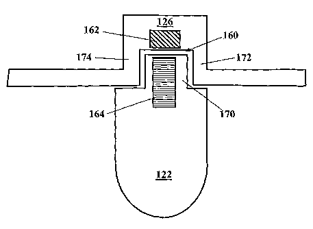
[00017] FIG. 7 is a cross-sectional view of a pad coupler operably
attached to a printing pad illustrating a magnetic interface, in accordance
with
one embodiment of the present invention.
DETAILED DESCRIPTION OF THE PRESENTLY PREFERRED EMBODIMENTS
[00018] FIG.1 is a perspective view of a pad printer in accordance
with one embodiment of the present invention, shown generally by numeral 100.
4
CA 02633821 2010-08-24
Printer 100 includes a frame 110. At least one pad assembly 120 is operably
attached to the frame 110. A cliche plate 112 is operably attached to the
frame
110. Those skilled in the art will recognize that the printer 100 can vary and
is
not limited to the configurations located in the description and illustrations
provided herein.
[00019] In one embodiment, the pad assembly 120 includes a
printing pad 122 that reciprocates into contact with the cliche plate 112 and
an
ink cup 124. Pad assembly 120 further includes a pad coupler 126, which is
operably attached to the print pad 122 and the frame 110. Printing pad 122 is
a
deformable pad onto which ink is transferred, and from which the ink is
transferred to an object to be imprinted. A typical printing pad 122 is formed
from
a resilient, low permeability material such as silicone rubber or the like.
Pad
assembly 120 includes a motor for powering the reciprocation of the printing
pad
122. Cliche plate 112 and ink cup 124 also reciprocate relative to one another
(as indicated by arrows A) to supply ink to the cliche plate 112. Ink cup 124
includes a reservoir body with an open lower end and a doctor blade or knife
ring (not shown) around the open end. The doctor blade is maintained in
intimate contact with the cliche plate 112 to form a seal for retaining the
ink in
the ink cup 124. The blade also serves to scrape the cliche plate 112 surface
to clean off excess ink as the cliche plate 112 is advanced from a loading
position to a transfer position. Substantially, the only ink retained on the
cliche plate 112 is that in the engraved or etched regions in the cliche plate
112 surface that define the print pattern. As such, a relatively "clean" image
is produced on the printed surface.
[00020] In a first embodiment, shown in FIGS. 2 and 3, at least one,
in this case one, locking mechanism 128 secures the printing pad 122 to the
pad
5
CA 02633821 2010-08-24
coupler 126. The locking mechanism is defined herein as one or more objects
that facilitate removable attachment of the printing pad 122 from the pad
coupler
126. The locking mechanism 128 is removably attached (i.e., the locking
mechanism 128 can be removed and reattached from the printer 100).
[000211 In the embodiment, shown in FIG. 2, the locking
mechanism 128 is a locking ring 130. Ring 130 is positioned through an
aperture formed in the printing pad 122 and the pad coupler 126. The
aperture is shaped to correspond to the shape of the ring 130. Ring 130, for
example, can be a C-shaped clip or clip of another shape. Ring 130 provides
an inward spring force for holding the printing pad 122 fast to the pad
coupler
126.
[000221 In the embodiment, shown in FIG. 3, the locking
mechanism 128 is a pin 140. Printing pad 122 includes a flange portion 132,
which is positioned in between flange portions 134, 136 of the pad coupler
126.
Pin 140 is positioned through an aperture formed in the printing pad 122 and
the
pad coupler 126. Specifically, pin 140 is positioned through apertures of the
printing pad 122 flange portion 132 and the pad coupler 126 flange portions
134,
136. Apertures are shaped to correspond to the shape of the pin 140. Pin 140
can be a smooth member (i.e., lacking grooves) or a screw (i.e., with
grooves).
[000231 In a second embodiment, shown in FIGS. 4 and 5, the
printing pad 122 is operably attached to the pad coupler 126 with at least
one, in
this case two, pad interfaces 150. Pad interfaces 150 includes at least one,
in
this case two, surfaces 152 of the printing pad 122 that correspond to at
least
one, in this case two, surfaces 154 of the pad coupler 126. Surfaces 152 of
the
printing pad 122 interlock with the surfaces of the pad coupler.
6
CA 02633821 2010-08-24
[00024] In the embodiment, shown in FIG. 4, the pad interface 150
includes at least one, in this case two, dovetail interfaces 156. Dovetail
interface
156 includes surfaces at acute angles that prevent the printing pad 122 from
removal (i.e., in a direction along arrow A). However, the printing pad 122
can be
removed when necessary (e.g., requires replacement) by sliding the printing
pad
122 in a direction orthogonal to arrow A (i.e., out of the plane of the page
of FIG.
4).
[00025] In the embodiment, shown in FIG. 5, the pad interfaces
150 include at least one, in this case two, flange interfaces 156. Flange
interface
156 includes surfaces at approximately perpendicular angles that prevent the
printing pad 122 from removal (i.e., in a direction along arrow B). However,
the
printing pad 122 can be removed when necessary (e.g., requires replacement)
by sliding the printing pad 122 in a direction orthogonal to arrow B (i.e.,
out of the
plane of the page of FIG. 5).
[00026] In a third embodiment, shown in FIGS. 6 and 7, the printing
pad 122 is operably attached to the pad coupler 126 with at least one, in this
case one, magnetic interface 160. Pad coupler 126 includes a first magnetic
member 162 and the printing pad 122 includes a second magnetic member 164.
The first and second magnetic members 162,164 are magnetically coupled.
[00027] In the embodiment, as shown in FIG. 6, the first magnetic
member 162 of the pad coupler 126 includes a magnet. The second magnetic
member 164 of the printing pad 122 includes a metallic portion manufactured
substantially from, for example, a ferrous material. The metallic portion is a
pin, such
as a screw, bar, and the like, positioned within a flange portion 170 of the
printing
pad 122. Flange portion 170 is positioned in between flange portions 172, 174
of
7
CA 02633821 2010-08-24
the pad coupler 126. The first and second magnetic members 162, 164 are
positioned within molded apertures within the pad coupler 126 and printing pad
122, respectively. Alternatively, the magnet can be positioned within the
printing
pad 122 and the metallic portion positioned within the pad coupler 126. Those
skilled in the art will recognize that the configuration of the first and
second
magnetic members 162,164 may vary from the described embodiment and
corresponding illustrations.
[00028] In the embodiment, as shown in FIG. 7, the first magnetic
member 162 of the pad coupler 126 includes a magnet. The second magnetic
member 164 of the printing pad 122 includes a metallic portion. The metallic
portion
is a foil member positioned adjacent a surface portion 176 of the printing pad
122. The first magnetic member 162 is positioned within molded aperture within
the pad coupler 126. Alternatively, the magnet can be positioned within the
printing pad 122 and the metallic portion 180 positioned adjacent a surface
portion of the pad coupler 126. Those skilled in the art will recognize that
the
configuration of the first and second magnetic members 162, 164 may vary from
the described embodiment and corresponding illustrations.
[00029] One advantage to a printer made in accordance with the
present invention relates to the fact that a worn printing pad can be changed
without the need for removing multiple screws. Furthermore, the changing
process is relatively easy and less time-consuming. Another advantage relates
to the fact that the pad coupler of the present invention allows direct
mounting of
the printing pad to the frame without the need for a base. As such, less part
are
needed which may reduce manufacturing complexity and cost.
8
CA 02633821 2008-06-09
WO 2007/075259 PCT/US2006/045951
[00030] It is important to note that the figures and description
illustrate specific applications and embodiments of the present invention, and
is
not intended to limit the scope of the present disclosure or claims to that
which is
presented therein. While the figures and description present strategies for
mounting a pad to a pad printer, the present invention is not limited to that
format,
and is therefore applicable to other formats. Upon reading the specification
and
reviewing the drawings hereof, it will become immediately obvious to those
skilled in the art that myriad other embodiments of the present invention are
possible, and that such embodiments are contemplated and fall within the scope
of the presently claimed invention.
[00031] While the embodiments of the invention disclosed herein
are presently considered to be preferred, various changes and modifications
can
be made without departing from the spirit and scope of the invention. The
scope
of the invention is indicated in the appended claims, and all changes that
come
within the meaning and range of equivalents are intended to be embraced
therein.
9