Note: Descriptions are shown in the official language in which they were submitted.
CA 02633883 2008-06-09
1 " ROLLER CHAIN AND SPROCKET SYSTEM"
2
3 FIELD OF THE INVENTION
4 Embodiments of the invention relate to chains and sprockets used
for translating a load and, more particularly, to a chain and sprocket for
lifting
6 and lowering a load vertically in a mast of a drilling rig.
7
8 BACKGROUND OF THE INVENTION
9 A multitude of different chain and sprocket drives are known in
many industries for pushing and pulling a load. Many design considerations
must
11 be taken into account depending upon the size of the load to be moved and
the
12 direction in which it is to be moved.
13 Typically, the links of a flexible chain must interlock to achieve
14 vertical translation. One such interlocking hoisting chain design is taught
in US
Patent 1,427,642 to Rickard. In use, the chain length unravels from around the
16 sprocket during rotation, the chain interlocking as it goes from circular
to linear
17 motion. A thrust backer plate is required to ensure engagement between the
18 chain and the sprocket due to side loading on the chain.
19 US Patent 6,224,037 to Novick teaches an interlocking roller chain
driven vertically by two pinions which engage opposing ends of the chain
rollers.
21 The pinions are enclosed between two flange plates. Drive rollers on the
chain
22 engage the pinions therebetween. Applicant believes Novick's device has a
low
23 teeth to pinion diameter ratio and is similarly subject to side loading
which
24 diminishes the efficiency of the vertical translation. Further Applicant
believes
CA 02633883 2008-06-09
1 that a thrust backer plate opposes the pinions to assist in maintaining
2 engagement between the pinions and the chain.
3 In the case of a drilling rig, large loads are lowered by gravity and
4 pulled vertically in and out of a wellbore. Typically, this lifting and
lowering is
accomplished using a cable and pulley drawworks system for a conventional
6 tubular drilling rig or an injector or chain drive for a coiled tubing
drilling rig.
7 US patent 6,336,622 to Eilertsen et al. (Engineering & Drilling
8 Machinery AS (EDM), Stavanger, Norway) teaches a linked rack and pinion
9 system for raising and lowering a load bearing yoke in a derrick. Each of
the
rack links is an H-beam in cross-section having teeth on parallel opposing
11 flanges. The rack links bear against one another in a vertical guideway in
the
12 derrick. An idler wheel is positioned at the bottom of the derrick for
guiding the
13 rack in a "U-shaped" track to a storage guideway. Load is taken up at the
bottom
14 of the derrick. A pinion driving gear powered by a plurality of drive
motors
engages the rack for pushing and pulling the plurality of interlinked racks.
16 Applicant believes that the EDM arrangement is prone to high
17 sliding contact stresses between the gear teeth and the rack teeth. A
pressure
18 angle is substantially a measure of the driving energy which is lost. A
typical
19 industry standard for rack and pinion or sprocket and chain drives is about
20 or
25 for a strong gear. At a pressure angle of 20 , about 77% of the energy is
21 utilized for work and about 22% generates a negative force that acts to
22 constantly drive the teeth of the rack and the pinion gear apart. The
lifting force
23 of the EDM system has about a 20 to 25 pressure angle which generates
24 sliding friction and creates a significant negative force, pushing the
pinion out of
engagement with the rack. Typically pairs of opposing pinions are used in an
2
CA 02633883 2008-06-09
1 attempt to balance the disengaging force, reducing the efficiency of the
system.
2 Applicant notes that a stress analysis of an exemplary EDM gear at a load of
3 41,667 lbs results in a stress of about 35,700 psi per rack and pinion.
4 Conventionally, materials used for gear and pinions are treated to
handle friction and stresses imposed thereon. Such treated materials are not
6 suitable for use in cold climates, such as the Arctic and particularly when
7 subjected to the high stresses imposed by use in a drilling rig. Lubrication
is
8 typically required for prevention of premature wear of the gear tooth
surfaces.
9 Lack of lubrication or use of contaminated oil typically results in
excessive wear.
There is great interest in the oil and gas industry to find a drive
11 mechanism which can be efficiently pushed and pulled, which is capable of
12 handling large loads with lower stress and with minimal thrust side
loading,
13 particularly for vertical lifting and lowering of the load. Further, there
is interest in
14 reducing the weight of the system to assist in meeting transportation
weight
restrictions in the case of a mobile drilling rig. Of particular interest is
the ability
16 to utilize materials that are suitable for cold climates under reduced
stress.
17 Additionally, there is great interest in industries other than oil and
18 gas drilling which require large pushing and pulling forces to handle loads
of a
19 variety of types with reduced stress on the lifting components, reduced
maintenance and improved efficiency.
3
CA 02633883 2008-06-09
1 SUMMARY OF THE INVENTION
2 Embodiments of the invention utilize interconnectable roller chain
3 links for forming an articulated roller chain. Each of the links bears upon
an
4 adjacent link, when aligned linearly, for forming a substantially rigid
pushing
column. The column is engaged at a linear portion thereof by one or more co-
6 operating sprockets having teeth with an involute profile suitable for
driving the
7 roller chain along a column axis. A resulting pressure angle is
substantially zero
8 and therefore substantially all of the driving force of the sprocket is
translated to
9 movement of the roller chain along the column axis substantially without
thrust
side loading. Embodiments of the invention are suitable to efficiently
translate
11 loads and particularly to translate heavy loads vertically.
12 In a broad aspect of the invention, a system for pushing a load
13 comprises: an articulated roller chain having a plurality of pivotally
connected
14 links, each of the plurality of links being caused, when linearly aligned
and
pushed, to bear upon an adjacent link for forming a substantially rigid linear
16 column portion having a column axis; and one or more sprockets having a
17 plurality of teeth formed thereon, the teeth having an involute profile for
engaging
18 the roller chain at the substantially rigid linear column portion thereof,
wherein
19 the involute profile of the sprocket teeth engages the roller chain to
translate
substantially all of a rotational driving energy from the sprocket to the
roller chain
21 along a line of action perpendicular to a tangent to the involute curve,
the line of
22 action being along the column axis for movement of the roller chain along
the
23 column axis.
24 In another broad aspect of the invention, a rig for raising and
lowering a load comprises: a platform; one or more masts supported on the
4
CA 02633883 2008-06-09
1 platform; a U-shaped articulated roller chain for raising and lowering the
load and
2 having a first vertical portion and second vertical portion and a U-shaped
bottom
3 portion, the roller chain being guided for reciprocating motion within the
one or
4 more masts, the roller chain having a plurality of pivotally connected
links, each
of the plurality of links being caused, when vertically aligned and pushed, to
bear
6 upon an adjacent link for forming a substantially rigid vertical lifting and
lowering
7 column portion having a column axis; and one or more sprockets mounted for
8 rotation in the one or more masts, the one or more sprockets having a
plurality
9 of teeth formed thereon, the teeth having an involute profile for rollingly
engaging
the roller chain at the substantially rigid vertical column portion thereof;
wherein
11 the involute profile of the sprocket teeth engages the roller chain to
translate
12 substantially all of a rotational driving energy from the sprocket to the
roller chain
13 along a line of action perpendicular to a tangent to the involute curve,
the line of
14 action being along the column axis for movement of the roller chain along
the
column axis.
5
CA 02633883 2008-06-09
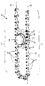
1 BRIEF DESCRIPTION OF THE DRAWINGS
2 Figure 1 is a perspective view of a roller chain and sprocket system
3 according to an embodiment of the invention;
4 Figure 2 is a side view of a sprocket according to an embodiment
of the invention, illustrating an involute profile and a pitch diameter;
6 Figure 3 is a color static nodal stress plot of the sprocket according
7 to Fig, 2 illustrating a stress profile of the sprocket;
8 Figure 4 is a schematic illustrating engagement of the involute
9 teeth of a sprocket with a roller chain according to an embodiment of the
invention;
11 Figure 5 is a perspective view of a roller chain link according to an
12 embodiment of the invention;
13 Figures 6A-6C illustrate a roller chain link according to an
14 embodiment of the invention, more particularly
Fig. 6A is a perspective view of the roller chain link;
16 Fig. 6B is an side view according to Fig. 6A; and
17 Fig. 6C is a sectional view along lines A-A according to Fig.
18 6B;
19 Figures 7A-7D illustrate a roller chain link according to an
embodiment of the invention, more particularly
21 Fig. 7A is a perspective view of the roller chain link;
22 Fig. 7B is a top view according to Fig. 7A;
23 Fig. 7C is a side view according to Fig. 7A; and
24 Fig. 7D is a front view according to Fig. 7A showing a pair of
sprockets engaged therewith;
6
CA 02633883 2008-06-09
1 Figure 8 illustrates a roller chain link according to an embodiment
2 of the invention engaged with a sprocket according to an embodiment of the
3 invention;
4 Figure 9 is a perspective view of a plurality of sprockets according
to Fig. 8 arranged on a shaft for engaging the rollers of a roller chain link
6 according to Fig. 8;
7 Figure 10 is a perspective view of an embodiment of a roller chain
8 link;
9 Figure 11 is a partial perspective view of a drilling rig utilizing a
sprocket and roller chain system according to embodiments of the invention for
11 raising and lowering a dolly in a drilling rig mast;
12 Figure 12 is a front view of a sprocket and roller chain system for
13 use in a drilling embodiment utilizing the roller chain links according to
Fig. 6A-
14 6C and a plurality of sprockets on each of a plurality of shafts driven in
engagement with a roller chain, the mast omitted for clarity;
16 Figure 13 is a perspective view according to Fig. 12;
17 Figure 14 is a partial perspective view of a plurality of sprockets on
18 a plurality of driven shafts according to Fig. 9, driven in engagement with
a roller
19 chain comprising roller chain links according to Fig. 6A-6C in use in a
mast of a
drilling rig;
21 Figure 15 is a partial sectional view of the two sprockets ganged on
22 a shaft, driven in engagement with a roller chain comprising roller chain
links
23 according to an embodiment of the invention for use in a mast of a drilling
rig, a
24 portion of the mast removed for clarity;
7
CA 02633883 2008-06-09
1 Figure 16 is a side view a roller chain and sprocket arrangement
2 for use in a drilling rig according to an embodiment of the invention and
using
3 roller chain links according to Fig. 5 and sprockets according to Figs. 2-4,
the
4 sprockets being sized to engage a first and second linear portion of the
roller
chain;
6 Figure 17 is a perspective view according to Fig. 16 illustrating a
7 roller chain comprising 3-pin links and having follow bearings connected
thereto
8 ofrr engaging a guide in the drilling rig;
9 Figure 18 is a partial perspective view according to Fig. 11 a side
of the mast being made transparent and a portion of the dolly removed to
11 illustrate engagement of the sprockets with a linear portion of the chain;
12 Figure 19 is a partial perspective view of an embodiment of the
13 invention having two parallel spaced masts each having a roller chain
system
14 according to embodiments of the invention guided therein and a truss
extending
between the two masts and supported by the two roller chains for lifting and
16 lowering a load therewith; and
17 Figure 20 is a perspective view of a continuous roller chain
18 comprising links according to Fig. 10 and being driven by a shaft having a
19 plurality of sprockets thereon positioned at a linear section of the
continuous
roller chain.
8
CA 02633883 2008-06-09
1 DETAILED DESCRIPTION OF THE PREFERRED EMBODIMENTS
2 Embodiments of the invention provide a system for pushing and
3 pulling a load. While embodiments of the invention are described herein in
the
4 context of a drilling rig for lifting and lowering tubulars, those of skill
in the art
would appreciate that the system could be utilized to move a load in any
6 direction. Embodiments of the system result in increased efficiencies and an
7 ability to transmit maximum power for moving the load.
8 As shown in Fig. 1, the system 1 generally comprises an
9 articulated roller chain 2 having a plurality of pivotally connected links 3
and one
or more sprockets 4 which engage the roller chain 2 at a linearly arranged
11 portion L thereof. When linearly aligned, the adjacent links 3 in the
roller chain 2
12 are caused to bear upon one another end-to-end for forming a substantially
rigid
13 pushing column portion L of the roller chain 2 which is generally in
compression.
14 The roller chain 2 can also pull loads. The pushing and pulling column
portion L
has a column axis X. The one or more sprockets 4 have a plurality of teeth 5
16 formed thereon, each tooth 5 having an involute curve profile C. The
profiled
17 teeth 5 are received in voids 6 created between two or more rollers 7, in
each of
18 the links 3, for engaging at least one of the two or more rollers 7 for
driving the
19 roller chain 2.
With reference to Figs. 2-4 a pressure angle of substantially zero is
21 created as a result of the involute curve profile C of the teeth 5.
Substantially
22 100% of the rotational energy of the sprocket 4 is transmitted to the
roller chain 2
23 along a line of action A perpendicular to a tangent t to the involute curve
C,
24 which is substantially the column axis X, for moving the roller chain 2
along the
column axis X. Thus, there is little to no resulting negative action or thrust
side
9
CA 02633883 2008-06-09
1 loading and the roller chain 2 remains engaged with the sprocket 4 without
the
2 need for a prior art thrust backing plate or other such arrangement.
3
4 Sprocket
As shown in Figs. 2-4, and in embodiments of the invention, the
6 sprocket teeth 5 have an involute profile which results in a driving force
which is
7 perpendicular to the torque developed by a driven shaft 8 of the sprocket 4
and
8 therefore substantially 100% of the force generated is used for driving the
chain
9 2. Further, as there is little to no radially outward or side loading on the
chain 2,
the sprocket 4 need only engage the chain 2 from one side, eliminating the
need
11 for a backing plate or an opposing driver design such as the opposing
pinion
12 gears used in prior art rack and pinion systems.
13 Prior art chain systems are arranged with chain at least partially
14 wrapped about the sprocket, thus avoiding issues associated with radial
forces.
In embodiments of the present invention, the roller chain is not wrapped about
16 the sprocket and instead, the sprocket engages the chain at a linear
portion of
17 the chain.
18 As is well known by those of skill in the art and as described in
19 Machinery's Handbook 20th ed. Industrial Press Inc. 1976 at page 740, the
shape of the involute curve C is dependent only upon the size of the base
circle.
21 If a first involute, rotating at a uniform rate of motion acts against a
second
22 involute or against a straight line, the first involute will transmit a
uniform angular
23 motion to the second involute or straight line regardless the distance
between
24 the centers of the two base circles. The common tangent of the two base
circles
is both the path of contact and the line of action A.
CA 02633883 2008-06-09
1 In embodiments of the invention, the first involute is a tooth 5 on
2 the sprocket 4 which acts against a straight line, being a pin or roller 7
of the
3 roller chain 2. The straight line is tangent to the involute curve C and is
4 substantially always perpendicular to its line of action A. When the roller
chain 2
is constrained to move substantially in the direction of the line of action A,
the
6 roller chain 2 will be moved at a corresponding and uniform rate to that of
the
7 end of the generating line.
8 Having reference again to Fig. 2, the sprocket's pitch diameter
9 circumference Pd is equal to the lineal displacement of the linear push
chain per
revolution and therefore the sprocket 4 meshes with the rollers 7 on the
roller
11 chain in a linear fashion. The load is perpendicular to the tooth 5 which
is
12 engaged and the torque arm T is % the pitch diameter Pd.
13 As one of skill in the art would appreciate, for large loads such as
14 in a drilling rig, the tooth 5 to sprocket 4 diameter ratio must be
adjusted to be
suitable for the loads contemplated.
16
17 Roller Chain
18 As shown in Figs. 5, 6A-6C, 7A-7D, 8 and 10, the articulated roller
19 chain 2 is formed by the plurality of pivotally interconnected links 3.
Each linearly
extending roller chain link 3 comprises a plurality of transversely extending
pins
21 or rollers 7 supported by one or more frame members 10. Each of the one or
22 more frame members 10 comprises opposing end engagement faces 11,12 for
23 engaging end engagement faces 11,12 on the one or more frame members 10
24 of an adjacent linearly aligned link 3. The engagement faces 11,12 of the
linearly
aligned adjacent links 3 bear upon one another during pushing for stacking and
11
CA 02633883 2008-06-09
1 forming the substantially rigid linear column portion L. The engagement
faces
2 11,12 form stacking surfaces which produce a resisting moment if a link is
3 inclined to leave the linear arrangement.
4 Further, each frame member 10 comprises a tongue member 13
extending outwardly from a first end 14 and a groove member 15 extending
6 outwardly from a second opposing end 16. The tongue member 13 of one link 3
7 is pivotally connected within the groove member 15 of the adjacent link 3
for
8 permitting a pulling action and for articulation of the roller chain 2,
particularly
9 when the links 3 are not linearly aligned. In embodiments of the invention
the
adjacent links 3 are generally pivotally connected using a roller 7.
11 Applicant has contemplated embodiments having three or four or
12 more rollers 7 in each link 3.
13 In embodiments of the invention and best seen in Fig. 6C, each of
14 the rollers 7 is supported for rotation by bearings 20, such as radial
spherical
bearings 20 for rolling engagement with the teeth 5 of the one or more driven
16 sprockets 4, such as shown in Fig. 2. Use of bearings 20 for rotationally
17 supporting the rollers 7 permits the rollers 7 to roll on the surface of
the involute
18 curve C of the teeth 5 of the sprocket 4, thereby reducing any friction
19 therebetween. Typically the bearings 20 are maintenance-free, spherical,
sealed
bearings 20 (GE 35-FW-2RS- available from Schaeffler Canada Inc., Delta, B.C.,
21 Canada).
22
12
CA 02633883 2008-06-09
1 EXAMPLES
2 Roller chain Links
3 As shown in Figs. 5, 6A-6C and 10, the plurality of rollers 7 and the
4 one or more frame members 10 may be arranged to engage the teeth 5 on one
sprocket 4 or on more than one sprocket 4.
6 As shown in Fig. 5, the links 3 comprise two, spaced-apart frame
7 members 10,10 and a plurality of transversely extending rollers 7 connecting
8 therebetween. The rollers 7 in each link 3 are spaced along the frame
members
9 10,10 to form a linear series of voids 6 for receiving teeth 5 of a single
driven
sprocket 4. Each of the frame members 10,10 has a groove member 15 and a
11 tongue member 13 which extending linearly outwardly at opposing ends 14,16
of
12 the frame members 10,10.
13 In the embodiment shown, three pins or rollers 7 are used to create
14 two voids 6 into which the sprocket teeth 5 are received for engagement
with the
rollers 7.
16 Further, in embodiments of the invention, the rollers 7 are
17 supported on bearings 20 fit to the frame member 10 in such a manner that
the
18 sprocket teeth 5 engage the rollers 7 between the bearings 20. In this
19 embodiment, the rollers 7 are subject to shear loading.
As shown in Figs. 6A-6C and 10, the one or more frame members
21 10 and the plurality of rollers 7 are arranged so as to create more than
one
22 parallel, linearly extending series of voids 6 so as to engage a plurality
of parallel
23 or ganged sprockets 4 mounted on a single driven shaft 8.
24 As shown in Figs. 6A-6C, an embodiment of the roller chain link 3
comprises an "E"-shaped frame member 10. A plurality of rollers 7, supported
for
13
CA 02633883 2008-06-09
1 rotation by roller bearings 20, extend perpendicularly outward from a
central
2 member 17 of the frame member 10 and are supported at about a center 18 of
3 the rollers 7 by outer members of the "E"-shaped frame 10. End plates 21
4 support distal ends of the rollers 7 and enclose spaces 23 therebetween for
forming voids 6 through which the sprocket teeth 5 are received and engage the
6 rollers 7. The central member 17 supports a tongue member 13 and a groove
7 member 15 at opposing ends 24,25 of the central member 17 to permit
8 articulated connection between adjacent link members 3. In one embodiment,
9 each roller chain link 3 is therefore capable of engaging four sprockets 4
suitably
spaced axially along a driven shaft 8. In one embodiment, three parallel and
11 spaced sets of rollers 7 are used on each side of the central member 17 for
12 forming two voids 6, thus the link 3 is capable of engaging two adjacent
teeth 5
13 between rollers 7 on each sprocket 4 at the same time. (See Figs. 8 and 9).
The
14 rollers 7 are supported by radial spherical bearings 20 in a roller sleeve
26.
Applicant is aware that in this embodiment, the ganged parallel
16 sprockets 4 on a single driven shaft 8 may be subject to a measure of
winding up
17 which may result in some lack of synchronicity of engagement with the
roller
18 chain 2 between the ganged sprockets 4 mounted thereon.
19 In this embodiment, the rollers 7 are supported in the frame
member 10 and a bearing 20 is supported on the roller 7 between the portions
of
21 the frame member 10. In this embodiment, the sprockets 4 engage the
bearings
22 20 and the rollers 7 are subject to both shear loading and bending loading.
23 Having reference to Fig. 10 and in an embodiment of the invention,
24 the roller chain link 3 comprises two frame members 10,10 spaced apart by a
plurality of rollers 7. Each frame member 10,10 has three inner rollers 7i and
14
CA 02633883 2008-06-09
1 three outer rollers 7o spaced linearly along the frame members 10,10 for
forming
2 linear sets of voids 6 therebetween. An endplate 21 is positioned between
the
3 inner rollers 7i of the two frame members 10,10. Further an endplate 21 is
4 positioned at each outward end 30 of the outer rollers 7o. The inner and
outer
rollers 7i,7o are supported for rotation on a shaft 8 extending through the
frame
6 members 10 and the endplates 21.
7 As in the embodiment described for Fig. 5, each of the frame
8 members 10 has a groove member 15 and a tongue member 13 which
9 extending linearly outwardly at opposing ends 14,16 of the frame member 10.
As shown in Figs. 7A-7D, and in an embodiment of the invention
11 wherein the roller chain 2 is sandwiched between opposing sprockets 4, the
12 roller chain link 3 comprises two C-shaped frame members 40,40, each of the
C-
13 shaped frame members 40,40 supporting a plurality rollers 7 thereon. The C-
14 shaped members 40,40 are supported on opposing sides 41,42 of a central
link
member 43, an axes of the rollers 7 being oriented substantially parallel to
the
16 central member 43. The central link member 43 may be arcuate in shape or
17 have one edge which is arcuate in shape. The C-shaped members 40,40 are
18 mounted to the central member 43 so as to offset the rollers 7 relative to
the
19 central link member 43. The drive sprockets 4 are oriented 90 to the
embodiments of Figs. 6A-6C.
21
22 Roller Chain and Sprocket system
23 As one of skill in the art would appreciate, in designing a roller
24 chain and sprocket system, the diameter of the rollers (P1), under specific
load,
CA 02633883 2008-06-09
1 must have a conservative safety factor which is determined as a function of
the
2 roller material and the diameter of the roller.
3 In an embodiment of the invention, the minimum spacing between
4 rollers in the link is 2 X P1 to provide stability to the system. The tooth
root
thickness on the sprocket teeth is made equal to the diameter of the rollers.
For
6 example in a 12-tooth sprocket for engaging a chain having a 2 X P1 spacing,
7 the pitch circumference is 24 X P1 and two teeth engage two rollers in the
link at
8 any given time during operation. In a 21-tooth sprocket having a pitch
9 circumference of 42 X P1, three teeth engage three rollers at any given time
during operation. Thus, it is apparent that the more teeth there are on the
11 sprocket, the more teeth will engage the roller chain at any given time.
12 To increase the safety factor of the sprocket, the roller spacing may
13 be increased, for example to 2.9 X P1 to accommodate an increase in the
tooth
14 root thickness. Thus, in a 15-tooth sprocket the circumference is 43 X P1
but the
safety factor is doubled compared to using the 2 X P1 spacing example.
16 In embodiments of the sprocket and roller chain system, surface
17 hardening and lubrication are typically not required as there is little to
no friction
18 between the driving surfaces.
19 Softer, low temperature-capable materials, unaffected by ductile
brittle transition temperature and suitable for use in cold climates, are
suitable
21 sprocket materials according to embodiments of the invention. In a stress
22 analysis, loading the sprocket to 175,000 lbs resulted in a stress of
25,000 psi
23 which was lower than the stress (35,700 psi) on the gear wheel of a
conventional
24 rack and pinion system under significantly lower loading (41,667 Ibs).
16
CA 02633883 2008-06-09
1 Drilling Rig
2 Embodiments of the invention are particularly suited for vertical
3 translation of heavy loads, such as tubulars, within one or more masts 100
on a
4 platform 101 of a drilling rig 102.
Best seen in Figs. 11, 15, 18 and 19, and in embodiments of the
6 invention, the roller chain 2 is supported for reciprocating action in a
mast 100 of
7 the drilling rig 102 so as to lift and lower the load. The roller chain 2 is
guided in
8 a U-shape having a first linear vertical portion 103, a second linear,
vertical
9 portion 104 and a U-shaped bottom portion 105. One or more single sprockets
4
or a plurality of ganged sprockets 4 are mounted on one or more driven shafts
8
11 supported in the mast 10 so as to permit the one or more sprockets 4 to
engage
12 the roller chain 2 at at least one of the first or second linear vertical
portions
13 103,104 thereof. The one or more sprockets 4 are spaced above the U-shaped
14 bottom portion 105 so as to ensure the roller chain 2 is meshed with the
one or
more sprockets 4 at the linear portion L of the roller chain 2. The
transmission of
16 substantially 100% of the circular power from the one or more driven
sprockets 4
17 results in vertical motion of the roller chain 2 along the column axis X,
18 substantially without side loading as previously described.
19 Further, with reference to Figs. 12, 14, and 17 and in embodiments
suitable for use in a drilling or service rig 102, the one or more driven
shafts 8
21 are driveably connected to one or more conventional motors 106, such as a
22 hydraulic motor. Dynamic/static braking 107 can be provided on each of the
23 driven shafts 8 to slow and to stop the load. Typically, emergency braking
is also
24 provided to lock the shafts 8 against rotation when stopped.
17
CA 02633883 2008-06-09
1 Typically, having reference to Figs. 13 and 18, guide sections 109
2 are positioned at the U-shaped bottom 105 for supporting the chain 2 through
3 the curve-shaped bottom portion 105. Optionally, follow bearings 110 may
4 extend radially outward from opposing sides of the chain links 3 to co-
operate
with the mast 100 and with the guide sections 109 for guiding the roller chain
2
6 therealong. The follow bearing 110 can extend from the rollers 7.
7 Additionally, guide plates (not shown) may be positioned to oppose
8 the one or more sprockets 4 as a backup to further ensure the roller chain 2
9 does not disengage from the sprockets 4.
As shown in Figs. 12 and 13, an embodiment utilizing a U-shaped
11 roller chain 2 comprises interconnected links 3 according to Figs. 6A-6C
and is
12 supported in the drilling mast 100. Four driven shafts 8, each having four
13 spaced, ganged sprockets 4 supported for rotation thereon, are positioned
in
14 vertical alignment above the bottom 105 of the U-shaped chain 2 and along
the
linear vertical portions 103 of the roller chain 2 for engaging the roller
chain 2 at
16 the first linear portion 103 thereof.
17 Optionally as shown in Fig. 12, at least one additional driven shaft
18 8 having four spaced ganged sprockets 4 supported thereon may be positioned
19 adjacent a top end 115 of the first linear portion 103 of the roller chain
2 for
aiding in lifting the chain 2 in a drilling mast 100.
21 A plurality of sprockets 4 can be splined onto a driven shaft 8 for
22 engagement with the rollers 7 on the roller chain links 3. Fig. 15
illustrates an
23 embodiment of the invention utilizing two sprockets 4 on each of four
driven
24 shafts 8 and a co-operating link 3 design having two parallel series of
vertical
18
CA 02633883 2008-06-09
1 voids 6 formed therein for engaging the two ganged sprockets 4 on each
driven
2 shaft 8.
3 As shown in Figs. 14 and 15, the roller chain links 3 of Figs. 6A-6C
4 are interconnected to form a U-shaped chain 2 guided in the mast 100 of a
drilling rig 102. With reference to Fig. 9, four ganged sprockets 4 can be
6 supported on each driven shaft 8.
7 As shown in Fig, 16, at least a portion of the rollers 7 further
8 comprise follow bearings 110 on opposing sides 11,112 of the roller chain 2
to
9 engage the guide sections 109 adjacent the bottom of the mast 100 for
supporting the bottom 105 of the chain 2 for movement therealong.
11 Typically, as shown in Fig. 15, stabilizing tracks 120 can be
12 employed in the mast 100 to assist in maintaining the links 3 in the
linearly
13 aligned column portion L and for strengthening the column L when aligned
14 vertically.
As shown in Figs. 16 and 17, and in an embodiment of the
16 invention using the roller chain link 3 embodiment shown in Fig. 5, one or
more
17 sprockets 4 are positioned in a vertical array within the mast 100 of the
drilling rig
18 102. The sprockets 4 are positioned along a linear portion L, 103,104 of
the roller
19 chain 2 above the U-shaped bottom 105. Conveniently in this embodiment, due
to the size of the sprocket 4 required to drive the chain 2, the sprocket 4 is
able
21 to engage the roller chain 2 at opposing sides 121,122 and therefore acts
to
22 simultaneously push and pull the roller chain 2 within the mast 100 such as
23 shown in Figs. 11 and 18.
19
CA 02633883 2008-06-09
1 Having reference to Fig. 11, a dolly 130 is operatively connected to
2 embodiments of the sprocket and roller chain system 1 for housing apparatus
3 required for manipulating the load.
4 In an embodiment of the invention, best seen in Fig. 17, follow
bearings 110 extend outwardly from at least one of the rollers 7 on each of
the
6 links 3 along a length of the roller chain 2 for engaging a guide section or
support
7 track 109 for aiding in guiding and stabilizing the chain 2 therealong. The
U-
8 shaped support track 109 is provided at the bottom of vertical tracks for
9 supporting the U-shaped bottom portion 105 of the chain 2 therealong. In
this
embodiment, motors 106 used to drive the shafts 8 for rotation of the
sprockets 4
11 may be hydraulic winch motors. In one embodiment contemplated, Applicant
12 believes that each of two sprockets 4 is capable of lifting 175,000 pound
(175K)
13 making the rig substantially a 350,000 pound (350K) rig.
14 In an embodiment of the invention shown in Fig. 19, two parallel
masts (not shown) are spaced apart for supporting on a drilling rig platform.
16 Each of the masts supports a U-shaped roller chain 2 and one or more
sprockets
17 4 as described in embodiments of the invention. A truss 140 extends between
18 the two masts and is operatively connected at opposing ends 141,142 to the
two
19 U-shaped roller chains 2 for supporting a load therebetween. The load is
operatively connected to the truss 140 for lifting and lowering as the two U-
21 shaped chains 2,2 are synchronously reciprocated in each of the two masts.
22 Utilizing the dual sprocket and roller chain systems 1,1, the drilling rig
102 of this
23 embodiment is capable of lifting loads of about 1,050,000 pounds (1050K).
24
CA 02633883 2008-06-09
1 Continuous roller chain
2 In an embodiment of the invention, the roller chain 2 may be
3 formed into a continuous chain 2. The roller chain 2 may be formed using
links 3
4 according to Fig. 10 or links 3 according to other embodiments of the
invention.
As shown in Fig. 20, one or more sprockets 4 are positioned on a
6 driven shaft 8 so as to engage the rollers 7 of the roller chain 2 at a
linear portion
7 L thereof for driving the chain 2 in a direction which is perpendicular to
the torque
8 developed by the driving shaft 8 of the sprocket 4. The continuous roller
chain 2
9 and sprocket 4 arrangement may be used in a variety of industries where a
continuous chain is desirable.
21