Note: Descriptions are shown in the official language in which they were submitted.
CA 02634109 2008-06-18
1
DESCRIPTION
SHAPE-FORMING SHUTTER APPARATUS AND SHUTTER PIECE
THEREOF
TECFINICAL FIELD
[0001]
The present invention relates to a shape-forming shutter apparatus
for shaping food products such as round rice cakes, buns each with a
lo bean-jam filling and sweet buns, as well as to a shutter piece thereof.
Specifically, the present invention relates to a food shape-forming shutter
apparatus and a shutter piece thereof, which are used for a cutting apparatus
for dividing a continuously-fed bar-shaped food dough into the above food
products, as well as for a sealing apparatus for wrapping a filling with a
sheet crust (a piece of food dough).
BACKGROUND ART
[0002]
There have been various types of apparatus for cutting and shaping
food products as apparatuses for cutting a bar-shaped food dough, for
example. The apparatus for cutting and shaping food products repeatedly
opens and closes a cutting opening part in a center portion surrounded by
shutters multiple times while feeding a bar-shaped food dough in a dual
structure including a filling and a crust to the cutting opening part in the
downward direction, and thereby to cut and shape the food dough multiple
times. As an example, there is a cutting/shaping apparatus provided with
CA 02634109 2008-06-18
2
at least three shutter pieces: each includes a cutting surface and a sliding
surface which are adjacent shaping surfaces; and the sliding surface of each
shutter piece is configured to slide on the cutting surface of its neighboring
(separate) shutter piece. This cutting/shaping apparatus includes: a slide
holding member (connecting member) for maintaining the sliding condition
of the sliding surface of each shutter piece on the cutting surface of its
neighboring shutter piece; and an ascending/descending member having an
entering port which the food dough can enter in the downward direction.
This ascending/descending member is provided to be movable up and
1o down and to include three or more (equal to the number of shutter pieces)
vertical shafts at equal intervals on a predetermined circle on the
ascending/descending member. When each vertical shaft is rotated about
its axis, a corresponding swingable member is configured to swing about
the axis in the horizontal direction. Furthermore, each of the shutter
pieces corresponding to the connecting members is configured to be
supported movably in the longitudinal direction of the corresponding
swingable member. This cutting/shaping apparatus further includes a
rotational operation device for synchronously rotating the vertical shafts
about their own axes for the purpose of synchronously swinging the shutter
pieces in the horizontal direction so as to open and close the cutting
opening part. (See, for example, Japanese Patent No. 3009140: Patent
Document 1.)
[0003]
In addition, cutting apparatuses for shaping a semi-open wrapped
food product include a type of semi-open cutting/shaping apparatus having
an edge part in each of the cutting surfaces, and the crust is thus cut with
CA 02634109 2008-06-18
3
the edge parts before closing the cutting opening part. (See Japanese
Patent No. 301500, for example, which will be hereinafter referred to as
"Patent Document 2.")
[0004]
Furthermore, cutting/shaping apparatuses for forming twisted frills
on the top of a wrapped food product include a type of frilled
cutting/shaping apparatus having a shaping plate on the lower surface of
each of the shutter pieces, and the shaping plates form an almost radiation
pattern when the cutting opening part comes to a closing position.. This
lo cutting/shaping apparatus includes connecting members as the slide
holding members. Each connecting member is locked to a corresponding
shutter piece by use of an eccentric pin in which a portion pivotally
supported by an eccentric pin fitting hole provided to the shutter piece is
eccentric to a portion locked to the connecting member. (See, for example,
Japanese Patent Application, Laid-Open No. 2001-037407: Patent
Document 3.)
[0005]
Moreover, sealing apparatuses for wrapping a filling with a sheet
crust (a piece of food dough) by sealing a peripheral portion of the sheet
crust include a type of apparatus using one of the shutter apparatuses
shown in Patent Documents 1 to 3. (See, for example, Fig. 26 in Japanese
Patent No. 3421658: Patent Document 4.)
[0006]
In the cases of the apparatuses shown in Patent Documents 1, 2 and
4, each shutter piece is provided with a slide holding member for holding
the slide of neighboring shutter pieces. However, these apparatuses have
CA 02634109 2008-06-18
4
a problem that they are incapable of shaping food dough into a stable form
when the abrasion or the like between neighboring shutter pieces forms a
gap between the neighboring shutter pieces to allow a part of the food
dough to go into the gap.
[0007]
The apparatus shown in Patent Document 3 includes the connecting
members each for setting the gap between each two neighboring shutter
pieces at an optimal value which allow no part of food dough to go into the
gap. However, this apparatus has a problem that the handling of the
1o apparatus is troublesome, because the fitting position of the eccentric pin
to
which the connecting member is locked needs to be adjusted, in. a case
where an abrasion between the two neighboring shutter pieces or the like
forms a gap inadequately.
[0008]
The present invention has been made for the purpose of solving the
foregoing problems. An object of the present invention is to provide a
food shape-forming shutter apparatus which requires no gap to be adjusted
between each two neighboring sliding shutter pieces, and which is easier to
handle than any conventional type of food shape-forming shutter apparatus.
DISCLOSURE OF THE INVENTION
[0009]
The present invention has been made with the above-described
existing problems. The present invention is a shape-forming shutter
apparatus including a plurality of shutter pieces, each having an shaping
surface and a sliding surface, which are arranged in a circle with the
CA 02634109 2008-06-18
shaping surface of each shutter piece being slidably in sliding contact with
the sliding surface of the neighboring separate shutter piece, the
shape-forming shutter apparatus being capable of dilating and contracting
an opening part surrounded by the shaping surfaces of the plurality of
5 shutter pieces. The shape-forming shutter apparatus is characterized by
including pressure contact biasing means for always keeping the shaping
surface of each shutter piece and the sliding surface of the neighboring
shutter piece slidably in pressure contact with each other.
[0010]
In addition, the present invention is a shape-forming shutter
apparatus, in which shutter pieces each including an shaping surface on its
side are integrally rotatably attached to a plurality of rotational shafts
rotatably provided at equal intervals in a single circle, in which a front end
portion of each shutter piece is slidably in contact with the shaping surface
of the neighboring shutter piece, and which is capable of dilating and
contracting an opening part surrounded by the shaping surfaces of the
respective shutter pieces. The shape-forming shutter apparatus is
characterized by including pressure contact biasing means for biasing the
front end portion of each shutter piece into pressure contact with the
shaping surface of the neighboring separate shutter piece in order that the
frond end portion of each shutter piece and the shaping surface of the
neighboring shutter piece can be kept slidably in pressure contact with each
other, each shutter piece being able to move in a direction in which the
front end portion of each shutter piece is pressed to the shaping surface of
the neighboring separate shutter piece.
[0011]
CA 02634109 2008-06-18
6
Furthermore, the present invention is any one of the shape-forming
shutter apparatuses, which is characterized in that the pressure contact
biasing means is a ring-shaped elastic member for biasing the shutter pieces
equally, and in that the pressure contact biasing means is stretched around
the shutter pieces.
[0012]
Moreover, the present invention is the foregoing shape-forming
shutter apparatus, which is characterized in that the elastic member is
stretched around the shutter pieces at their ends each being separate away
lo from the other end thereof where the shaping surface of the shutter piece
and the sliding surface of the neighboring shutter piece intersect each other.
[0013]
Additionally, the present invention is the foregoing shape-forming
shutter apparatus, which is characterized in that the pressure contact biasing
means is installed by stretching the pressure contact biasing means around
locking parts each provided in an end of the corresponding shutter piece,
which end is separate away from the other end thereof where the shaping
surface of the shutter piece and the sliding surface of the neighboring
shutter piece intersect each other.
[0014]
In addition, the present invention is the foregoing shape-forming
shutter apparatus, which is characterized in that
each shutter piece is supported by a corresponding one of rotational shafts
arranged at equal intervals on a single circle to be rotatable integrally with
the rotational shaft, and to be movable in a direction orthogonal to an axis
of the rotational shaft. The foregoing shape-forming shutter apparatus is
CA 02634109 2008-06-18
7
also characterized in that the pressure contact biasing means is arranged
between each rotational shaft and a locking part provided to the
corresponding shutter piece.
[0015]
Furthermore, the present invention is a shutter piece which includes
a shaping surface and a sliding surface, and which is used for a shutter
apparatus including multiple shutter pieces arranged in a circle with the
shaping surface of each shutter piece being slidably in sliding contact with
the sliding surface of the neighboring separate shutter piece, the shutter
io apparatus being capable of dilating and contracting an opening part
surrounded by the shaping surfaces respectively of the multiple shutter
pieces. The shutter piece is characterized by including a locking parts for
stretching pressure contact biasing means therearound, the pressure contact
biasing means being that for keeping the shaping surface of each shutter
piece and the sliding surface of the neighboring shutter piece slidably in
pressure contact with each other, and the locking parts each being provided
in an end of the corresponding shutter piece, which end is separate away
from the other end thereof where the shaping surface of the shutter piece
and the sliding surface of the neighboring shutter piece intersect each other.
[0016]
Moreover, the present invention is the foregoing shutter piece which
is characterized by including an oblong hole part slidably only engaging
with a sliding part provided to a rotational shaft for supporting the shutter
piece.
[0017]
Additionally, the present invention is a shutter piece
CA 02634109 2008-06-18
8
including a shaping surface throughout its side, and used for a shutter
apparatus in which shutter pieces are integrally rotatably attached
respectively to multiple rotational shafts rotatably provided at equal
intervals in a single circle with a front end portion of each shutter piece
being slidably in sliding contact with the shaping surface of the
neighboring shutter piece, and the shutter apparatus being capable of
dilating and contracting an opening part surrounded by the shaping surfaces
of the respective shutter pieces. The shutter piece is characterized by
including: an oblong hole allowing each shutter piece to move in a
lo direction orthogonal to an axis of the corresponding one of the rotational
shafts, the oblong hole provided in an engagement part of the shutter piece,
which part engages with the rotational shaft; and a locking part, pressure
contact biasing means being stretched around locking parts, the pressure
contact biasing means being for pressing and biasing an end portion of each
shutter piece to the shaping surface of the neighboring shutter piece in
order that the end portion comes into contact with the shaping surface by
pressure.
[0018]
The present invention causes the shaping surface of each shutter
piece and the sliding surface of the neighboring shutter piece to be always
kept slidably in pressure contact with each other in the shutter apparatus.
As a result, the present invention makes it possible to prevent a fine gap
from occurring between the shaping surface and the sliding surface, and
accordingly to solve the above-described existing problems.
BRIEF DESCRIPTION OF THE DRAWINGS
CA 02634109 2008-06-18
9
[0019]
Fig. 1 is an explanatory front view showing an outline of a food
producing machine including a shutter apparatus according to a first
embodiment of the present invention.
Fig. 2 is an explanatory plan view showing a schematic of a
cutting/shaping apparatus.
Fig. 3 is an explanatory auxiliary plan view showing how a shutter
assembly operates.
Fig. 4 is another explanatory auxiliary plan view showing how the
lo shutter assembly operates.
Fig. 5 is yet another explanatory auxiliary plan view showing how
the shutter assembly operates.
Fig. 6 is still another explanatory auxiliary plan view showing how
the shutter assembly operates.
Figs. 7(a) and 7(b) are explanatory perspective views of schematics
respectively of a shutter piece and swingable member.
Figs. 8(a) and 8(c) are plan views each showing a schematic and
operational process of a food producing machine including a shutter
apparatus according to a second embodiment of the present invention.
Figs. 8(b) and 8(d) are explanatory auxiliary cross-sectional front views
each showing the schematic and operational process of the food producing
machine including the shutter apparatus according to the second
embodiment, which are respectively taken along the VIIIb-VIIIb line of Fig.
8(a) and the VIIId-VIIId line of Fig. 8(c).
Fig. 9 is an explanatory auxiliary cross-sectional perspective view
showing schematics respectively of a shutter piece, swingable member and
CA 02634109 2008-06-18
elastic member, which is taken along the IX-IX line of Fig. 8(a).
Fig. 10(a) is a plan view showing a schematic and operational
process of a food producing machine including a shutter apparatus
according to a third embodiment of the present invention. Fig. 10(b) is an
5 explanatory auxiliary cross-sectional plan view showing the schematic and
operational process of the food producing machine including the shutter
apparatus according to. the third embodiment, which is taken along the
Xb-Xb line of Fig. 10(a).
Fig. 11(a) is another plan view showing the schematic and
lo operational process of the food producing machine including the shutter
apparatus according to the third embodiment of the present invention. Fig.
11(b) is another auxiliary cross-sectional view for explaining an action of
the food producing machine including the shutter apparatus according to
the third embodiment of the present invention, which is taken along the
XIb-XIb line of the Fig. 11(a).
Fig. 12(a) is a plan view showing a schematic and operational
process of a food producing machine including a shutter apparatus
according to a fourth embodiment of the present invention. Fig. 12(b) is
an explanatory auxiliary cross-sectional plan view showing the schematic
2o and operational process of the food producing machine including the
shutter apparatus according to the fourth embodiment, which is taken along
the XIIb-XIIb line of Fig. 12(a).
Fig. 13(a) is another plan view showing the schematic and
operational process of the food producing machine including the shutter
apparatus according to the fourth embodiment of the present invention.
Fig. 13(b) is another auxiliary cross-sectional view for explaining an action
CA 02634109 2008-06-18
11
of the food producing machine including the shutter apparatus according to
the fourth embodiment of the present invention, which is taken along the
XIIIb-XIIIb line of the Fig. 13(a).
Fig. 14 is an explanatory view of another embodiment in which an
elastic member is laid across in a tensioned condition.
BEST MODES FOR CARRYING OUT THE INVENTION
[0020]
Descriptions will be provided for a food producing machine 1
1o including a shutter apparatus according to a first embodiment of the
present
invention by use of the drawings. Fig. 1 is an explanatory plan view
showing a schematic of the food producing machine 1. Fig. 2 is an
explanatory plan view showing a schematic of a cutting/shaping apparatus
5. Figs. 3 to 6 are explanatory auxiliary plan views each showing how a
shutter assembly 7 operates. Fig. 7 is an explanatory perspective view
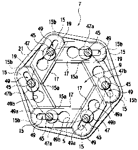
showing schematics respectively of a shutter piece 15 and a swingable
member 47.
[0021]
The food producing machine 1 cuts and shapes multiple times a
two-layered bar-shaped food dough W including a filling W 1 and a crust
W2, and concurrently conveys food products WA in a conveyance direction
(in a leftward direction in Fig. 1). Its base is a box-shaped main body
frame 3. An example of the shutter apparatus, the cutting/shaping
apparatus 5 is provided in the center portion of the main body frame 3.
This cutting/shaping apparatus 5 is designed to repeatedly open and close a
center opening 9 (see Fig. 2) as an opening part of a shutter assembly 7
CA 02634109 2008-06-18
12
multiple times while supplying a bar-shaped food dough W to the center
opening 9 from above, and thereby to cut and shape the bar-shaped food
dough W. A food dough feeding apparatus 11 for feeding the food dough
W to the center opening 9 is provided above the cutting/shaping apparatus
5 in the main body frame 3 (or in an upper section in Fig. 1). A conveyer
13 for conveying the food products WA in the conveyance direction is
provided under the cutting/shaping apparatus 5 in the main body frame 3.
[0022]
Descriptions will be hereinbelow provided chiefly for the
1o cutting/shaping apparatus 5 as an example of the shutter apparatus. As
shown in Figs. 3 to 7, the shutter assembly 7 includes multiple assembled
shutter pieces 15, or six assembled shutter pieces 15 in the present example,
which are arranged in a circle as shown in Fig. 3. As shown in Fig. 7,
each shutter piece 15 has a shaping surface 17 and a sliding surface 19,
which are adjacent cutting surfaces. In this respect, as shown in. Fig. 3,
the shaping surfaces 17 respectively of the six shutter pieces 15 forms an
opening part (or the center opening) 9 surrounded by the shaping surfaces 7
respectively of the shutter pieces 7 so that the opening part can dilate and
contract, or open and close.
[0023]
For example, each shaping surface 17 includes: a vertical part 17a;
a upward slant part 17b, disposed above the vertical part 17a (or upward of
the vertical part 17a in Fig. 7) for pressing the food dough W upward; and a
downward slant part 17c, disposed below the vertical part 17a for pressing
the food dough W downward. The intersection between the shaping
surface 17 and a sliding surface 19 is used as a tip intersection part 15a.
CA 02634109 2008-06-18
13
As an example of locking parts to which an elastic member 21 is locked,
two vertically-arranged locking grooves 15b are provided in an end of the
shaping surface 17, which is different from the end where the tip
intersection part 15a is located. The elastic ember 21 is an example of
pressure contact biasing means (module), which will be described later.
[0024]
Furthermore, each shutter piece 15 has a fitting hole part 49, which
is slidably fitted to a swingable member 47, in the middle of the shutter
piece 15. The swingable member 47 will be described later. The fitting
to hole part 49 includes: an oblong hole part 49a extending in parallel to the
shaping surface 17; and a circular hole part 49b existing at a side of the tip
intersection part 15a of the shutter piece 15. The circular hole part 49b
communicates with the oblong hole part 49a. It should be noted that it
does not matter whether the oblong hole part 49a extends in parallel to the
shaping surface 17. It suffices that the oblong hole part 49a be provided
there so that the swingable member 47 can slide to the oblong hole part
49a.
[0025]
The sliding surface 19 of each shutter piece 15 is configured to slide
on the shaping surface 17 of the neighboring separate shutter piece 15. In
addition, described below is an example of the pressure contact biasing
means for constantly maintaining the contact between the sliding surface
19 of each shutter piece 15 and the shaping surface 17 of the neighboring
shutter piece 15 under a pressure contact condition which enables the
sliding surface 19 to slide on the shaping surface 17. The endless elastic
member 21 such as a rubber-made 0-ring is provided to the shutter pieces
CA 02634109 2008-06-18
14
15 from their outsides so that the elastic member 21 can be stretchingly
wound (around) from one locking groove 15b to another in order that the
elastic member 21 can get the six shutter pieces together, or in order that
the sliding surface 19 of each shutter piece 15 can be biased against the
shaping surface 17 of the neighboring separate shutter piece 15 by
pressuring. It suffices that the elastic member 21 be shaped like an
endless flat belt, and the shape of each locking groove 15b of each shutter
piece 15 may be any shape corresponds to the shape of the elastic inember
21.
1o [0026]
The foregoing configuration biases the sliding surface 19 of each
shutter piece 15 against the shaping surface 17 of the neighboring shutter
piece 15 by pressure contact, and concurrently equally biases the shutter
pieces 15 in a direction in which the opening part 9 is closed. Specifically,
in Fig. 3, the shutter pieces 15 are biased in order that the shutter pieces
15
can rotate clockwise about their own rotational shafts 45. Concurrently,
the shutter pieces 15 are biased in the direction in which the opening part 9
is closed, because the elastic member 21 tends to reduce their diameters
due to its accumulated force.
[0027]
Descriptions will be provided for a configuration which causes the
six shutter pieces 15 to open and close the center opening 9 by seeing Figs.
1 and 2. As described later, a supporting frame 27 is provided to the main
body frame 3 to be movable up and down. As a shutter supporting
member, an ascending/descending case 41 is detachably provided to the
front end portion of the supporting frame 27 (or to the left of the supporting
CA 02634109 2008-06-18
frame 27 in Fig. 2) by, for example, fixing the ascending/descending case
41 to the supporting frame 27 through screwing. This
ascending/descending case 41 includes an entering port into which the food
dough W is capable of going. Six rotatable rotational shafts 45 are
5 provided at equal intervals on a predetermined circle S in the inside of the
ascending/descending case 41.
[0028]
See Fig. 7 once again. A swingable member 47 is eccentrically
provided to each rotational shaft 45. The swingable member 47 is
lo configured to support the corresponding shutter piece 15 so that the
shutter
piece 15 can move in directions indicated by the respective arrows a, or
horizontally in the longitudinal directions of the swingable member 47 (or
in directions orthogonal to the axis of the rotational shaft 45, or in the
same
directions as the swingable member 47 is eccentric to the rotational shaft
15 45), through the fitting hole part 49. In other words, the swingable
member 47 includes a sliding part 47a, an upper restriction part 47b and a
lower restriction part 47c. The sliding part 47a is that on w.hich the
oblong hole part 49a in the fitting hole part 49 slides when the shutter piece
15 swings. The horizontal cross-section of the sliding part 47a is an
ellipse. In addition, the upper restriction part 47b and the lower restriction
part 47c are those for respectively restricting upward and downward
movements of the shutter piece 15 by abutting on the shutter piece 15 while
the shutter piece 15 is swinging. In this respect, "upward" and
"downward" means being oriented upward and downward in the axial
direction of the rotational shaft 45. The diameter of the upper restriction
part 47b is larger than that of the lower restriction part 47c.
CA 02634109 2008-06-18
16
[0029]
Here, descriptions will be provided for how the shutter pieces 15
are attached to the respective swingable members 47. The lower
restriction part 47b of one of the swingable members 47 is positioned to the
circular hole part 49b of the corresponding shutter piece 15. Thereafter,
the shutter piece 15 is raised to a position where the shutter piece 15 abuts
on the upper restriction part 47b of the swingable member 47 (see Fig.
7(a)). Subsequently, the shutter piece 15 is horizontally moved toward the
tip intersection part 15a of the shutter piece 15 to a position where the
lo lower restriction part 47c holds the shutter piece 15 (see Fig. 7(b)). In
this
manner, the six shutter pieces 15 are slidably attached to the respective
swingable members 47. After that, the endless elastic member 21 is
stretchingly wound from one locking groove 15b to another, as the locking
parts of the shutter pieces 15, from outside the shutter pieces 15 in the way
that the elastic member 21 gets the six shutter pieces 15 together, or in the
way that the shaping surface 17 of each shutter piece 15 slidably contacts
the sliding surface 19 of the neighboring shutter piece 15 by pressure.
Thereby, the shutter pieces 15 are attached to the respective swingable
members 47 in the way that each shutter piece 15 abuts on the neighboring
shutter piece 15. As shown in Figs. 3 to 6, each swingable member 47 is
configured to swing about the axis of the corresponding rotational shaft 45
in the horizontal direction when the rotational shaft 45 is rotated about the
axis.
[0030]
When the slide holding member (connecting members) is used as in
the case with the conventional practice, the attaching of a shutter piece
CA 02634109 2008-06-18
17
needs consideration of another shatter piece. For example, the shutter
piece needs to be slit on the neighboring shutter piece to be attached. By
contrast, the present embodiment makes it possible to attach each shutter
piece 15 independently with no consideration paid to any other shutter
piece 15. This makes it easy to attach the shutter pieces 15 to the
respective swingable members 47.
[0031]
See Fig. 2 once again. The cutting/shaping apparatus 5 is provided
with a rotational operation apparatus 51 for synchronously rotating the six
lo rotational shafts 45 backward and forward. In the ascending/descending
case 41, driven gears 53 provided to the respective rotational shafts 45 as
well as a ring-shaped intermediate gear 55 engaging with the driven gears
53 are rotatably provided. In addition, a driving gear 57 is rotatably
provided with engaging with the intermediate gear 55, and the driving gear
57 is provided with a base part for a driven link 59. The driven link 59
and an output shaft 35 of a motor 31 attached to the supporting frame 27
are swingably connected with each other with a connecting link 65 and a
driving link 61. With this connection scheme, the six rotational shafts 45
are rotated by rotating the output shaft 35 of the motor 31 within a required
2o angle range (rightward and leftward). In response to the rotations of the
rotational shafts 45, the shutter pieces 15 swing, respectively. As a result,
the center opening 9 is opened and closed. In other words, the center
opening 9 is dilated and contracted.
[0032]
Descriptions will be provided next for a mechanism for causing the
cutting/shaping apparatus 5 to ascend and descend. A motor 67 is
CA 02634109 2008-06-18
18
provided inside the main body frame 3. The supporting frame 27 is
connected to a horizontal output shaft 69 of the motor 67 with a crank
mechanism 71 interposed in between. Thus, the supporting frame 27 is
provided so as to ascend and descend in response to the rotational drive of
the motor 67, and the cutting/shaping apparatus 5 ascends and descends in
response to the upward and downward movements of the supporting frame
27. The cutting/shaping apparatus 5 ascends while the six shutter pieces
are opened, and the six shutter pieces 15 are being closed while the
cutting/shaping apparatus 5 is descending.
1o [0033]
The conveyer apparatus 13 includes a belt supporting member 77
for supporting a part of a belt 14. The belt supporting member 77 is
ascendably and descendably provided by linking and connecting the belt
supporting member 77 to the other driving shaft 73 of the motor 67 with a
15 cam mechanism 75 interposed in between. In this respect, the elevating of
the belt supporting member 77 prevents the food dough W from dropping
due to its own weight while a cutting/shaping operation is being applied to
the food dough W.
[0034]
Descriptions will be provided for an operation of the embodiment
of the present invention. While the bar-shaped food dough W is being fed
to the center opening (or the opening part) 9 in the downward direction by
the food dough feeding apparatus 11, a rotational drive of the output shaft
35 of the motor 31 in one direction causes the six rotational shafts 45 to
synchronously rotate about their own axis forward (or counterclockwise in
Fig. 3), and thus causes the six shutter pieces 15 to synchronously swing
CA 02634109 2008-06-18
19
horizontally in such a direction as to close the opening part 9. At this time,
each shutter piece 15 is always pressed against one of the two neighboring
shutter pieces 15 (or against a neighboring shutter piece toward which the
shutter piece 15 is capable of horizontally moving in the longitudinal
direction of the swingable member 47) by the biasing force of the endless
elastic member 21 in the way that the shutter piece 15 slides on the
neighboring shutter piece 15.
[0035]
Thereby, the cutting/shaping operation can be applied to the food
1o dough W by pressing it upward with the upward slant part 17b of the
shaping surface 17, and concurrently by pressing it downward with the
downward slant part 17c. At this time, the vertical parts 17a of the
shaping surfaces 17 of the six shutter pieces 15 assemble, and form a
hollow 23 in the center portion on the top surface of the shutter assembly 7.
With this, the center opening 9 ends its first closing operation (see Fig. 5).
Subsequently, the six shutter pieces 15 are further caused to synchronously
swing in such a direction so as to close the center opening 9. Thereby, the
hollow 23 disappears, and the center portion on the top surface of the
shutter assembly 7 becomes flat. With this, the center opening 9 ends its
second closing operation (see Fig. 6).
[0036]
Once the center opening 9 ends its second closing operation, a
rotational drive of the output shaft 35 of the motor 31 in the other direction
causes the six shutter pieces 15 to synchronously swing in such horizontal
direction so as to open the center opening 9. Thereby, the center opening
9 is opened, and thus is returned to its original condition.
CA 02634109 2008-06-18
[0037]
Multiple repetitions of the above-described operation inakes it
possible to apply multiple cutting/shaping operations to the bar-shaped
food dough W, and accordingly to produce multiple food products WA.
5 The multiple food products WA are conveyed to the subsequent process by
the conveyer 13.
[0038]
In this respect, each swingable member 47 supports, through the
fitting hole part 49, the corresponding shutter piece 15 in the way that the
1o shutter piece 15 is capable of horizontally moving in the longitudinal
directions of the swingable member 47. In addition, the endless elastic
member 21 is stretchingly wound around the six shutter pieces 15
constituting the shutter assembly 7 from outside of the shutter pieces 15 to
get the six shutter pieces 15 together, that is, to always keep the
15 neighboring shutter pieces 15 slidably in pressure contact with each other,
thereby causing the shutter pieces 15 to equally dilate and contract the
opening part 9. As a result of the tension of the elastic member 21, the
biasing force works on each shutter piece 15, and the shutter pieces 15 are
thus supported in the way that the sliding surface 19 of each shutter piece
20 15 is always capable of sliding on the shaping surface 17 of the
neighboring separate shutter piece 15 in pressure contact with each other.
[0039]
The above-described embodiment of the present invention enables
the shaping surfaces 17 and the corresponding sliding surfaces 19 to slide
on each other while keeping the shaping surfaces 17 and the sliding
surfaces 19 slidably in pressure contact with each other, even in a case
CA 02634109 2008-06-18
21
where the shutter pieces 15 thermally expand due to their slides or the
shaping surfaces 17 and the sliding surfaces 19 abrade as a result of
repetition of the cutting/shaping process for a long time. For this reason,
unlike the prior art, the embodiment of the present invention makes it
unnecessary to adjust the gap between each two neighboring shutter pieces
15, and accordingly makes it easier to handle the shutter pieces 15.
Furthermore, the embodiment of the present invention makes it possible to
prevent part of the food dough W from going into the gap between each
two neighboring shutter pieces 15, and accordingly to continue a stable
1o production for a long time.
[0040]
Moreover, it suffices that the elastic member 21 be provided so as to
be stretchingly wound around the shutter assembly 7 including three or
more shutter pieces 15 so as to get the entire shutter assembly 7 together.
For this reason, the embodiment of the present invention makes it possible
to reduce the number of component members in comparison with the prior
art, and concurrently makes it easier to process the shutter pieces, as well
as
makes it possible to simplify the configuration of the apparatus.
Consequently, the embodiment of the present invention makes it possible to
2o reduce the processing costs.
[0041]
Descriptions will be provided next for a food producing machine 79
including a shutter apparatus according to a second embodiment of the
present invention by use of Figs. 8 and 9. Fig. 8(a) is an explanatory plan
view showing the schematic and operational process of the food producing
machine 79. Fig. 8(b) is an explanatory auxiliary cross-sectional front
CA 02634109 2008-06-18
22
view of the food producing machine 79 taken along the line VIIIb-VIIIb of
Fig. 8(a). Fig. 8(c) is a plan view showing how the food producing
machine 79 looks when shutter pieces perform a close operation. Fig.
8(d) is an explanatory auxiliary cross-sectional front view of the food
producing machine 79 taken along the line VIIId-VIIId of Fig. 8(c). Fig.
9 is an explanatory auxiliary cross-sectional perspective view showing the
schematics respectively of a shutter piece 15, a swingable member 47 and
an elastic member 81 which are viewed from under, which is taken along
the IX-IX line of Fig. 8. Fig. 9 shows the shutter piece 15 and the like
lo upside down. Incidentally, components which bring about the same
effects as those according to the first embodiment will be denoted by the
same reference numerals, and duplicated descriptions will be omitted.
[0042]
The present embodiment can be used as a shutter apparatus
provided to a sealing apparatus, as shown in Fig. 26 of Patent document 4,
for wrapping a filling with a sheet crust (a piece of food dough) by sealing
a peripheral portion of the sheet crust. In other words, the present
embodiment can be diverted to a shutter apparatus provided to a sealing
apparatus including a mechanism similar to the shutter asseinbly 7
provided to the cutting/shaping apparatus 5. In this case, the shaping
surface 17 of each shutter piece 15 which has been described with regard to
the first embodiment works as an adhering surface for adhering peripheral
portions of the sheet crust to each other by collecting the peripheral
portions, instead of as the cutting surface.
[0043]
The shaping surface 17 of the shutter piece 15 according to the
CA 02634109 2008-06-18
23
second embodiment includes an upper vertical part 17d, a slant part 17e
and a lower vertical part 17f, starting from the top surface. The sliding
surface 19 is formed so as to slidably engage with the shaping surface 17.
[0044]
In addition, an example of the contact pressure biasing means is an
elastic member 81, such as the 0-ring, which is put on all the shutter pieces
and the sliding members 47. The elastic member 81 is put thereon by
being stretchingly wound around locking grooves 83a of locking parts 83
and locking grooves 47e of locking parts 47d provided to lower portions of
lo the swingable members 47, the locking parts 83 each fixedly provided to a
rear end portion of the shutter piece 15 which is located at the other side of
a front end portion of the shutter piece 15 where the shaping surface 17 and
the sliding surface 19 intersect each other. Specifically, each shutter piece
15 is biased in a direction in which the locking part 83 comes closer to the
15 corresponding rotational shaft 45. In other words, each shutter piece 15 is
biased so that the sliding surface 19 of the shutter piece 15 can contact the
shaping surface 17 of the neighboring shutter piece 15 by pressure. As a
result, because the biasing force works on the shutter piece 15 due to the
tension of the elastic member 81, the sliding surface 19 of each shutter
piece 15 and the shaping surface of the neighboring separate shutter piece
15 are always slidably kept in contact with each other by pressure. It
should be noted that it is desirable that the elastic member 81 be an elastic
member configured to have a hook or the like for locking the elastic
member to the locking parts 47d and 83 in one end of the elastic member as
well as an appropriately-shaped locked part in the other end thereof. The
elastic member 81 may be a general coil spring or the like, for example.
CA 02634109 2008-06-18
24
Furthermore, the locking part 83 of the shutter piece 15 may be cut out and
formed integrally with the shutter piece 15.
[0045]
The shutter apparatus is ascendably and descendably provided
above paired pallets 85a and 85b as a molding box. Multiple pairs of
pallets 85a and 85b are provided to an endless chain, which is not
illustrated, at equal intervals, and are intermittently conveyed and
positioned at a lower location of the shutter apparatus. Each paired pallets
85a and 85b include their respective semi-circular concave parts at their
1o parts which are opposite to each other, and have a circular hole 87 in the
joining part. Moreover, an endless belt 89 for supporting the crust W2
from under is provided under each paired pallets 85a and 85b, and is
conveyed and driven in synchronism with the pallets 85a and 85b.
[0046]
Next, descriptions will be provided for a process in which the
shutter assembly 7 seals the crust W2. The crust W2 is placed on the top
surfaces of the pallets 85a and 85b so as to be almost concentric with the
hole 87. A concave portion is formed in the center portion of the crust W2
by an unillustrated pushing member. Subsequently, the filling W 1 is fed
into the concave portion by a filling material feeding apparatus (whose
illustration is omitted). The crust W2 and the filling W 1 thus fed are
conveyed to a lower location of the shutter assembly 7, and are
subsequently halted temporarily. Thereafter, the shutter assembly 7 is
lowered near the pallets 85a and 85b (see Fig. 8(b)). At this time, the
shaping surfaces 17 of the respective shutter pieces 15 push the peripheral
portion of the crust W2 toward the center thereof, and thereby seal the crust
CA 02634109 2008-06-18
W2 so that the filling W 1 is wrapped with the crust W2 (see Figs. 8(c) and
(d)).
[0047]
When, as described above, the shutter pieces 15 swing (rotate)
5 counterclockwise in Fig. 8(a) so as to close the center opening 9, or to
reduce the diameter of the center opening 9, each of sliding surfaces 19 of
each shutter pieces 15 is sliding on each of shaping surfaces 17 of the each
neighboring shutter pieces 15 while each of the sliding surfaces 19 of each
shutter pieces 15 is kept to be pressured against (toward) each of the
1o shaping surfaces 17 of the respective neighboring shutter pieces 15. As a
result, no finest gap occurs between the sliding surface 19 of each shutter
piece 15 and the shaping surface 17 of the neighboring shutter piece 15,
and the above-described exiting problem can be solved.
[0048]
15 Even in a case where the sealing process is repeated for a long time,
unlike the prior art, the foregoing second embodiment makes it unnecessary
to adjust the gap between each two neighboring shutter pieces, and
accordingly makes it easier to handle the shutter pieces 15, as in the first
embodiment. Furthermore, the embodiment of the present invention
20 makes it possible to prevent part of the food dough W from going into the
gap between each two neighboring shutter pieces 15, and accordingly to
continue a stable production for a long time.
[0049]
In the above-described embodiment, the shaping surface 17 of each
25 shutter piece 15 and the sliding surface 19 of the neighboring separate
shutter piece 15 are illustrated as being in full contact with each other.
CA 02634109 2008-06-18
26
Actually, however, the front end portion of each shutter piece 15 where the
sliding surface 19 and the shaping surface 17 intersect each other slidingly
contacts the shaping surface 17 of the neighboring separate shutter piece 15.
In other words, a slight room for escape is formed in the sliding surface 19
of each shutter piece 15. It should be noted that the shutter pieces 15 may
be configured so that the sliding surface 19 of each shutter piece 15 and the
shaping surface of the neighboring separate shutter piece are in full contact
with each other. Whether the sliding surface 19 of each shutter piece 15
and the shaping surface of the neighboring separate shutter piece 15 should
lo be in full contact or in partial contact with each other belongs to the
design
matter.
[0050]
Figs. 10(a) and (b) as well as Figs. 11(a) and (b) show a shutter
apparatus according to a third embodiment of the present invention. This
shutter apparatus is a modification of a shutter apparatus described in
Japanese Examined Patent Application Publication No. Hei. 4-52738.
[0051]
The overall configuration of the shutter apparatus according to the
third embodiment is publicly known as described in the Japanese Examined
Patent Application Publication No. Hei. 4-52738. For this reason,
descriptions will be provided for the schematic thereof. The shutter
apparatus is configured to include a regular polygonal guide hole 103 in a
frame 101. Shutter pieces 107 are provided inside this guiding hole 103
so as to respectively correspond to inner wall parts 105 constituting the
polygon into which the guiding hole 103 is formed. The shutter pieces
107 are capable of sliding along the corresponding inner wall parts 105.
CA 02634109 2008-06-18
27
Each shutter piece 107 is shaped like a trapezoid and its external shape is
similar to that of each shutter piece shown in Japanese Examined Patent
Application Publication No. Hei. 4-5273 8. Specifically, each. shutter
piece 107 includes: an shaping surface 107A; a first sliding surface 107B
slidably contacting the corresponding inner wall part 105 of the guide hole
103; and a second sliding surface 107C slidably contacting the shaping
surface 107A of the neighboring separate shutter piece 107.
[0052]
A movement member (or a movement rod) 109 capable of moving
io in a direction in parallel to a direction in which an appropriate inner
wall
part 105 of the guide hole 103 extends is supported reciprocativelly by the
frame 101 through a bracket 101 B. This movement member 109 and a
shutter piece whose first sliding surface 107B slidably contacts the
appropriate inner wall part 105 are integrally connected to each other by
use of a connecting member 111 such as a rod.
[0053]
The foregoing configuration causes the reciprocating movement of
the movement member 109 in the longitudinal direction to contract and
dilate an opening 113 surrounded by the shaping surfaces 107A. of the
2o respective shutter pieces 107.
[0054]
The foregoing configuration includes pressure contact biasing
means for always keeping the shaping surface 107A of each shutter piece
107 and the second sliding contact surface 107C of the neighboring shutter
piece 107 slidably in pressure contact with each other. Specifically, a
locking groove as a locking part 117 to which an endless elastic nlember
CA 02634109 2008-06-18
28
115 as an example of the pressure contact biasing means is locked (or
around which the endless elastic member 115 is stretchingly wound) is
formed in an end of each shutter piece 107. The end portion is separate
away from the other end of the shutter piece 107 on which end the shaping
surface 107A of the shutter piece 107 and the second sliding contact
surface 107C of the neighboring shutter piece 107 intersect each other.
[0055]
For this reason, the biasing force of the endless elastic member 115
as the pressure contact biasing means in the diameter reducing (or the
io contracting) direction always keeps the shaping surface 107A of each
shutter piece 107 and the second sliding contact surface 107C of the
neighboring separate shutter piece 107 slidably in pressure contact with
each other. As a result, no fine gap occurs between the sliding surface
107A of each shutter piece 107 and the shaping surface 107C. of the
neighboring shutter piece 107, and the above-described exiting problems
can be solved.
[0056]
It goes without saying that the shutter apparatus with the foregoing
configuration can be used as the shutter mechanism for the cutting/shaping
2o apparatus. The shutter apparatus can be also used with the opening 113
being dilated and contracted without closing the opening 113 completely.
In this case, the shutter apparatus is used for gathering, for example,
multiple ball-shaped, cylindrical, or columnar food products, food dough or
the like, which are placed in the opening 113, to the center portion of the
opening 113. For this reason, the shutter apparatus is useful for packing
multiple food products or the like, as an aggregate, in a box.
CA 02634109 2008-06-18
29
[0057]
Figs. 12(a) and (b) as well as Figs. 13(a) and (b) show a shutter
apparatus according to a fourth embodiment of the present invention.
This shutter apparatus is a modification of a shutter apparatus described in
Japanese Patent No. 2729898. Because the overall configuration of the
shutter apparatus is publicly known by the patent, descriptions will be
provided for the schematic of the shutter apparatus.
[0058]
The shutter apparatus includes multiple rotatable rotational shafts
lo 151 which are arranged at equal intervals on a single circle. A guide part
153 in which mutually parallel guide surfaces are formed is formed in each
rotational shaft 151. The guide surfaces are formed by cutting away the
respective parts of the rotational shaft 151 which are opposite to each other.
A shutter piece 155 is attached to each guide part 153 so as to be rotatable
together with the rotational shaft 151, and to be slightly movable in a
direction orthogonal to the axis of the rotational shaft 151.
[0059]
More specifically, each shutter piece 155 is configured to include a
shaping surface 155F around all of its sides. The external shape of each
shutter piece 155 is similar to that of each shutter piece described in
Japanese Patent No. 2729898, and is thus publicly known. For this reason,
detailed descriptions for the external shape will be omitted. An oblong
hole 159 which is fitted to the guide part 153 of the rotational shaft 151 is
formed in a hub 157 of the shutter piece 155 supported by each rotational
shaft 151. This oblong hole 159 is that which is oblong in a longitudinal
direction in which a line joins the center of the shutter piece 155 and a
front
CA 02634109 2008-06-18
end part 161 of the same shutter piece 155. For this reason, the oblong
hole 159 is allowed to slightly move in the longitudinal direction relative to
the rotational shaft 151.
[0060]
5 The front end part 161 of the shutter piece 155 supported by each
rotational shaft 151 slidably contacts the shaping surface 155F of the
neighboring shutter piece. An opening 163 surrounded by the shaping
surfaces 155F of the respective shutter pieces 155 is dilated and contracted
by rotating the rotational shaft 151 forward and backward. In addition,
1o the front end part 161 of each shutter piece 155 and the shaping surface
155F of the neighboring shutter piece 155 are always kept slidably in
pressure contact with each other.
[0061]
Because the shaping surface 155F of each shutter piece 155 is
15 formed throughout the periphery of the shutter piece 155, the shutter piece
155 can be used by rotating the rotational shaft 151 only clockwise in Fig.
12. In a case where, however, the shaping surface 155F of each shutter
piece 155 is not formed throughout the periphery of the shutter piece 155,
the shutter piece 155 is used by rotating the rotational shaft 151 forward
2o and backward. It should be noted that each shutter piece may be used by
rotating the rotational shaft 151 forward and backward even when being
configured to be used by unidirectionally rotating the rotational shaft 151.
[0062]
Specifically, groove-shaped locking parts 167 around which an
25 endless elastic member 165 as an example of the pressure contact biasing
means is stretchingly wound are formed in the hubs 157 of the shutter
CA 02634109 2008-06-18
31
pieces 155, respectively. As a result, the biasing force of the elastic
member 165 causes the front end portion of each shutter piece 155 to abut
on the shaping surface 155F of the neighboring shutter piece 155 by
pressure, and thus keeps the front end portion in pressure contact with the
shaping surface 155F. Accordingly, the front end portion and the shaping
surface 155F slide on each other while the front end portion is kept in
pressure contact with the shaping surface 155F.
[0063]
For this reason, the foregoing configuration causes no fme gap in
1o the contact part between the front end portion of each shutter piece 155
and
the shaping surface 155F of the neighboring shutter piece 155.
Furthermore, even in a case where, as shown in Fig. 13, the front end
portions 161 of the respective shutter pieces 155 gather in the center
portion of the opening, no fine gap occurs among the front end portions
161 of the respective shutter pieces 155, and the above-described exiting
problems can be solved.
[0064]
The present invention should not be limited to the foregoing
embodiments of the present invention and is capable of being carried out as
the following variety of applications.
[0065]
In the first embodiment, the locking grooves 15b to which the
elastic member 21 is locked is provided to an end of each shutter piece 15,
and the elastic member 21 is put on the six shutter pieces 21 to get the six
shutter pieces 21 together by stretchingly winding the elastic member 21
around the shutter pieces 21 from outside. It suffices, however, that the
CA 02634109 2008-06-18
32
biasing force work on the shutter pieces 15 due to the tension of the elastic
member 21 so that each shutter piece 15 slides on the neighboring shutter
piece 15. For this reason, the elastic member may be put on the shutter
pieces by stretchingly winding the elastic member around locking parts,
such as pins, which be instead installed upright in a bottom surface of each
shutter piece 15. Otherwise, the elastic member 21 may be put on the
shutter pieces 15 by stretchingly winding the elastic member 21 around the
locking parts 83, which have described with regard to the second
embodiment. Thereby, each shutter piece 15 and the neighboring shutter
lo piece 15 are always capable of being kept in the slidable condition.
[0066]
Furthermore, as shown in Fig. 14, the elastic member 21 may be put
on each two neighboring shutter pieces 83 so as to be stretchingly wound
(around) between the two neighboring shutter pieces 83. It should be
noted that this configuration is applicable to each of the first, third and
fourth embodiments. In other words, a configuration may be used,
wherein a hook, such as a pin, which serves as a locking part is provided to
an end portion of each shutter piece so that the elastic member is
stretchingly wound between each two neighboring shutter hooks.
[0067]
Although, in the foregoing embodiments, having been described as
being the endless members, the elastic members 21, 81, 115 and 165 do not
have to be endless. For example, a string-shaped elastic member may be
used. In this case, a connecting part (for example, a protruding part) is
provided to an end portion of the elastic member whereas a connected part
(for example, a hole) is provided to the other end portion of the elastic
CA 02634109 2008-06-18
33
member so that the connected part thereof corresponds to the connecting
portion thereof. Subsequently, the elastic member is put on the shutter
pieces to get the shutter piece together by stretching the elastic member
around the shutter pieces, and finally by connecting the connecting part and
the connected part (or the protruding part and the hole) to each other.
Such configuration also causes a biasing force to take place in the elastic
member, and thus makes it possible to cause the biasing force of the elastic
member to work on the shutter pieces in a way that each two neighboring
shutter pieces slide on each other. Furthermore, if multiple h.oles are
lo provided to the former end portion of the string-shaped elastic member, it
is
possible to adjust the biasing force working on the shutter pieces by
changing a hole which is connected to the protruding part for another.
[0068]
Additionally, in the foregoing embodiments, each of the elastic
members 21 and 81 has been described as being all configured of an elastic
material. However, another configuration may be used, wherein a part of
the elastic member includes an elastic material whereas the rest of the
elastic member is configured of, for example, a string or the like which is
made of fibers. It suffices that the elastic member be provided in the way
that each shutter piece can slide on the neighboring shutter piece due to the
biasing force from the means for biasing each two neighboring shutter
pieces to each other when the shutter assembly 7 opens and closes the
center opening 9.
[0069]
Moreover, in the foregoing embodiments, the rotational shaft 45
and the swingable member 47 have been described as being the integrated
CA 02634109 2008-06-18
34
members. However, it suffices that the swingable member 47 swing about
the axis of the rotational shaft 45. For this reason, the rotational shaft 45
and the swingable member 47 may be separately provided and connected to
each other with a screw member or the like through the engagement parts
(for example, concave and convex engagement mechanisms) respectively
provided thereto.
[0070]
In addition, each shaping surface and each sliding surface 19 of
each shutter piece 15 may be formed into various shapes depending on an
lo expected purpose, for example, the shapes shown in Patent Document 2 or
4.
[00711
Furthermore, the bar-shaped food product W continuously fed has
been described as being pushed out of the food dough feeding apparatus 11.
Instead, for example, a bar-shaped food product W, into which a
belt-shaped food dough (for example, bread dough) transferred by the
transfer conveyer is formed by rolling up the end portions thereof, may be
fed to the center opening 9 of the shutter assembly 7 so as to drop down
from a downstream end portion of the transfer conveyer. In addition, the
2o bar-shaped food product W may be cut into cut food products while being
fed to the center opening 9 of the shutter assembly 7. The shutter
assembly 7 is provided between two transfer conveyers consisting of the
original transfer conveyer and the other transfer conveyer newly provided
downstream of the original transfer conveyer in a way that the center
opening 9 is opened and closed in the vertical direction, that is, by
providing the shutter assembly 7 to a shutter supporting member in which
CA 02634109 2008-06-18
the rotational shafts 45 are arranged in the horizontal direction.