Note: Descriptions are shown in the official language in which they were submitted.
CA 02634551 2013-06-04
87782-2
METHODS OF MAKING POLYMERIC ARTICLES AND THE POLYMERIC
ARTICLES FORMED THEREBY
TECHNICAL FIELD
[0001] The present disclosure relates to methods of making polymeric
articles and
the articles made thereby and, in particular, to methods of making polymeric
gel articles
and the articles made thereby.
BACKGROUND
[0003] Many frequently used objects comprise materials that are hard to the
human touch and/or result in friction when disposed against a human body,
especially in
repetitive motions. It is generally thought desirable to make the body
contacting regions
of such objects as soft as possible in order to make their use more
comfortable for a user
e.g., by reducing pressure and/or friction. "Body contacting," as used herein,
means
contacting a user's skin and/or clothing. Many attempts have been made to make
such
objects or the body contacting regions of such objects more comfortable for a
user. For
example, relatively rigid razor and toothbrush handles have been provided with
regions
of softer materials, including disposing the softer regions with "fins," which
bend more
easily at thin gauge. Hairbrushes have been provided with a sheath of
relatively soft
polymeric material disposed about a rigid handle. Luggage, backpack, briefcase
and
purse handles have been provided with relatively thick padded handles.
[0004] A need exists in the art for improved methods of making polymeric
articles.
SUMMARY
[0005] The present disclosure is directed, in one embodiment, to a method
of
molding an article. The method comprises selecting a first mold section
comprising an
upper surface, the upper surface comprising a recessed region, and the
recessed region
CA 02634551 2008-06-20
WO 2007/092091
PCT/US2006/049263
comprising a plurality of mold units disposed therein; disposing a barrier
layer onto the
upper surface of the mold, the barrier layer comprising a thermoplastic
elastomeric
(TPE) material; dispensing a first portion of a polymeric gel precursor onto
the barrier
layer; disposing a stabilizing layer over the polymeric gel precursor and
forming an
interface between the gel precursor and the stabilizing layer; advancing the
interface
while applying pressure to the stabilizing layer adjacent to the interface,
until the gel
precursor is covered by the stabilizing layer; closing the mold; forming a
polymeric gel
from the gel precursor; and removing a sheet comprising a plurality of molded
articles
interconnected by a layer of polymerized gel. The method can comprise
releasing the
molded articles from the sheet. The method also can comprise disposing a
fabric layer
onto the barrier layer before dispensing the first portion of the polymeric
gel precursor.
The method also can comprise disposing a fabric layer onto the first portion
of the gel
precursor before disposing the stabilizing layer; disposing a fabric layer
onto the first
portion of the gel precursor, and disposing a second portion of the gel
precursor onto
the fabric layer. An adhesive material also can be disposed onto the
stabilization layer
and/or the fabric layer. The polymerized layer and the stabilizing layer can
each
comprise an adhesive strength, and the adhesive strength of the stabilizing
layer is less
than the adhesive strength of the polymerized layer. The barrier layer can
comprise a
support layer, and the barrier layer can be disposed on the mold with the
support layer
adjacent to the upper surface of the mold. The barrier layer and/or the
stabilizing layer
can comprise opposing surfaces, and a release agent can be disposed on one or
both of
the opposing surfaces. The release agent can be disposed on a surface of the
barrier
and/or stabilizing layers adjacent to the gel precursor.
[0006] Another embodiment is directed to an article formed by the
foregoing
method(s).
[0007] Another embodiment is directed to a method of using such an
article,
and can comprise manually removing the stabilizing film from the article, and
adhering
the polymeric gel to a surface.
[0008] Another embodiment is directed to a shoe insert. The shoe insert
can
comprise a thermoplastic elastomeric (TPE) barrier layer; a polymerized gel
layer
comprising a hardness ranging from about 30 Shore 000 to about 75 Shore 00;
and a
stabilizing layer disposed adjacent to the polymerized gel layer and opposite
the barrier
layer. The TPE can be selected from the group comprising thermoplastic
polyurethane
2
CA 2639551 2017-03-14
(TPU), silicone, and combinations comprising at least one of the foregoing.
The barrier
layer can comprise a support layer, and the TPE can be disposed on the support
layer,
adjacent to the polymerized gel. A release agent can be disposed between the
polymerized gel and the stabilizing layer. The release agent can be disposed
on a
surface of the stabilizing layer adjacent to the polymerized gel layer. The
polymerized
gel layer can comprise a thermoplastic polyurethane. An active agent can be
disposed
in the barrier layer, and the active agent can be selected from the group
consisting of
silver, tolnaftate, undecenoic acid, allylamines, chlorine, copper, baking
soda, sodium
omadine, zinc omadine, azoles, and combinations comprising at least one of the
foregoing. The polymerized gel can comprise an adhesive strength sufficient to
adhere
to the inner surface of a shoe.
[0009] In another embodiment, the shoe insert comprises a thermoplastic
elastomeric
barrier layer, the barrier layer comprising an active agent; a polymerized gel
layer; and
a stabilizing layer disposed adjacent to the polymerized gel layer and
opposite the
barrier layer. The active agent can be selected from the group consisting of
silver,
tolnaftate, undecenoic acid, allylamines, chlorine, copper, baking soda,
sodium
omadine, zinc omadine, azoles, and combinations comprising at least one of the
foregoing. The TPE can be selected from the group comprising thermoplastic
polyurethane (TPU), silicone, and combinations comprising at least one of the
foregoing. The barrier layer can comprise a support layer, and the TPE can be
disposed
on the support layer, adjacent to the polymerized gel. The polymerized gel
layer can
comprise a hardness ranging from about 30 Shore 000 to about 75 Shore 00. A
release
agent can be disposed between the polymerized gel and the stabilizing layer.
The
release agent can be disposed on a surface of the stabilizing layer adjacent
to the
polymerized gel layer. The polymerized gel layer can comprise thermoplastic
polyurethane. The polymerized gel can comprise an adhesive strength sufficient
to
adhere to the inner surface of a shoe.
In another embodiment, the molded article comprises a thermoplastic
elastomeric
(TPE) barrier layer; a polymeric material layer disposed adjacent to the TPE
barrier
layer; and a stabilization layer disposed adjacent to the polymeric material
layer,
opposite the TPE barrier layer.
[0010] The above described and other features are exemplified by the following
figures and detailed description.
DRA WINGS
[0011] Referring now to the figures, which are exemplary embodiments, and
wherein
like elements are numbered alike:
3
CA 02634551 2013-06-04
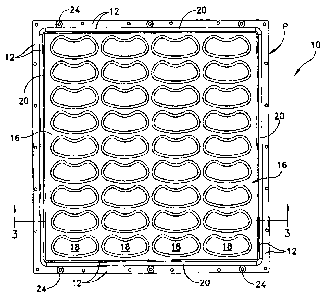
87782-2
[0012] FIG. 1 is a perspective view an exemplary mold that can be used in the
method
according to the present disclosure;
[0013] FIG. 2 is an enlarged perspective view of a portion of the mold shown
in FIG. 1;
[0014] FIG. 3 is a cross-sectional schematic view of the mold shown in FIG. 1,
through
line 3-3;
[0015] FIG. 4 shows the application of a barrier layer to the mold shown in
FIG. 3;
[0016] FIG. 5 shows the application of a gel precursor to the barrier layer
shown in FIG.
4;
[0017] FIG. 6 shows the application of a stabilization layer to the gel
precursor shown in
FIG. 5;
[0018] FIG. 7 shows the method of advancing the stabilization layer over the
gel
precursor shown in FIGS. 5 and 6;
[0019] FIG. 8 shows the stabilization layer covering the gel precursor;
[0020] FIG. 9 shows the mold being closed;
[0021] FIG. 10 shows the mold after closure and the polymerization of the gel
precursor;
[0022] FIG. 11 shows a sheet of material containing molded units, after
removal from the
mold;
[0023] FIG. 12 is a top view of an exemplary shoe heel insert;
[0024] FIG. 13 is a cross-sectional view of the insert of FIG. 12, through
lines 13-13;
[0025] FIG. 14 is a cross-sectional view of the insert of FIG. 12, through
lines 13-13,
showing release of a stabilizing layer from an adhesive layer;
[0026] FIG. 15 is a top view of an exemplary rigid toothbrush handle with a
polymeric
gel handle insert according to the present disclosure, and showing text in
phantom;
[0027] FIG. 16 is a cross-sectional view of the handle insert of FIG. 15;
[0028] FIG. 17 is a cross-sectional view of the handle insert of FIG. 15,
showing release
of the stabilizing layer from the polymeric gel;
4
CA 02634551 2016-01-29
[0029] Figure 18 is a cross-sectional view of the rigid toothbrush
handle, through lines 18-
18, showing the polymeric gel insert adhered in a recess in the rigid handle;
[0030] Figure 19 is a cross-sectional view of an alternative
toothbrush handle insert
comprising a flange;
[0031] Figure 20 is a cross-sectional view of the rigid toothbrush handle
shown in Figure 15,
showing the flange of the polymeric gel insert disposed in a recess in the
rigid handle.
DETAILED DESCRIPTION
[0032] The present disclosure is directed to methods of making
polymeric articles and the
articles made thereby, particularly methods of making relatively low durometer
polymeric articles.
Relatively low durometer polymeric materials can be extremely tacky, making
them difficult or
impossible to use in commercial processing techniques such as injection
molding, because the
materials will adhere to the molds. in addition, such materials can comprise
relatively low durability
in comparison to other materials, including other polymeric materials. Thus,
applications for
relatively low durometer polymeric gel materials have been limited, despite
their advantageous
pliability and softness characteristics.
[0033] Figures 1 - 11, when taken together, illustrate an exemplary
method for forming
polymeric gel articles. The present method involves selecting a suitable mold
10 for the desired
product, as shown in Figures 1-3, which can comprise opposing upper and lower
surfaces 12, 14. As
shown, mold 10 can comprise a recessed region 16 defined in the upper surface
12 of the mold,
which is recessed from the upper surface 12 by a depth "D1". It should be
understood that the terms
"bottom" and "top,"" and/or "upper" and "lower" are used herein, unless
otherwise noted, merely
for convenience of description, and are not limited to any one position or
spatial orientation. Also, it
should be understood that the terms "first," "second,'' and the like, herein
do not denote any order,
quantity, or importance, but rather are used to distinguish one element from
another, and the terms
"a" and "an" herein do not denote a limitation of quantity, but rather denote
the presence of at least
one of the referenced item. Further, unless defined otherwise, technical and
scientific terms used
herein have
5
CA 02634551 2013-06-04
87782-2
the same meaning as is commonly understood by one of skill in the art to which
this
disclosure belongs.
[0034] The present mold 10 comprises thirty-six (36) individual mold units 18
defined in
the recessed region 16, each of which corresponds to the shape and size of the
desired
final molded product, which in this instance is a shoe heel insert. Although
illustrated
herein as a shoe heel insert for the sake of convenience, it should be
understood that a
variety of products can be molded using the present method. Each of the thirty-
six (36)
individual mold units 18 is recessed from the upper surface 12 by a depth
"D2", which
corresponds to the desired thickness of the final molded product.
[0035] Mold 10 also can comprise a gasket recess 21 disposed between the
recessed
region 16 and the perimeter "P' of the mold 10, in which a gasket 20 can be
disposed.
Alternatively, gasket 20 can be disposed directly on the upper surface 12 of
the mold 10.
Gasket 20 can provide a seal sufficient to restrict the flow of polymer from
the mold 10.
Gasket 20 or mold 10 can comprise periodic openings to allow entrapped air to
flow out
of the mold 10 during the molding process. For example, as shown, gasket 20
can
comprise openings. Optionally, the mold 10 can comprise one or more
registration guides
24.
[0036] As shown in FIG. 4, after selection of a suitable mold 10, the method
can
comprise disposing a barrier layer 26 onto the mold 10. The barrier layer 26
can be
disposed onto the mold 10 as a sheet of material, or as a coating applied
directly onto the
mold. When applied as a sheet 26, then barrier layer 26 can be applied onto
the mold and
in physical contact with the gasket 20. When applied as a sheet, then the
barrier layer 26
also can comprise registration guides (not illustrated) corresponding to the
registration
guides 24 in the mold 10, in order to aid in its alignment to the mold 10 and
to subsequent
layers. If the barrier layer 26 is not disposed as a sheet, then it can be
disposed directly
onto the upper surface 12 of mold 10. If desired, a release coating may be
used to assist in
releasing the barrier layer 12 from the upper surface 12 of mold 10.
[0037] As shown in FIG. 5, after disposing the barrier layer 26 onto the upper
surface 12
of the mold 10, a gel precursor 28 can be dispensed onto the barrier layer 26.
The gel
precursor 28 can be disposed onto the barrier layer 26 using a variety of
techniques such
as, but not limited to, pouring, injecting, and/or the like.
6
CA 02634551 2013-06-04
87782-2
[0038] Dispensing the gel precursor 28 can comprise pouring a sufficient
amount of the
gel precursor to fill each of the thirty-six (36) individual mold units 18,
rather than filling
a single mold unit 18, as in other processes such as injection molding. For
example, other
methods, such as injection molding, may involve dispensing the gel precursor
28
separately to each mold unit 18. Therefore, using the present mold, thirty-six
(36)
separate dispensing steps would be required. In contrast, the present method
can comprise
dispensing the gel precursor 28 only once onto the barrier layer 26, and the
single
dispensation of gel precursor 28 can provide a sufficient amount of gel
precursor 28 to
form all of the mold units 18 in a single molding cycle. Dispensing the gel
precursor 28
in bulk, rather than separately, can substantially reduce the manufacturing
time of the
present method in comparison to other methods.
[0039] As shown in FIG. 6, after dispensing the gel precursor 28 onto the
barrier layer
26, a stabilizing layer 30 can be disposed over the gel precursor 28, for
example, as a
sheet. If mold 10 comprises registration guides 24, then the stabilizing layer
30 also can
comprise corresponding registration guides (not illustrated) to aid in its
alignment to the
mold 10 and to any subsequent layers. Disposing the stabilizing layer 30 onto
the gel
precursor can comprise disposing a portion of the stabilizing layer 30 onto a
portion of
the gel precursor 28 such that an interface 32 exists between the gel
precursor 28 and the
stabilizing layer 30. Disposing the stabilizing layer 30 onto the gel
precursor 28 can be
performed manually, with a tool such as a roller, as shown in FIG. 7, or the
process can
be automated. The remaining portion of the stabilizing layer 30 can be
advanced onto the
remaining portion of the gel precursor 28 by applying pressure to the
stabilizing layer 30
behind the interface 32, and advancing the interface 32 until the stabilizing
layer 30
covers the entire gel precursor 28, as shown in FIG. 8. The application of
pressure while
advancing the stabilizing layer 30 substantially minimizes the formation of
air bubbles
between the gel precursor 28 and the stabilizing layer 30.
[0040] As shown in FIG. 9, the mold 10 can be closed, for example by disposing
a mold
cover 10a over the stabilizing layer 30. When the mold 10 is closed, the gel
precursor 28
can flow into all regions of the mold 10 defined by the gasket 20, and any
entrapped air
can flow out of the mold through gasket openings 21.
[0041] As shown in FIG. 10, the gel precursor 28 can be allowed to form a
polymerized
gel 29 in the closed mold 10 for a predetermined period of time (e.g., 30
7
CA 02634551 2014-05-15
seconds to 5 minutes). If desired, pressure and/or a vacuum can be applied to
the mold for
various reasons e.g., to increase the speed of processing, to improve the
quality of the
final material, to change the surface characteristics of the polymerized gel,
and/or the
like. As a result, the overall processing time for producing a plurality of
molded products
can be substantially reduced in comparison to other methods such as injection
molding.
In addition, because the time used to dispense the gel precursor 28 is reduced
in
comparison to other methods, it is possible to increase the speed of curing by
varying a
number of factors such as, for example, pressure, temperature, catalyst
concentration
(when used), and/or the like. The use of pressure and/or vacuum during the
molding
process can be desirable when the articles to be formed require more
definition such as
undercuts, and the like. When vacuum forming or thermoforming, it can be
desirable to
utilize molds formed at least in part from a porous composite material, which
allows the
formation of intricate details and surface patterns in the molded article, and
eliminates the
necessity for vent holes in the mold. One example of such a porous composite
material is
breathable aluminum, which is available commercially under the brand name
METAPORTm.
[0042] After curing, the mold 10 can be opened, and a sheet 320 comprising the
molded
products can be removed from the mold 10, as shown in FIG. 11. The presence of
the
barrier layer 26 and the stabilization layer 30 can facilitate the handling of
the sheet 320
because the polymerized gel 29 is encapsulated by the layers 26, 30, which can
be
advantageous when the polymerized gel 29 has adhesive properties that would
otherwise
cause it to adhere to surfaces such as the mold surface, a user's hand, and
the like. The
sheet 320 comprises a plurality of relatively thin regions 29a of the
polymerized gel 29
disposed between the barrier layer 26 and the stabilization layer 30, and
interconnecting
the molded products. The regions 29a of polymerized gel can comprise a
thickness "T1"
corresponding to the depth DI of the recessed region 16 of mold 10. In order
to minimize
waste, the depth DI of the recessed region 16 can be selected to be as small
as possible
while still allowing unrestricted flow of the gel precursor 28 into the region
defined by
the gasket 22. Thus, the depth Di and thickness "T1" of can be varied.
[0043] The molded products can be separated from the sheet 320 and from each
other by
cutting (e.g., die cutting, and the like) through the barrier layer 26,
polymerized gel
regions 29a and stabilization layer 30. The molded products can be
8
CA 02634551 2013-06-04
87782-2
die cut between the polymerized gel regions 29 and 29a and/or through the
polymerized
gel region 29. When the polymerized gel 29 has adhesive properties, then it
may be
desirable to die cut through a portion of the polymerized gel regions 29
adjacent to the
polymerized gel region 29a, such that the sides of the molded units comprise
an exposed
region of polymerized gel. During die cutting, the presence of the
stabilization layer 30
prevents or minimizes the polymerized gel 29 and barrier layer 26 from
shrinking,
thereby substantially maintaining the dimensions of the molded products in
comparison
to the dimension of the mold units 18. Because shrinkage of the molded
products can be
minimized, it may not be necessary to factor shrinkage into the design of the
molds, as
may be necessary with other methods.
[0044] Optionally, a layer 34 can be disposed between any of the foregoing
layers e.g.,
between the stabilization layer 30 and the polymerized gel 29 and/or between
the
polymerized gel 29 and the barrier layer 26. Also optionally, the layer 34 can
be disposed
in the polymeric gel 29 e.g., by disposing a first portion of the gel
precursor 28 onto the
barrier layer 26, disposing the layer 34 over the first portion of the gel
precursor 28, and
disposing a second portion of gel precursor 28 over the layer 34. Layer 34 can
comprise a
variety of materials including, but not limited to, paper, fabric, plastic
film, and/or the
like, as well as composites and/or combinations comprising at least one of the
foregoing.
Layer 34 also can comprise color, graphics and/or indicia, including text.
When layer 34
comprises a fabric layer, the fabric can be knit, woven, non-woven, synthetic,
non-
synthetic, and combinations comprising at least one of the foregoing.
Disposing a fabric
layer as layer 34 can be advantageous because it can trap and disperse air
bubbles that
may otherwise form in or between the layers, resulting in a better appearance
for the final
molded products. Also, the color, design and/or indicia disposed on layer 34
can be
transmitted through other layers when they are formed from colorless and/or
transparent
materials, which can be desirable for aesthetic purposes, as best shown in
FIG. 15.
[0045] Also optionally, layer 34 can be used in place of the stabilization
layer 30. If layer
34 replaces the stabilization layer 30, then it can be applied in the same
manner described
above with respect to the stabilization layer 30.
[0046] In some instances, it may be desirable to be able to adhere the molded
products to
various surfaces. Therefore, optionally, an adhesive (not illustrated) may be
disposed on
one or more surfaces of the final molded products. Also
9
CA 02634551 2013-06-04
87782-2
optionally, an adhesive can be disposed and/or on one or more surfaces of
layers 26, 28,
30 and 34. For example, with reference to FIG. 17, an adhesive can be disposed
on
surface 30b, and the adhesive can be supported by a release and/or support
layer (not
illustrated). Some possible adhesives can comprise pressure sensitive
adhesives,
thermoplastic adhesives, and the like, as well as combinations comprising at
least one of
the foregoing. One example of such a material is available from 3M as product
number
7026.
[0047] In some instances, the polymerized gel 29 may comprise sufficient
adhesive
strength to be adhered to a surface in the absence of a separate adhesive. In
such
instances, it may be desirable that the stabilizing layer 30 can be capable of
manual
release from the polymerized gel 29. Therefore, optionally, the stabilizing
layer 30 can
comprise a release coating (not illustrated) such as silicone, disposed on
surface 30a,
which can assist in the manual release of the stabilizing layer 30 from the
polymerized
gel 29.
[0048] A variety of materials can be used in the foregoing methods to make the
foregoing
polymerized gel 29. The barrier layer 26 can comprise any material capable of
providing
sufficient elasticity to prevent tearing and/or stretching when a force is
applied thereto;
sufficient structural integrity to be formed into predetermined shapes; and
that is capable
of withstanding the environment in which it is intended to be used, without
substantial
degradation. The barrier layer 26 also can be selected to facilitate the
handling of the
polymerized gel layer, which can comprise adhesive characteristics in some
instances.
Therefore, after molding, the barrier layer 26 can be selected to comprise a
relatively
non-tacky surface and a relatively smooth feel to the human touch. Some
possible
materials for the barrier layer 26 include polyolefins, polystyrenes, PVC,
latex rubber,
and thermoplastic elastomers (IPEs), and/or the like, and combinations
comprising at
least one of the foregoing materials. Some possible TPE materials include
polyurethane,
silicone, and/or the like, and combinations comprising at least one of the
foregoing
materials. The barrier layer 26 can comprise an elongation of about 100
percent (%) to
about 1500%, more particularly about 200% to about 1000%, and more
particularly still
about 300% to about 700%'. It should be understood that the modifier "about"
used in
connection with a quantity is inclusive of the stated value and has the
meaning dictated
by the context (e.g., includes the degree of error associated with measurement
of the
particular quantity).
CA 02634551 2008-06-20
WO 2007/092091
PCT/US2006/049263
[0049] Barrier layer 26 can comprise any thickness. For practical
purposes it
has been found that thinner layers can provide improved hand-feel, while
thicker layers
can provide increased durability. Therefore, it is desirable to use the
thinnest barrier
layer possible in order to prevent punctures in the barrier layer 26. When the
polymerized layer 29 is tacky, puncturing the barrier layer 26 can expose the
underlying tacky material of the polymerized gel 29, making it difficult to
handle.
Barrier layer 26 can comprise a thickness ranging from about 0.2 milli-inch
(hereinafter
"mil") to about 5 mil, more particularly from about 0.5 mil to about 3 mil,
and more
particularly still from about 0.6 mil to about 2 mil.
[0050] As noted above, barrier layer 26 can be applied as a sheet of
material
during the molding process. In the form of a sheet, and especially when the
barrier
layer is relatively thin, the barrier material can be very flexible and may
wrinkle and/or
fold very easily during handling, which is not desirable. Therefore, the
barrier layer 26
also can comprise a support layer (not illustrated), which assists in handling
the
material. If the barrier layer 26 comprises such a supporting layer, then the
supporting
layer can be disposed adjacent to the upper surface 12 of the mold 10, with
the barrier
layer material facing away from the upper surface 12, which can be removed
prior to
die cutting, if desired or necessary.
[0051] Also as noted above, if barrier layer 26 is not applied as a
sheet, then it
can be applied as a coating of material during or after the molding process.
If applied
after the molding process, then the barrier layer can be disposed onto the
polymeric gel
28 after formation of the molded units 18, for example by painting, spraying,
brushing
manually, and/or the like. When the barrier layer 26 is not disposed as a
sheet or is not
disposed as a coating during the molding process, then the gel precursor 28
can be
disposed directly onto the upper surface 12 of mold 10, which may require the
use of a
release agent on the upper surface 12.
[0052] The polymerized gel 29,29a can comprise any polymeric material
comprising sufficient structural integrity to be formed into predetermined
shapes,
including foam polymeric materials; sufficient softness and/or pliability to
provide
comfort against a body; and that is capable of withstanding the environment in
which it
is intended to be used, without substantial degradation. The polymeric
material can
comprise a thermosetting polymeric material, an elastomeric polymeric
material,
athermoplastic material, including a thermoplastic elastomeric material, and
11
CA 02634551 2013-06-04
87782-2
combinations comprising at least one of the foregoing. Some possible materials
for the
polymerized gel 29, 29a comprise polyurethane, silicone, and/or the like, and
combinations comprising at least one of the foregoing materials.
[0053] Formation of the gel precursor 28 can take place by a variety of
methods
known to those of skill in the art. For example, formation of a polyurethane
gel can
comprise reacting suitable pre-polymeric precursor materials e.g., reacting a
polyol and
an isocyanate in the presence of a catalyst. In some embodiments, the
polymerized gel
29, 29a can comprise sufficient adhesive strength to adhere to a selected
surface (such as
the inner surface of a shoe). It is possible to vary the adhesive strength of
the polymerized
gel 29,29a by varying, for example, the durometer of the material used to form
the layer.
In addition, the durometer of the polymerized gel 29, 29a can be selected to
provide
articles and/or regions of articles with a predetermined hardness, which can
be tailored
for specific cushioning and/or wear resistance applications.
[0054] The polymerized gel 29, 29a can comprise a durometer ranging from
about 0.01 Shore 00 to less than or equal to about 70 Shore A, more
particularly less than
70 Shore 00, more particularly still less than 60 Shore 00. In some instances,
it may be
desirable that the polymerized gel 29, 29a have adhesive characteristics in
order to
eliminate the use of a separate adhesive to adhere molded units 29 to a
desired surface. In
such instances, the polymerized gel can comprise a durometer of about 30 Shore
000 to
about 85 Shore 00. Polymeric gel materials in such relatively low durometer
ranges can
comprise a jelly-like consistency. One possible material having such adhesive
characteristics is a polyurethane gel comprising a durometer in the range of
about 70
Shore 00 to about 85 Shore 00, which can provide sufficient adhesive strength
to adhere
to a desired surface, such as the surface of an inner shoe, or a rigid plastic
such a
polypropylene. The polymeric gel 29 and/or the barrier layer 26 can comprise
one or
more additives such as, but not limited to, modifiers, coloring agents,
stabilizers, phase
changing materials, ultraviolet inhibitors, and/or active agents as well as
combinations
comprising at least one of the foregoing. The concentration of the additive
can be varied
depending on the desired effectiveness of the agent.
[0055] One possible phase changing materials can comprise phase changing
microspheres (available under the product name Outlast TM), which contain
materials that
can change phases at near body temperature. As a result, heat energy can be
stored in the
barrier layer, resulting in a product that can feel cool or warm.
12
CA 02634551 2013-06-04
87782-2
[0056] Suitable active agents can comprise tolnaftate, undecenoic acid,
allylamines,
chlorine, copper, baking soda, sodium omadine, zinc omadine, azoles, silver,
and/or the
like, and combinations comprising at least one of the foregoing. For example,
silver can
provide an antifungal/antibacterial effect. For purposes of economy and
effectiveness, it
has been found advantageous to include active agents, when used, in the
barrier layer 26.
Because the barrier layer 26 is relatively thin in comparison to the polymeric
gel 29,
disposing such agents in the barrier layer 26 allows the use of reduced total
amounts of
the agents to achieve similar effective concentrations in comparison to
thicker layers,
thereby reducing costs associated with the additives. Also, disposing such
agents in the
barrier layer 26 ensures that the agents are disposed in the outermost layer
of the article
i.e., the body contacting regions, rather than in regions remote from the
user, which can
increase the effectiveness of the agents.
[0057] In some instances, it may be desirable to use colorless materials for
each of the
barrier, polymerized gel and stabilization layers, which can be desirable for
aesthetic
reasons. For example, it can be desirable to use colorless shoe inserts,
particularly in
women's shoes, which are sometimes open-toed, or open-heeled.
[0058] The stabilizing layer 30 can comprise a material that is capable of
substantially
minimizing shrinkage of the barrier layer 26, gel precursor 28 and/or the
polymerized gel
29 during and after processing; providing support for the polymerized gel 29:
and that is
capable of facilitating handling of the polymerized gel 29 and the barrier
layer 26. The
stabilizing layer 30 can comprise any material that is substantially inelastic
in comparison
to the polymerized gel 29, in order to be capable of providing dimensional
stability to the
sheet 320 and/or to the molded products during and after processing. Some
possible
materials for the stabilizing layer 30 include, but are not limited to,
fabrics, paper, plastic
(e.g., polyester, polyethylene, polyvinyl chloride (PVC), and the like) metal,
metallized
plastic, and/or the like, and combinations comprising at least one of the
foregoing
materials. One possible material is oriented polyester film, which is
commercially
available from a variety of sources and a under variety of different product
names (e.g.,
MylarTm). Stabilization layer 30 can comprise a thickness ranging from about
0.2 mil to
about 10 mil, more particularly from about 0.5 mil to about 5 mil, and more
particularly
still from about 1 mil to about 2 mil.
[0059] The foregoing methods and materials can facilitate the manufacture of
polymeric
articles and/or regions of articles, which can be desirable for aesthetics
13
CA 02634551 2014-05-15
and/or to minimize wear and/or friction. The methods can be used to form
polymeric
articles and/or regions of articles, comprising any size, thickness or
geometry. The size,
thickness, geometry, softness, and adhesive strength of the articles and/or
portions of the
articles can be selected to optimize the conditions for which it is designed.
Examples of
articles in which the foregoing polymeric materials can be useful include, but
are not
limited to, handles for personal care objects such as hairbrushes,
toothbrushes and razors;
medical devices such as masks, crutches and casts; handles for household
objects such as
brooms; straps for luggage, backpacks, briefcases and purses; clothing such as
cycling
shorts, undergarments and shoes; utility objects such as mousepads, keyboard
rests;
handles and/or straps for consumer goods such as bottles and/or boxes, laundry
detergent
handles; sporting goods equipment and accessories such as racquet grips, bat
handles,
fishing rod grips, guns, and bicycle handlebar grips; and the like. In
addition, the articles
can comprise indicia such as labels with color, text and/or graphics, and the
like.
[0060] FIGS. 12-14 show an illustrative article (a shoe heel insert 40
(hereinafter "heel
insert")) which can be formed using the foregoing methods and materials. Heel
insert 40
can comprise opposing upper and lower surfaces 40a, 40b. In the present
illustrative
embodiment, heel insert 40 can comprise a thickness of about 1/8 inch. A
barrier layer 26
can be disposed adjacent to a polymerized gel layer 29, and a stabilizing
layer 30 can be
disposed on a side of the gel layer 29 opposite the barrier layer 26. If
desired, the heel
insert 40 can comprise an antifungal agent disposed in the barrier layer 26.
In one
illustrative embodiment, the barrier layer 26 can comprise an active agent
such as silver,
to prevent and/or treat the condition of athlete's foot. One possible barrier
layer 26
comprising such an active agent is Vacuflex 18411TM, available from Omniflex,
Inc.
[0061] In one illustrative embodiment, the polymerized gel layer 29 can
comprise an
adhesive strength sufficient to allow it to adhere to a surface, such as the
inner surface of
a shoe. Thus, the stabilizing layer 30 can optionally comprise a release
coating (not
illustrated) such as silicone, disposed on surface 30a, which can assist in
the manual
release of the stabilizing layer 30 from the polymerized gel 29, thereby
exposing the
polymerized gel 29 in order to allow it to be adhered to a surface.
[0062] In another illustrative embodiment, an adhesive (not illustrated) can
be disposed
on surface 40b of the stabilizing layer 30 to allow heel insert 40 to be
adhered
14
CA 02634551 2016-08-17
to a surface, such as the inner surface of a shoe. Such an option may be
useful, for example, if the
stabilizing layer 30 does not comprise a release coating on surface 30a.
[0063] Figures 15-18 show another illustrative article 41, which is a
substantially rigid
toothbrush handle 41 41a comprising an insert 42 (hereinafter "handle insert")
which can be
formed using the foregoing methods and materials. Ilandle insert 42 comprises
an upper surface
42a opposite a lower surface 42b. The handle insert 42 can comprise a
thickness that varies from
about 1/8 inch to 3/8 inch. In the present illustrative embodiment, handle
insert 42 can comprise a
barrier layer 26 disposed adjacent to a polymerized gel layer 29, a fabric
layer 34 disposed on a
side of the polymerized gel layer 29 opposite the barrier layer 26, and a
stabilization layer 30
disposed adjacent the fabric layer opposite the gel layer 29. In the present
illustrative embodiment,
an adhesive can be disposed between the fabric layer 34 and the stabilization
layer 30. If desired,
the handle insert 42 can comprise an antifungal agent disposed in the barrier
layer 26, as in the
previous embodiment. As shown in Figure 18, the handle insert 42 and can be
disposed in the
substantially rigid toothbrush handle 41 41a.
[0064] Figures 19-20 show another illustrative article, which is a
toothbrush handle 41'
comprising a channel for receiving a flanged portion of the handle insert.
Handle insert 42'
comprises the same materials as in the previous embodiment, including an upper
surface 42a'
opposite a lower surface 42b', and additionally comprises a flange 42a 43
disposed around the
insert. As in the previous embodiment, handle 41 41' can comprise a recess
(not illustrated)
configured to receive the handle insert 42, including a channel (not
illustrated) for receiving the
flange 42a 43. Disposing the handle insert 42 into the toothbrush handle 41
41' can comprise
disposing the flange 42a 43 in the channel and the body portion in the recess.
If it is desired to
further secure the handle insert 41, the stabilization layer 30 can be
released from the underside of
fabric layer 34 34a, and handle insert 42 can be disposed in the recess and
adhered in the recess
using the adhesive, as shown in Figure 20.
[0065] The following non-limiting examples further illustrate the various
embodiments
described herein.
CA 02634551 2016-01-29
WORKING EXAMPLES
EXAMPLE 1
[0066] Formation of
a colorless, transparent self-adhesive heel insert for a shoe.
15a
CA 02634551 2013-06-04
87782-2
[0067] A metal mold defining thirty six (36) heel inserts was selected for
use. The mold
comprised a recessed region of about 0.020", and a gasket spaced apart both
from the
perimeter of the mold edge and from the recessed region. The dimensions of
each of the
36 mold units was about 4 inches by about 1/2 inch, and the depth of the mold
units was
uniform.
[0068] The mold was preheated to about 150° F., and a barrier layer was
disposed
as a sheet onto the upper surface of the mold. The barrier layer was Vacuflex
18411 TM
(available from Omniflex, Inc.), which is a colorless, transparent
polyurethane film
having a thickness of about 0.75 mil, an elongation of about 400% to about
500%, and
which was supported on a polyethylene support layer having a thickness of
about 1.5 mil.
The barrier layer was disposed onto the upper surface of the mold such that
the
polyethylene layer was facing the mold and the polyurethane film was facing
away from
the mold.
[0069] About 243 grams (gm) of a gel precursor was prepared and manually
poured onto
the barrier layer. The gel precursor was a thermosetting polyurethane gel
system
available as WE 369-1 from Isotec International, and prepared using about 0.02
percent
by weight (wt. %) based on the weight of the gel precursor. No coloring was
added to the
gel precursor.
[0070] A sheet of stabilizing film was disposed over a portion of the gel
precursor. The
stabilizing film was a sheet of Hostaphan 2000 2SLKTM (available from
Mitsubishi),
which is a polyester film with a silicone release agent on one surface. The
film had a
thickness of about 2 mil. The stabilizing film was disposed onto the gel
precursor such
that the surface of the film that was coated with the silicone release agent
was in contact
with the gel precursor. Manual pressure was applied to the stabilizing film
behind the
interface between the gel precursor and the stabilizing film and the
stabilizing film was
advanced over the gel precursor until the entire surface of the gel precursor
was covered
with the stabilizing film.
[0071] The mold was closed and pressurized to about 25 pounds per square inch
(psi).
After approximately four (4) minutes, the mold was opened and a colorless,
transparent
sheet containing thirty six (36) molded heel inserts was manually removed from
the
mold. The sheet was capable of being manually removed from the mold without
adhering
to the surface of the mold or to the hands of the operator.
16
CA 02634551 2008-06-20
WO 2007/092091
PCT/US2006/049263
[0072] The polyethylene support/carrier layer for the barrier layer was
removed,
and then the sheet was die cut around the perimeter of each of the thirty six
(36) heel
inserts. The sheet was capable of being die cut without adhering to the die
cutter as a
result of the stability provided by the polyester layer and the barrier layer.
The molded
heel inserts were then removed from the sheet.
[0073] The dimensions of each of the molded, die cut heel inserts was
about
four (4) inch by 1.3 inch. The molded shoe inserts were flexible, pliable,
colorless and
transparent, and exhibited minimal shrinkage in comparison to the dimensions
of the
individual heel insert molds.
[00741 To apply the heel insert to the interior of a shoe, the polyester
layer was
manually removed from the heel insert, thereby exposing the underlying
polyurethane
gel. The polyurethane gel was disposed against the interior of the shoe. The
polyurethane gel was extremely tacky, such that it adhered to the interior
surface of a
shoe heel in the absence of a separate or added adhesive. The heel insert did
not adhere
to the user's foot due to the presence of the barrier layer, which provided a
smooth
surface against the user's heel. The polyurethane gel was very soft and
pliable, and the
polyurethane barrier layer flexed with the movement of the gel. Because the
heel insert
was colorless and transparent, it was not visible to a casual observer.
EXAMPLE 2
[0075] Formation of a colorless, transparent self-adhesive heel strap
insert for a
ladies sling-back type shoe.
[0076] A metal mold comprising one hundred forty (140) mold units, each
defining a heel strap insert, was selected for use. The mold comprised a
recessed
region of about 0.020", and a gasket spaced apart both from the perimeter of
the mold
edge and from the recessed region. The dimensions of each of the one hundred
forty
(140) mold units were about 3.0 inch by about 0.3125 inch. The same materials
and
process that were used in Example 1 were used in the present example.
[0077] The dimensions of each of the molded, die cut heel strap inserts
was
about 3.01 inch by about 0.3225 inch. Thus, the molded heel strap inserts
exhibited
minimal shrinkage in comparison to the dimensions of the individual heel strap
insert
molds. The molded heel strap inserts were flexible, pliable, colorless and
transparent.
The polyester layer was manually removed from the heel strap insert, exposing
the
17
CA 02634551 2013-06-04
87782-2
underlying polyurethane gel, which was extremely tacky, allowing it to be
adhered to the
interior surface of a sling-back type strap of a women's' shoe, in the absence
of a separate
or added adhesive. The heel insert did not adhere to the user's foot due to
the presence of
the barrier layer, which provided a smooth surface against the user's heel.
The
polyurethane gel was very soft and pliable, and the barrier layer flexed with
the
movement of the gel. Because the heel insert was transparent, it was not
visible to a
casual observer.
EXAMPLE 3
[0078] Formation of a colored, self-adhesive, insert for a rigid toothbrush
handle.
[0079] A metal mold defining fifty (50) toothbrush handle inserts was
selected for
use. The mold comprised a recessed region of about 0.020", and a gasket spaced
apart
both from the perimeter of the mold edge and from the recessed region. The
dimensions
of each of the 50 mold units had a length of about 4 inch and a width that
varied from
about 1/8 inch to about 3/8 inch. The depth of the mold units varied from
about 1/8 inch
to about 3/8 inch. The same materials and process that were used in Example I
were used
in the present example, with the addition of about 0.4 wt. % of a chemical dye
to the gel
precursor (Blue TR Repliplast 67798 TM available from Pat Products).
[0080] The dimensions of each of the molded, die cut toothbrush handle was
about 4.25 inch by about 0.625 inch.
[0081] The resulting individual molded toothbrush handle inserts were blue,
transparent, flexible and pliable, and exhibited minimal shrinkage in
comparison to the
dimensions of the individual toothbrush handle mold units.
[0082] The Hostaphan polyester film was manually removed from the
toothbrush
handle insert, thereby exposing the underlying blue polyurethane gel. The
polyurethane
gel was extremely tacky, allowing it to be adhered to a recessed region of a
rigid
toothbrush handle, in the absence of a separate or added adhesive. The blue
color of the
handle insert provided an aesthetic appeal to the user.
[0083] Portions of the handle insert were thicker than the depth of the
recessed
region in the rigid portion of the toothbrush handle. Therefore, portions of
the handle
insert were raised relative to the surface of the rigid handle. The
polyurethane gel was
18
CA 02634551 2008-06-20
WO 2007/092091
PCT/US2006/049263
very soft and pliable, and the barrier layer flexed with the movement of the
gel. The
surface of the polyurethane barrier film provided a smooth surface against the
user's
hand. The antifungal/antibacterial agent in the polyurethane barrier film
provided
protection against the formation of bacteria/fungus in the high humidity of a
bathroom
environment.
EXAMPLE 4
[0084] Formation of a colored, patterned self-adhesive, insert for a
rigid
toothbrush handle.
[0085] The same mold and materials that were used in Example 3 were used
in
the present example. After disposing the gel precursor onto the barrier layer,
a fabric
layer was disposed as a sheet over a portion of the gel precursor. The fabric
had
various colors and patterns. Pressure was applied manually to the fabric layer
behind
the interface of the gel precursor and the fabric layer while advancing the
fabric layer
over the remaining exposed gel precursor, until the fabric layer covered the
entire
surface of the gel precursor.
[0086] A pressure sensitive adhesive was disposed onto the fabric layer.
The
pressure sensitive adhesive was product number 950 from 3M.
[0087] A sheet of the Hostaphan 2000 2SILK. stabilizing film was disposed
over
the pressure sensitive adhesive, such that the silicone release agent was in
contact with
the pressure sensitive adhesive.
[0088] The mold was closed and pressurized to about 25 pounds per square
inch
(psi). After approximately four (4) minutes, the mold was opened and a
patterned sheet
containing the molded toothbrush handle inserts was manually removed from the
mold
and die cut as in previous examples.
[0089] The toothbrush handle inserts were flexible and pliable, and
exhibited
minimal shrinkage in comparison to the dimensions of the individual toothbrush
handle
mold units.
[0090] The Hostaphan polyester film was manually removed from the
toothbrush handle insert, thereby exposing the underlying pressure sensitive
adhesive
that was disposed on the fabric layer, and the handle insert was thereby
adhered to a
19 =
CA 02634551 2013-06-04
87782-2
recessed region of a rigid toothbrush handle. The pattern of the fabric was
visible through
the Isotec Gel TM and the Vacuflex TM film, providing an aesthetic appeal to
the user.
[0091] The method(s) of the present disclosure can comprise one or more of
the
following advantages: 1) the use of the relatively thin barrier layer and the
release layer
on opposite sides of the polymerized gel layer allows relatively low durometer
polymeric
materials to be handled in molding equipment and by the equipment operators,
without
adhering to the equipment and/or operators; 2) the use of the relatively thin
barrier layers
allows the use of reduced total amounts of additives, which reduces costs; 3)
the use of
the relatively thin barrier layer allows relatively low durometer polymeric
materials to be
molded into a variety of shapes, sizes, densities, and to form articles in
which the cross-
sectional area varies in size, shape and density; 4) the use of the
stabilizing layer reduces
and/or eliminates shrinkage of the gel precursor, polymeric gel and/or barrier
layer during
and after processing; 5) when using a polyurethane gel, the process is capable
of
providing colorless and transparent articles that do not yellow, as is typical
of
polyurethanes after exposure to ultra-violet energy.
[0092] While the disclosure has been described with reference to an
exemplary
embodiment, it will be understood by those skilled in the art that various
changes may be
made and equivalents may be substituted for elements thereof without departing
from the
scope of the disclosure. In addition, many modifications may be made to adapt
a
particular situation or material to the teachings of the disclosure without
departing from
the essential scope thereof. Therefore, it is intended that the disclosure not
be limited to
the particular embodiment disclosed as the best mode contemplated for carrying
out this
disclosure, but that the disclosure will include all embodiments falling
within the scope of
the appended claims.