Note: Descriptions are shown in the official language in which they were submitted.
CA 02634609 2008-06-11
STABLE WHEELED WALKER DEVICE
FIELD OF THE INVENTION
The present invention relates to the field of rehabilitation. In particular,
the present
invention relates to assistive technology devices for users who have balance
problems and
need external support to walk.
BACKGROUND OF THE INVENTION
Many children and youth with physical disabilities have motor coordination
problems that make it difficult to walk without support. Children, who can
bear weight
through their legs and feet, but lack the strength or motor coordination to
use canes or
crutches either rely on stationary walkers (walkers without wheels) or wheeled
walkers to
ambulate. Children's walkers increase standing and walking stability, improve
functional
mobility, and reduce the likelihood of falls. These commonly used assistive
technology
devices help children to participate more fully in daily living activities at
home, at school,
and in the community.
Although adults and seniors with balance problems or unsteady gait tend to use
wheeled walkers that they push as they walk, children with neurodevelopmental
disabilities, such as cerebral palsy, walk much better when they use a walker
that they pull
as they walk. These types of walkers are called reverse or posterior walkers.
See, for
example, U.S. Patent No. 6,311,708. Posterior placement of the walker is
generally
preferred to anterior placement because this orientation allows children to
walk more
upright, have better control while walking, and improve their access to doors,
tables, and
other objects.
Examples of commercially available posterior walkers include KayeTM posture
control walkers (Kaye Products, Inc., Hillsborough, NC), the Nurmi NeoTM
walking aid
(Otto Bock HealthCare, Minneapolis, MN), and the CrocodileTM gait trainer
(Snug Seat,
Inc., Matthews, NC).
Existing posterior walkers are typically tubular frames configured to extend
from
the ground to the level of the child's hips. The frame surrounds the child on
three sides,
CA 02634609 2008-06-11
-2-
but is displaced outwardly from the body to provide the child unhindered
movement
within the frame during gait. The frame typically contacts the ground at three
or four
points to provide enhanced lateral, forward and backward stability for the
child. The frame
contacts the ground via rubber tips and/or wheels. A child who is very
unsteady and
unable to control a wheeled walker normally requires rubber tipped ends;
whereas, a child
who has greater dynamic balance obtains greater mobility using a frame with
two, three,
or four wheels.
Wheeled walkers commonly have two waist-high handles that children can grip
with their hands, or their hands and forearms. The handles allow children to
pull and steer
the walker as they walk. To customize the handle height for different sizes of
children, the
handles may be configured to adjust in height with, or relative to, the frame
of the walker.
Current walkers also have options that allow handles to be adjusted in depth
and width to
optimize the positioning of the child within the walker.
Posterior wheeled walkers are available in a range of sizes and have
accessories
that may be added to change the rolling resistance of wheels or prevent them
from rotating
rearward. These features are useful for children who either are unable to
control walkers
that have free-rotating wheels, or frequently lose balance because they lack
the motor
coordination to provide a compensatory backward step if the walker moves
rearward.
Adjustments made to a walker to accommodate a larger child, or one who has
outgrown the walker's current setting, have very little effect on its
stability (i.e. its
resistance to tipping). Increasing the distances between the ground contact
points increases
the multidirectional stability of a walker. However, a wider base of support
means that the
walker is more difficult to direct through doorways, hallways, and in rooms
with furniture.
Since existing walkers do not have explicit methods for controlling its
stability, these
devices generally have a fixed base of support and low centre of mass to
provide the same
level of stability for all children.
In general, children who are unable to walk without support receive a walker
when
they are between two and three years old. These children take time to learn
how to explore
their environments with a walker. Therefore, they tend to rely more heavily on
a walker
for support than older children who are more experieneed. As children age,
they may bear
CA 02634609 2008-06-11
--3-
more weight through their legs, develop improved motor coordination, and
become more
competent in handling a wheeled walker. To provide greater mobility for the
child as s/he
becomes a proficient walker user, it would be beneficial to provide a walker
that could be
adjusted to match its handling to the developmental needs of the child.
In view of the foregoing, a walker with improved stability that helps persons
with
physical disabilities, unsteady gait or balance problems to walk is desirable.
SUMMARY OF THE INVENTION
The object of the invention is to provide a wheeled, adjustable, foldable
walker
with improved stability.
In one aspect, the present invention is a foldable, adj ustable wheeled walker
device
comprising a lightweight tubular frame having two rear legs wherein each leg
is
terminated with single wheels; and two front legs wherein each leg is
terminated with
pivoting dual wheels; two adjustable handle assemblies extending from the rear
legs; and
at least one removable stability member adapted to engage the light weight
tubular frame.
In another aspect, the walker may contain a saddle connecting the two rear
legs
with the two front legs through a pivot.
In another aspect, the walker may contain wheels attached to the rear legs are
equipped with an anti-rollback means.
In another aspect, the walker may contain a cross-brace on each side of the
walker
providing a structural link between the two rear legs and the two front legs
and one end of
each cross-brace is disconnectable allowing for the rear legs and front legs
to fold towards
the frame.
In another aspect, the walker may contain a handle assembly comprising a hand
grip adapted to engage a handle extension member which connects to a handle
extension
receiver wherein each handle extension member is bent in two planes, one bend
to position
the handle extension member inwardly to position the hand grip in close
proximity of the
user and another bend to position the handle extension member in an
orientation parallel to
the ground.
CA 02634609 2008-06-11
-4-
In another aspect, the walker may contain a hand grip that is telescopically
and
removably connected to the horizontal end of the handle extension member by a
pair of
fasteners and threaded back strap retainers.
In another aspect, the walker may allow for the terminal end of each handle
assembly to locate slidably within a handle extension receiver wherein the
handle
extension receiver is connected to the light weight tubular frame by at least
one dual tube
split clams and the height of each handle assembly is adjustable via a
removable double
ball lock pin.
In yet another aspect, the walker may contain a stability weight comprising a
stability cuff that is securely and circumferentially attached to the frame
and consists of a
plurality of elasticized closable pockets, each pocket consisting of a slot at
one end to
allow a weight to be foldable, adjustable or removed.
BRIEF DESCRIPTION OF THE DRAWINGS
A detailed description of one or more embodiments is provided herein below by
way of example only and with reference to the following drawings, in which:
FIG. 1 illustrates the side and rear views of the walker;
FIG. 2 displays the side and rear views diagonal front legs (or main support
tube);
FIG. 3 illustrates the side and rear views of the rear tube assembly;
FIG. 4 shows the side view of the cross brace;
FIG. 5 illustrates the side, sectional, and rear views of the handle assembly;
FIG. 6 displays the side and rear views of the handle extension receiver;
FIG. 7 illustrates the top, side and sectional views of the pivot (main)
bracket;
FIG. 8 shows the side and rear views of the flexible back strap;
FIG. 9 illustrates the side and top views of the split clamp for the handle
extension
receiver and the rear tube assembly;
CA 02634609 2008-06-11
-5-
FIG. 10 shows the rear and side views of the rear wheel assembly;
FIG. 11 displays the front and side views of the wheel adapter;
FIG. 12 is a photograph of stability cuff attached to the front support tube;
FIG. 13 is the outside view of the opened stability cuff as removed from the
walker;
FIG. 14 is a photograph of the inside view of the stability cuff with two of
the
weights partially inserted in a pocket;
FIG. 15 is a photograph of the three weights used in the stability cuff;
FIG. 16 illustrates the side and rear views backpack as installed on the
walker;
FIG. 17 shows the walker in its folded position; and
FIG. 18 illustrates child walking with the walker.
In the drawings, one or more embodiments of the present invention are
illustrated
by way of example. It is to be expressly understood that the description and
drawings are
only for the purpose of illustration and as an aid to understanding, and are
not intended as
a definition of the limits of the present invention.
DETAILED DESCRIPTION OF THE INVENTION According to an embodiment of an aspect
of the present invention, there is
illustrated a foldable, adjustable wheeled walker device comprising a
lightweight tubular
frame having two rear legs wherein each leg is terminated with single wheels;
and two
front legs wlierein each leg is terminated with pivoting dual wheels; two
adjustable handle
assemblies extending from the rear legs; and at least one removable stability
member
adapted to engage the light weight tubular frame.
One separate, curved cross-brace on each side of the walker provides a
structural
link between the front and rear legs of the frame when in use. Folding of the
frame is
achieved by disconnecting one end of each cross-brace, then allowing the rear
and front
legs to freely fold into each other about the pivot.
CA 02634609 2008-06-11
--6-
Two adjustable handle assemblies include a width, vertical and depth
adjustment
means. The adjustable handle assemblies are provided to extend upwardly and
parallel to
the rear legs, then bend downwardly to provide a length of tubing that is
generally
horizontal. Adjustable hand grips allow the handle location to be adjusted to
meet the
needs of the user. An adjustable, flexible rear support or strap connects the
handles to
provide a contact surface at or above the hips of the user. This support or
strap is
important to limit the child's rearward placement within the walker and cue
the child to
maintain an upward posture while ambulating.
According to another aspect of the present invention, the removable adjustable
stability member is a removable, weighted stability cuff which may be provided
on each
side of the front support tube near the pivoting front wheels. According to an
embodiment
of this aspect, the cuff can be fabric with a pair of straps that holds the
cuff securely and
circumferentially using hook and loop fasteners, for example. The weighted
stability cuff
contains three individual, elasticized pockets for up to three counterweights,
for example.
Each cuff supplied with three weights provides the maximum weight and rearward
stability for the child user. The weights may be removed from the cuffs in
pairs to reduce
the stability and enhance the maneuverability of the walker to match the
abilities of the
child.
According to yet another aspect of the present invention, a soft fabric
backpack
may be removably attached between rear legs of the walker. The backpack
preferably has
various compartments for storage of school supplies, toys, and snacks.
It should be understood that the weight of the frame, wheels, attachment
hardware
and backpack of the walker according to an embodiment of the present invention
are
preferably selected to provide the lowest strength to weight ratio possible
using
conventional materials to minimize cost. Since the weights of the structural
components
are relatively low, the stability cuff weights needed to achieve the desired
stability and
handling of the walker are also relatively low. The overall weight of the
walker with the
full weighted cuff remains manageable by caregivers who must fold and lift the
walker for
storage.
CA 02634609 2008-06-11
-7-
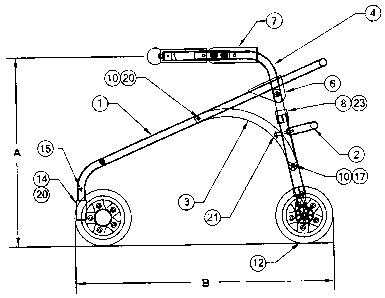
Referring now to the drawings, FIG. 1A and FIG. 1B shows the invention in its
position for use as a walker. The device has a front (main) support tube I
that is pivotably
connected to a rear (cross) assembly 2 through a main bracket 6. The front
support tube I
is fixed in its in-use position to the rear leg assembly by a radial cross
brace 3 located on
both sides of the walker. The brace 3 is mechanically fastened to the front
support tube by
a fastener 20 on one end, and a threaded hand knob 17 at the other end. The
threaded end
of the hand knob 17 runs through a hole in the end of the cross brace 3. The
knob is
captivated on one side of the cross brace by the knob and on the other side by
a retaining
ring.
The end of the front support tube 1 is terminated on both ends by a pivotable
dual
front wheel assembly 11 by means of a specially design adapter 14 (shown in
FIG. 11).
The adapter 14 is a bar that locates within and is mechanically attached to
the tubular ends
of the front support tube 1 and the tubular housings of the dual front wheel
assemblies 11.
Similarly, the lower end of the cross tube assembly 2 is terminated by a
single, non-
pivotable rear wheel assembly 1[2.
The terminal end of each of two handle assemblies 4 locates slidably within a
handle extension receiver 5 that is connected to the rear tube assembly 2 by
two dual tube
split clamps 9 on each side. The height of the handle assembly 4 is
incrementally
adjustable upwardly or downwardly via a removable double ball lock pin 21. In
its in-use
position, the pin 21 connects the handle assembly 4 to the handle extension
receiver 5
through matched holes in these components The pin 21 is inserted into a single
through
hole in the extension receiver 5 and one of a series of through holes in the
handle assembly
4. It is the matching hole selected in the handle assembly 4 that affixes the
handle height.
A handle extension stopper 8 prevents the handle assembly 4 from sliding down
into
handle extension 5 when the ball lock pin 21 is removed. The pin 21 is removed
either to
adjust the height of the handle assembly 4 relative to the handle extension
receiver 5, or, if
necessary, to remove the handle assembly 4 from the receiver 5 before folding
the walker
for storage. A flexible rear back strap 7 is removably affixed to the inside
of and adjusts in
height with the handle assemblies 4. Further, the rear back strap 7 may be
removed and
reattached horizontally relative to the position of handle assemblies 4.
CA 02634609 2008-06-11
-8-
As an example, a walker according to this embodiment, in this case
particularly
directed to a child user, may have the following approximate dimensions: A =
16 to 25"; B
= 25 to 27"; C = 13 to 15"; and D = 21 to 23".
FIG. 2 shows the configuration of the main support tube 1. The tube is bent in
a U-
shape configuration to outline the perimeter of the walker. Small diameter,
thin-walled
aluminum tubing, for example, with threaded rivet-style nuts are affixed to
minimize the
contribution of this member to the weight of the walker and reduce the
likelihood of hand
injuries caused by protruding fasteners. For example, 3/4" OD x 0.065 wall
6061-T6
aluminum tubing can be used.
FIG. 3 illustrates the rear assembly 2 comprising tube weldment that
incorporates
the cross support tube 23 and cross tube uprights 25. Aluminum upright end
fittings 27 are
each pinned with a coil spring pin 29 to terminate the ends of upright tubes
25. The end
fittings each accept a rear wheel assembly 12 axle at the lower end, and a
pivot axis
fastener (19 in FIG. iB) at the upper end.
The cross brace 3, shown in FIG. 4, is a structurally strong member that
connects
and bears the separation loading of the front support tube 1 and the cross
tube assembly 2.
The brace 3 is configured to run tangentially to both connecting members when
the walker
is in its in-use position to avoid contact with the child's legs and feet
during use. As an
example, the cross brace 3 can be fabricated with stainless stee1302.
FIG. 5 shows the right hand version of the handle assembly 4. A handle
extension
31 is the member that connects to the handle extension receiver 5 described
previously.
The handle extension 31 is bent in two planes - one bend to position the tube
inwardly to
place the hand grip 33 in close proximity to the child, and another bend to
position the
handle extension 31 in an orientation that is generally parallel to the
ground. The handle
35 is telescopically and removably connected to the horizontal end of the
handle extension
tube 31 by a pair of fasteners 36 and threaded back strap retainers 37.
Incremental
displacement of the handle 35 is achieved by removing the fasteners 36,
sliding the handle
axially along the tubular end of the handle extension tube 31 and relocating
the
fasteners 36 through the mating holes. The two back strap retainers 37 have a
flanged end
30 to retain one end of the rear back strap 7 through its adjustment holes.
The other end of the
CA 02634609 2008-06-11
-9-
rear back strap 7 is connected to a pair of retainers on the inside surface of
the other
handle. A soft, rubberized handgrip 33 is located axially over the handle 35
to provide a
comfortable support surface for the child's hand. A plastic bal139 terminates
the handle 35
to cue the child as to the location of his/her hand on the handgrip 33.
The tubular configuration of the handle extension receiver 5 is shown in FIG.
6. At
the upper end of the tube has a sawcut end with a stress relief hole at its
root. The upper
dual split clamp 9 locates over this end such that as the clamp is tightened,
the extension
receiver 5 elastically deflects to eliminate the clearance between the handle
assembly 4
and the extension receiver 5. This feature improves the responsiveness of the
walker to
movement at the handle by eliminating the play between the handle assembly 4
and the
handle extension receiver 5. For example, the handle extension receiver 5 can
be
fabricated from 7/8" OD x 0.049 wall 6061-T6 aluminum tubing.
The left hand version of the main bracket 6 is displayed in FIG. 7. The main
bracket 6 is made from an acetyl plastic, for example, to provide strength and
lightness for
the assembly. The cross bore in the bracket is sized to locate snuggly over
the front
support tube 1. This is achieved by providing an undersized lead in that
allows the bracket
6 to snap securely onto the front support tube 1. Since the plastic has
excellent bearing
characteristics, no additional bushings are provided to support the main pivot
fastener 19.
FIG. 8 shows the rear back strap 7 with adjustment holes 41 for connection to
the
back strap retainers 37 of the handle assemblies 4. The rear back strap 7 can
be an
extendable thermoplastic rubber that provides strength and a firm contact
surface at the
level of the child user's hips. For example, the rear back strap 7 can be
SantopreneTM
extrusion. Incremental horizontal translation of the rear back strap 7 is
achieved by pulling
the strap ends away from the handle 35 such that the two back strap retainers
37 are pulled
through an adjacent pair of adjustment holes 41. Another pair of adjacent
adjustment holes
41 is relocated over the back strap retainers 37 and stretched elastically
over the flange of
the back strap retainers to secure the strap to the handle 35.
FIG. 9 displays the dual split clamp 9 that connects the handle extension
receiver 5
to the cross support tube assembly 2. A through hole in one half of the clamp
and a
CA 02634609 2008-06-11
- 10-
threaded hole in the other half allows a fastener to apply gripping forces
simultaneously to
the handle extension tube 5 and cross support tube assembly 2.
The rear wheel assembly 12 is shown in FIG. 10. This configuration is for the
right
hand rear wheel. The left hand version is the mirror image of this
arrangement. The rear
wheel 43 is rotationally affixed through a shoulder screw axle 45 to the
upright end fitting
47 at the end of the cross support tube assembly 2. It is preferable that the
rear wheels of
the walker be equipped with an anti-rollback means, i.e. only forward movement
is
allowed. For example, an anti-rollback finger 49 can be pivotably connected to
the cross
support tube assembly 2 and rests freely on the studded hub of the wheel 43.
As the wheel
43 rotates rearward (i.e., moves clockwise in the side view), the finger 49
rotates
downward (counterclockwise) between two studs. Since the anti-rollback finger
49
reaches its limit of rotation, the wheel 43 locks and cannot continue to move
in a
clockwise motion. As the walker moves forward, the wheel 43 rotates in a
counterclockwise orientation and the finger 49 rotates about the pivot in a
clockwise
motion. The anti-rollback finger rests on the crest of the studs as the wheel
turns, thereby
providing unhindered motion of the wheel 43.
FIG. 11 displays the front and side views of the wheel adapter 14.
FIG. 12 illustrates the stability cuff in its in-use position as secured to
the front
support tube 1.
FIG. 13 shows the open view of the outside surface of the removable, fabric
stability cuff. The outer skin is preferably non-expandable to retain the
shape of the cuff
when wrapped around the end front support tube 1. Two nylon retention straps
with hook
and loop ends and D-style rings provide a removable, but secure attachment to
the front
support tube 1.
FIG. 14 displays the inner surface of the stability cuff and the pocket that
retains
the counterweight. According to this particular embodiment, three pockets are
provided -
one for each weight. The pocket envelops and retains the weight within the
stretchy inner
skin. The pockets each have a slot at one end to allow the weight to be
readily inserted into
or removed from the stability cuff.
CA 02634609 2008-06-11
-11-
FIG. 15 shows the three weights that are used within the cuff to provide
stability
adjustment to the walker. Adding weights to the cuff increases the rearward
and lateral
stability of the walker. Removing weights from the stability cuff reduces the
rearward and
lateral stability, and thereby increases the maneuverability of the walker.
Preferably, two
weighted stability cuffs are located at the terminating ends of the front
support tube 1. As
an example, each weighted cuff can be 1.5 pounds, providing a total addition
of 3 pounds
to the front end. If the walker itself is 6.5 pounds, for example, which is
achievable if high
strength, low weight structural components are implemented as described above,
the
addition of 3 pounds to the front end would yield a significant difference in
the stability of
the walker.
Other configurations are possible. For example, one or more stability cuffs
could
be provided at the terminating ends of the cross support tube assembly 2 to
increase the
forward stability of the walker, additional pockets could be provided to
increase the
ballasting of the walker, and the cuff could be slidably attached to the front
support tube 1
and moved up the length of the tube to fine tune the stability of the walker.
Other locations
of the counterweights could be used in alternative embodiments. For example,
removable
weights could be placed in the backpack to increase the rearward stability of
the walker. In
sum, the removable weighted stability cuffs enable quick and easy modification
of the
stability characteristics of the walker.
FIG. 16 illustrates the backpack in its in use position on the walker. The
backpack
can be removably attached between the horizontal member of the front support
tube I and
the cross tube of the cross support tube assembly 2. The upper strap wraps
around the
upper front support tube and connects to a mating hook and loop fastener strip
sewn on the
backpack. A lower strap wraps around the rear support tube to provide lower
securement
for the bag. According to one configuration, the flap of the backpack faces
toward the
child user to provide easy access to the interual contents. Compartments
within the bag
and bilateral mesh drink holders provide storage for school supplies, school
notes, toys,
snacks, and drinking boxes. The center of mass of the backpack is located
inside the axles
of the rear wheels to prevent a loss of rearward stability as the weight of
bag contents
increases.
FIG. 17 shows the walker in its folded position.
CA 02634609 2008-06-11
12-
F[G. 18 illustrates child walking with walker.
The embodiment of the present invention described above addresses many of the
shortcomings of existing products. In particular, the walker device of the
present invention
may comprise one or more of up to seven features typically not found on
commercial
walkers, including: (a) a light tubular frame configured to ease transfers and
improve
access to tables in areas frequented by preschoolers and primary school-age
children; (b) a
handle that is adjustable in height, width and depth to adapt to child sizing,
growth, and
mobility needs; (c) a flexible back strap that can be adjusted in height and
depth to provide
circumferential contact of the lower back; (d) one or more weighted stability
cuffs
removably connected to positions on the walker to adjust the handling and
stability of the
walker; (e) a tangential brace affixed to strengthen the tubular frame when in
use, and
pivotable to allow the frame to be folded for storage; (f) two main brackets
that
interconnect key structural members of the walker; and (g) a
compartmentalized, storage
backpack to carry children's toys, snacks, and school supplies.
It should be expressly understood that the dimensions and configuration
illustrated
in the figures are provided by way of example only and the walker could be
easily
modified or adjusted by a person skilled in the art, depending on the
particular application.
It will be appreciated by those skilled in the art that other variations of
the one or more
embodiments described herein are possible and may be practised without
departing from
the scope of the present invention.