Note: Descriptions are shown in the official language in which they were submitted.
CA 02634716 2008-06-20
WO 2007/078603 PCT/US2006/046930
APPARATUS AND METHODS FOR LOADING
OF AN IOL INJECTOR
Field of Invention
The present invention relates to intraocular lens (IOL) injectors, and more
particularly to loading apparatus and methods for IOL injectors.
Background of the Invention
IOLs are artificial lenses used to replace natural crystalline lenses of eyes
when
the natural lenses are diseased or otherwise impaired. Under some
circumstances a
natural lens may remain in an eye together with an implanted IOL. IOLs may be
placed
in either the posterior chamber or anterior chamber of an eye.
IOLs come in a variety of configurations and materials. Various instruments
and
methods fo:r implanting such IOLs in an eye are known. Typically, an incision
is made
in a patient's cornea and an IOL is inserted into the eye through the
incision. In one
technique, a surgeon uses surgical. forceps having opposing blades to grasp
the IOL and
insert it through the incision into the eye. While this technique is still
practiced today,
more and more surgeons are using IOL injectors which offer advantages such as
affording a surgeon more control when inserting an IOL into an eye and
permitting
insertion of IOLs through smaller incisions. Smaller incision sizes (e.g.,
less than about
3mm) are preferred over larger incisions (e.g., about 3.2 to 5+mm) since
smaller
incisions have been attributed to reduced post-surgical healing time and
reduced
complications such as induced astigmatism.
In order for an IOL to fit through a smaller incision, it is typically folded
and/or
compressed prior to entering the eye where they will assume their original
unfolded/uncompressed shape. Since IOLs are very small and delicate articles
of
manufacture, great care must be taken in their handling, both as they are
loaded into an
injector and as the lens is injected into a patient's eye.
It is important that an IOL be expelled from the tip of the IOL injector and
into
the eye in an undamaged condition and in a predictable orientation. Should an
IOL be
damaged or expelled from the injector in an incorrect orientation, a surgeon
must remove
or further manipulate the IOL in the eye, possibly resulting in trauma to the
surrounding
I
CA 02634716 2008-06-20
WO 2007/078603 PCT/US2006/046930
tissues of the eye. To achieve proper delivery of an IOL, consistent loading
of the IOL
into the injector device with a minimum opportunity for damaging the IOL is
desirable.
Various IOL injectors and other devices have been proposed which attempt to
address issues related to loading, yet there remains a need for an IOL
injector which
improves consistency of loading and reduces the likelihood of damage to an
IOL.
Summary
Aspects of the present invention are directed to an IOL injector comprising a
loading chamber comprising a component that when being closed folds the lens.
Additional aspects of the present invention are directed to a vial for
maintaining an IOL
prior to loading. The vial includes an injector guide that receives an
injector such that
when the injector is rotated a folded IOL can be obtained in the injector. In
some
embodiments, the injector and vial are provided in a combination. As defined
here in "a
combination" includes but is not limited to arrangements in which the objects
in the
combination are: packaged and are not connected to one another.
Other aspects of the present invention are directed to an injector having an
opening to a loading chamber, the opening being defined by a tapered edge.
Additional
aspects of the present invention are directed to an IOL vial comprising a
convexly curved
.interior surface and a flexible arm adapted to maintain an IOL against a
surface opposite
the convexly curved interior surface- In some embodiments, the injector having
tapered
edge and the vial having a flexible arm are provided in a combination.
A first aspect of the invention is directed to an IOL injector, comprising an
injector body having a loading chamber and defining a lumen extending along a
longitudinal axis. An opening to the loading chamber being defined by a
tapered edge,
and the edge extends in the direction of the longitudinal axis.
In some embodiments, the tapered edge is aligned parallel to the longitudinal
axis.
The tapered edge may extend along the entire length of the opening. In some
embodiments, the tapered edge is sharp. The opening to the loading chamber may
be
further defined by a non-tapered edge, the non-tapered edge extending in the
direction of
the longitudinal axis. In some embodiments, the opening to the loading chamber
is
further defined by a second edge, the second edge extending parallel to the
direction of
the longitudinal axis, and a cross section of the lumen perpendicular to the
longitudinal
2
CA 02634716 2012-01-25
axis at the loading chamber is substantially circular. In such embodiments,
the radial
distance from the center of the loading chamber to the tapered edge in the
cross section
may be greater than the radial distance from the center of the loading chamber
to the
second edge in the cross section.
In some embodiments, the injector further comprises a concave outer surface
disposed substantially opposite the opening. The injector may be in a
combination with
a vial comprising a convex interior surface and a flexible arm adapted to
maintain an
IOL against a surface opposite the convex interior surface. In some
embodiments, the
concave exterior surface and the convex interior surface have substantially
the same
radius of curvature.
Another aspect of the invention is directed to an IOL vial comprising a
convexly
curved interior surface and a flexible arm adapted to maintain an IOL against
a surface
opposite the convexly curved surface. The vial may comprise a vial base
wherein the
flexible arm is hingedly attached to the vial base.
Yet another aspect of the invention is directed to a method of loading an IOL
injector
comprising an injector body and a loading chamber with an IOL, the method
comprising
inserting the loading chamber into a vial that contains an IOL; and rotating
the IOL injector
body relative to at least a portion of the vial to obtain the IOL in the
loading chamber.
In some embodiments, the IOL injector has a lumen with a longitudinal axis and
the
step of rotating comprises rotation about an axis parallel to the longitudinal
axis. The step of
rotating the IOL injector body may cause rotation of a first loading chamber
component
relative to a second loading chamber component. In some embodiments, the step
of rotating
the IOL injector body comprises folding the IOL to obtain the IOL in a folded
configuration
in the loading chamber. In some embodiments, the IOL is ready for injection
after the step of
rotating.
In some embodiments, the IOL injector has a lumen, and upon rotation, a first
loading chamber component and a second loading chamber component combine to
form
a portion of the lumen. The portion of the lumen may be a rotationally
complete portion
of the lumen. In some embodiments, the first loading chamber component and the
second loading chamber component become attached to one another after
rotation.
The step of inserting may comprise inserting the injector along a guide. The
step of
inserting may result in detaching the lens from a lens holder.
3
CA 02634716 2008-06-20
WO 2007/078603 PCT/US2006/046930
The term "lens contact surface" is defined herein as a surface arranged to
contact
an IOL lens after the loading chamber is closed. An injector having an IOL
that is
"ready for delivery" is an injector that is in a condition such that actuation
of its IOL
ejection apparatus (e.g., a plunger) results in ejection of the IOL from the
injector.
Brief Description of the Drawings
Illustrative, non-limiting embodiments of the present invention will be
described by way
of example with reference to the accompanying drawings, in which the same
reference
number is used to designate the same or similar components in different
figures, and in
which:
FIG. 1A is a perspective view of an exemplary embodiment of an injector
according to aspects of the present invention having an open loading chamber;
FIG. 1B is a perspective view of an exemplary embodiment of a injector
according to aspects of the present invention having a closed loading chamber;
FIG. 1 C is a perspective view of an exemplary embodiment of a injector
according to aspects of the present invention having a tip attached;
FIG. 2A is a perspective view of an exemplary embodiment of a vial according
to
aspects of the present invention;
FIGs. 2B-C are side views of the exemplary embodiment of the vial illustrated
in
FIG. 2A;
FIG. 3A is a plan view of an exemplary embodiment of a lens holder according
to
aspects of the present invention;
FIG. 3B is a side view of the exemplary embodiment of the lens holder
illustrated
in FIG. 3A;
FIG. 4 is a perspective view of the exemplary embodiment of an injector as
illustrated in FIG. IA engaged with the exemplary embodiment of a vial as
illustrated in
FIG. 2A, in which a portion of the vial is broken away;
FIGs. 5A-5C illustrate steps for loading an injector according to aspects of
the
present invention;
FIG. 6A is a perspective view of a second exemplary embodiment of an injector
according to aspects of the present invention having an open loading chamber;
4
CA 02634716 2008-06-20
WO 2007/078603 PCT/US2006/046930
FIG. 6B is a perspective view of the second exemplary embodiment of the
injector according to aspects of the present invention having a closed loading
chamber;
FIG. 6C is a side view of the second exemplary embodiment illustrating a
loading
chamber opening;
FIG. 7 is a perspective view of the second exemplary embodiment of an injector
as illustrated in FIG. 6A engaged with a second exemplary embodiment of a
vial, in
which a portion of the vial is broken away;
FIGs. 8A-8B illustrate steps for loading an injector according to aspects of
the
present invention; and
FIG. 9 is a perspective view of an exemplary embodiment of a flexible arm.
Detailed Description
FIG. 1A is a perspective view of an exemplary embodiment of an IOL injector
100 according to aspects of the present invention. As illustrated in FIG. 1A,
IOL injector
100 has an open loading chamber and a detached tip 175. Injector 100 includes
a lumen
having a longitudinal axis Z. An injector body segment 110 defines a portion
L' of the
lumen. As described below, another portion of the lumen is provided by the
loading
chamber 120 when it is closed.
A first loading chamber component 120a is coupled to the injector body
segment;
and a second loading chamber component 120b is hingedly coupled to the first
loading
chamber component such that the second loading chamber component is capable of
rotating about a second axis Y that is parallel to longitudinal axis Z. In
some
embodiments, the second axis maybe aligned with a wall of the injector body as
illustrated in FIGs. 1A-iC. However, coincidence is not necessary and the
second axis
may be oi:fset from the wall of the lumen.
First loading chamber component 120a may be coupled to injector body 100
segment 110 in any suitable manner. For example, the first loading chamber
component
may be rigidly connected to the injector body. In some embodiments, the first
loading
chamber component may be integrally formed (e.g., molded as a single part)
with the
injector body segment. Other suitable techniques of attachment include, but
are not
limited to snap fit or compression fit or by using a connector such as a screw
or other
threaded structure.
CA 02634716 2012-01-25
As illustrated in FIG. 1B, when second loading chamber component 120b is
rotated about second axis Y such that the loading chamber is closed, the first
loading
chamber component and the second loading chamber component combine to form a
second portion L" of the lumen. Preferably, the first loading chamber
component and
the second loading chamber component fixedly couple together when the loading
chamber is closed such that they maintain a closed loading chamber after
rotation of the
second loading chamber component. For example, a molded snap fit structure may
be
provided on the first and second loading chamber components (i.e., they are
configured
to snap together). As illustrated in FIG. IA, in some embodiments, the snap
fit structure
may comprise a projection 121b on one of the bottom surface of first loading
chamber
component and the top surface of second loading chamber component, and a
detent 1214,
on the other of bottom surface 121 a and top surface 121 a.
Also as illustrated in FIGs. IA and 1B, second loading chamber component 120b
comprises a lens contact surface 122. It is to be appreciated that in the
illustrated
embodiment the second loading chamber component is configured and arranged to
fold
an IOL 150 (also referred to herein simply as a "lens"), using the lens
contact surface,
upon rotation of the second loading chamber component about second axis Y. As
illustrated in FIG. 1B, in some embodiments, the first and second loading
chamber
components form a rotationally complete portion L" of the lumen.
Upon rotation of the second loading chamber component, IOL 150 is located in
loading chamber ready for delivery (i.e., the lens is located such that upon
depressing of
plunger 130, IOL 150 is expelled from the injector). Plunger 180 is aligned in
the lumen
such that tip 182 advances the lens after it has been obtained in the
injector. The tip may
be a conventional fork shaped tip or a soft silicone tip as is known in the
art. As illustrated
in FIG. IG, according some embodiments of the invention, upon rotation of the
second
loading chamber component, such that the loading chamber is closed, a tip 175
may be
attached to an end of the loading chamber.
FIG. 2A is a perspective view of an exemplary embodiment of an IOL vial 200
according to aspects of the present invention. Vial 200, comprises a vial base
210, and
an IOL holder mount including a first support 220a and a second support 220b
disposed
in the vial base. Vial 200 also includes an injector guide 230 that is
configured to be
rotatably mounted in the vial base. As discussed in greater detail below with
reference to
6
CA 02634716 2012-01-25
FIGs. 5A-5C, an IOL injector (e.g., injector 100 illustrated in FIG. IA) can
be inserted
along injector guide 230 and rotated such that a folded IOL can be obtained in
the
injector. As illustrated in FIG. 2A, injector guide 230 maybe coupled to a
guide support
235 that maintains injector guide 230 relative to vial base and supports 220a
and 220b.
As discussed in greater detail below with reference to FIG. 5B, the guide
support 235
extends below the bottom of guide 230.
It is to be appreciated that, in the illustrated embodiment, guide support 235
is
cylindrical so as to conform to the shape of the vial base. The guide support
may form a
continuous cylinder or have a gap. Also, as illustrated in greater detail in
FIG. 5A, guide
support 235 is sized to fit between a sidewall 214 of the vial base and a
fixed stop 212.
FIG. 2B illustrates holder mount 220a of a vial base 210 in greater detail.
Holder
mount 220a comprises a first prong 221a and a second prong 22 lb. FIG. 2C
illustrates
holder mount 220b of vial base 210 in greater detail. Holder mount 220b
comprises a
first prong 222a and a second prong 222b. In some embodiments, prong 222b is
slightly
lower than prong 222a. As described below, the space between prong 221a and
prong
221 b, and the space between prong 222a and prong 222b are selected so that
holder
mounts 220a and 220b slidably hold a lens holder as described in greater
detail below.
FIGs. 3A and 3B illustrate an exemplary embodiment of a lens holder 300
suitable for use with the injector 100 and vial 200. An IOL 350 is disposed in
a valley
310 between two ridges 315a and 315b. The width W of the valley is selected
such that
IOL 350 can be maintained between the ridges due to friction between the. IOL
haptics
352a-352d and the ridges 315a and 315b. Holder 300 has a thickness T at the
ridges. As
discussed below, IOL 350 may be removed from mount 300 by application a force
F to a
side of IOL 350 such that force F overcomes the friction holding IOL between
the ridges.
It is to be appreciated that any suitable IOL and IOL holder may be used with
aspects of
the present invention. For example, the IOL may have any suitable optic shape
and may
have any suitable number of haptics (e.g., one, two or three), and the IOL
holder may
have any suitable shape.
FIG. 4 is a perspective view of injector body 110 as illustrated in FIG. IA
approaching engagement with the exemplary embodiment of a vial 200
as illustrated in FIG. 2A. Injector 100 can be inserted along injector guide
230 (in the
7
CA 02634716 2012-01-25
direction indicated by arrow 1) and injector body 110 is rotated (in the
direction of
arrow 2) such that a folded IOL 350 can be obtained in the loading chamber of
the injector.
It is to be appreciated that although in some applications it is advantageous
to
provide and/or use injector 100 with a vial 200, injector 100 maybe used with
any
suitable structure capable of maintaining an IOL such that the second loading
chamber
component can be used to interact with the IOL in a manner such that the IOL
is
obtained in loading chamber.
FIGs. 5A-5C illustrate an exemplary progression of steps for loading an
injector
body 110 with an IOL 350 according to aspects of the present invention. It is
to be
appreciated that only a portion of the injector 100 proximate the loading
chamber
120 is illustrated in FIGs. 5A-5C to avoid obfuscation.
As illustrated in FIG. SA, IOL holder 300 is supported by IOL supports 220a
and
220b of IOL holder support 220. A thickness T (see FIG. 3B) is sized relative
to the
distance between prongs 221 a and 22lb (see FIG. 2A), and the distance between
prongs
222a and 222b (see FIG. 2B) so as to form a friction fit between prongs 221a
and 221b
of IOL support 220a and to form a friction fit between prongs 221 b and 222b
of IOL
support 220b. Accordingly, lens holder 300 is slidably held by the supports
220a and
220b such that upon application of a force T to the lens holder, IOL holder
300 slides
between pair of prongs 221 a, 222a and pair or prongs 221b, 222b toward the
bottom of
the vial. It is to be appreciated that as IOL holder 300 slides between the
prongs, IOL
350 is contacted by a projection 505 such that a force F, which is capable of
overcoming
the friction between haptics 352a 352d and holder 300 (as described above with
reference to FIG. 3A), is applied to lens 350. Lens 350 can thereby be
detached from the
holder 300. Projection 505 maybe attached to or separate of vial base 210.
Vial base
210 may be provided with a holder (not shown), such as a hollow cylinder,
disposed on
its bottom to facilitate positioning of projection 505. Fixed stop 212 is
included in FIG.
SA for clarity.
FIG. 5B illustrates IOL holder 300 after it has been displaced in the
direction of
arrow I (i.e., toward the bottom of vial 300) a sufficient distance such that
IOL 350 is
completely detached from IOL holder 300 and is located proximate loading
chamber 120
(i.e., the lens is proximate first loading chamber component 120a and second
loading
chamber 120b).
8
CA 02634716 2012-01-25
It is to be appreciated that, as illustrated in FIG. 5B, injector 100 is
pushed
into the vial base 210 a distance such that first loading chamber component
120a is at
least a small distance above holder mount 220a and a small distance below
injector guide
230, thus exposing the bottom of first loading chamber component 120a. As
discussed
above, with reference to FIG. 2A, the guide support 235 extends below the
bottom of
injector guide 230. Accordingly, there is a separation between the bottom of
guide 230
and the top of support 220a such that the bottom of first loading chamber
component
120a is exposed during rotation.
Additionally, the top of second loading chamber component 120b extends above
holder mount 220b, such that upon rotation of the injector body
(in the direction of arrow 2) as
indicated in FIG. SC, the bottom of first loading chamber component 120a and
the top of
second loading chamber component 120b contact one another and become attached
to
one another, for example using a snap fit as discussed above with reference to
FIG. IA.
Accordingly, upon rotation of the injector body 110, the loading chamber is
closed and a
folded IOL 150 is achieved in injector 100. As discussed above with reference
to FIG.
2C, second. prong 222b may be slightly lower than prong 222a, thereby
facilitating
closure. In some embodiments, fixed stop 212 operates to prevent over rotation
of the
second loading chamber component relative to the first loading chamber
component.
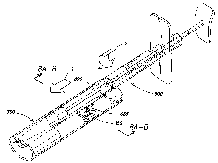
FIG. 6A is a perspective view of a second exemplary embodiment of an IOL
injector 600 according to aspects of the present invention. As illustrated in
FIG. 6A, the
injector has an open loading chamber 620. Injector 600 comprises an injector
body 610
defining a lumen extending along a longitudinal axis Z. The injector has an
opening 624
to the loading chamber that is defined at least in part by a tapered edge 625
extending in
the direction of longitudinal axis Z.
Tapered edge 625 is illustrated in the cross-sectional view of injector 600 in
FIG.
8A. As illustrated in FIG. 8A, in some embodiments, the lumen has a
substantially
circular cross section. However, the lumen maybe elliptical or oval. In some
embodiments, having a substantially circular cross section, it is advantageous
that
tapered edge 625 be located further from a center K of the substantially
circular lumen
(i.e., a distance d2 from K) than an opposing edge 626 of opening 624 (i.e., a
distance d2
from K) thereby facilitating loading a lens by scooping the lens into the
loading chamber
as described below. In some embodiments, regardless of the shape of the lumen,
tapered
9
CA 02634716 2012-01-25
edge 625 is located further from the middle of surface 622 than opposing edge
626. It is
to be appreciated that tapered edge 625 may be sharp. It is also to be
appreciated that to
be sharp, an edge need not come to point at a microscopic level.
Referring to FIG. 6C, opening 624 is illustrated in a side view of injector
600.
The length of tapered edge 625 can extend along the entire length L of opening
624 (e.g.,
the opening may be rectangular and the tapered edge may extend along a side of
the
rectangle) or the tapered edge can extend along only a portion of length L
that is
adequate to engage an IOL in the manner discussed below with reference to
FIGs. 8A
and &B. It is also to be appreciated that tapered edge 625 can be aligned
parallel to axis
Z; however, tapered edge 625 may be disposed other than parallel so long as it
extends at
least some distance along the direction of axis Z. In some embodiments, only
edge 625
is tapered and edge 626 is non-tapered.
Referring again to FIG. 6A, in some embodiments, injector 600 may have an
exterior surface 622 that is configured to facilitate loading of a lens into
the injector in a
manner as discussed below with reference to FIGs. 8A and 8B. Injector tip 175
may be
integrated with the remainder of injector 600
or may be attachable thereto using any suitable technique.
As illustrated in FIGs. 6A and 6B, a door 630 may be provided which can be
closed to maintain a lens within the loading chamber of the injector 600.
Although the
illustrated door is configured and arranged to slide along injector body 610
into a closed
position, the door may be disposed on a hinge or may simply snap into a closed
position.
Plunger 180 is aligned in the lumen such that tip 182 advances the lens after
it has been
obtained in the injector. The tip may be conventional fork shaped tip or a
soft silicone
tip as is known in the art.
FIG. 7 is a perspective view of the second exemplary embodiment of an injector
as illustrated in FIG. 6A that is engaged with a second exemplary embodiment
of an IOL
vial 700. As discussed in greater detail with reference to FIGs. 8A and 8B,
injector 600
can be inserted (in the direction indicated by arrow 1) into vial 700; and the
injector body
can be rotated relative to the vial (in the direction indicated by arrow 2) to
obtain the IOL
in the IOL injector. In some embodiments, the injector is rotated about a
curved
interior surface 640 of the vial by contacting surface 640 with at least a
portion of surface
622 of the injector.
CA 02634716 2012-01-25
FIGS. 8A-8B are cross-sectional views taken along line 8A -D of FIG. 6A that
illustrate steps for loading an injector according to aspects of the present
invention. As
discussed above, injector 600 is inserted into vial 700. Vial 700 is provided
with a
flexible arm 635 adapted to maintain an IOL 350 against a surface of the vial.
Injector
600 may be rotated relative to the vial to obtain the IOL in the IOL injector.
In some embodiments, a portion of an interior surface of the vial is selected
to
conform to an exterior surface of the injector in a region proximate opening
624. For
example, in some embodiments surface 622, which may be located on a
substantially
opposite side of injector 600 from opening 624, has concave curvature that
substantially
matches a convexly curved interior surface 640 of vial 700 (e.g., they have
substantially
the same radius of curvature and may share a center of curvature Q.
Accordingly,
injector 600 can be rotated about center of curvature C (i.e., in the
direction of arrow 2)
in a stable and reliable manner. In some embodiments, surface 622 is convex
and
surface 640 is concave.
In some embodiments, the distance R from surface 622 to tapered edge 625 is
substantially equal to the distance from vial surface 640 to vial surface 612
(e.g., over an
angle 0), such that the injector 600 remains contained between surfaces 640
and 612
upon rotation, thereby adding to the stability and reliability of the rotation
of injector 600.
It is to be appreciated that flexible arm 635 maintains IOL 350 against a
surface disposed
opposite curved surface 640. Although flexible arm 635 is illustrated having a
hook
shaped cross section, any suitable shape may be employed. For example an arm
having a
simple straight shape that collapses upon the application of sheer force as
would occur
when the inserter is rotated about the curved surface 640 and thereby contacts
a side of
the flexible arm. Flexible arm 635 may be attached to the vial base at
location 645 using
a hinge or other suitable rotatable structure, or the flexibility of flexible
arm may be
selected such that the flexible arm folds or wraps around location 645 upon
contact with
the injector without the use of a hinge.
As illustrated in FIG. 8B, injector 600 may be rotated relative to the vial in
the
manner described above (i.e., with surface 622 of the inserter contacting
surface 640 of
the vial) to obtain the IOL in the IOL injector. Upon rotation of the injector
about
center of curvature C, tapered edge 625 engages lens 350 and in a shovel-like
manner
lifts the lens into the loading chamber. A stop 610 maybe located to hold the
lens in
11
CA 02634716 2008-06-20
WO 2007/078603 PCT/US2006/046930
place as the lens is contacted by the tapered edge. It is to be appreciated
that the curved
shape of the interior of the loading chamber causes the lens to fold the IOL
as the IOL
encounters the interior surface of the lumen. As the lens is engaged by the
tapered edge,
a portion of the inserter 602 engages flexible arm 625 thereby moving the
flexible arm
out the way as illustrated in FIG. 8B.
It is to be appreciated that although in some application is advantageous to
provide and/or use injector 600 with a vial 700, injector 600 may be used with
any
suitable structure capable of maintaining an IOL such that the tapered edge
625 can be
used to interact with the IOL in a manner such that the IOL is obtained in
loading
chamber 620.
FIG. 9 is a perspective view of an embodiment of a flexible arm 635
illustrating
further details of the flexible arm. The arm is configured to maintain lens
350 against a
wall of the vial as discussed above, and flexible enough such that the
movement about
attachment 645 allow arm to be moved away from lens 350 during loading as
discussed
above with reference to FIG. 8B. The arm preferably has a shape such that
contact with
the lens is made over a substantial area to avoid damage to the lens.
Preferably, the
portion of the arm contacting the lens is smooth to facilitate movement away
or sliding
along the lens without causing damage.
Injectors and vials as described herein are preferably made from a
biocompatible
and sterilizable material. For example, the injector and/or vial (including
the flexible
arm) may be made of polypropylene or polyetherimide (e.g. UltemTM available
from
General Electric Corp.). In some embodiments, it is advantageous if the
material used
for an injector and/or vial is transparent to facilitate viewing of the lens
during loading.
Having thus described the inventive concepts and a number of exemplary
embodiments, it will be apparent to those skilled in the art that the
invention may be
implemented in various ways, and that modifications and improvements will
readily
occur to such persons. Thus, the embodiments are not intended to be limiting
and
presented by way of example only. The invention is limited only as required by
the
following claims and equivalents thereto.
What is claimed is:
12