Note: Descriptions are shown in the official language in which they were submitted.
CA 02634912 2008-06-23
WO 2007/073281 1 PCT/SE2006/001428
A heat exchanger mixing system
Present invention relates to a heat exchanger mixing system, use of a heat
exchanger mixing system, and a process for mixing fluids.
Background of invention
Mixers are often used for different applications wherein it is important that
the
contact between reactants, fluids, etc. is as great as possible. The contact
is
improved by turbulence and turbulence is effectuated by the use of different
types of mixing elements. Due to the need of heat transfer in many of these
operations the mixers are usually combined with heat exchangers.
A great number of combinations of mixers and heat exchangers are known from
literature for example WO 97/21061 discloses a plurality of cooperating
assemblies each comprising a central tube, provided with one or more static
mixing elements, an annular space surrounding the tube and a shell tube. The
annular spaces form continues compartments, which enables transfer of heat to
and from the process. A mixing element attached to an opening of a heat
exchanger is disclosed by WO 2002/46679.
A device for processing fluids by controlling the residence time and/or the
reaction time by the use of a single block or a set of several blocks or
sublocks
placed one next to the other are disclosed by US patent application published
under number US 2004/0109798.
One problem with the combined mixer heat exchangers of the prior art is the
length of transportation between mixer and reaction chamber. This results in
inferior heat transfer, temperature control, and spacious equipments. Thus,
one
object of the present invention is to design equipment with a more effective
heat
balance, and another object is to design a more compact mixer heat exchange
system.
CA 02634912 2013-02-28
2
The invention
Accordingly, the present invention provides a compact system, which enables a
more sufficient heat balance. Thus, the present invention relates to a heat
exchanger
mixing system comprising at least one heat exchanger zone, at least one
connection plate
having one or more mixing units, at least four fluid transfer corners per
connection plate,
wherein each fluid transfer corner, herein after called corner or corners,
being either a
blind passage corner, a through passage corner, a single passage corner, or a
double
passage corner. The one or more mixing units are provided with mixing
elements. The
blind corner acts as a stopper and no fluid passes through it. A through
passage corner may
pass fluids through a connection plate without mixing the fluids with any
other fluids, or a
through passage corner may be a passage into a connection plate from the
outside of the
plate. A single corner is directing a flow of fluids in any pre-designed angle
compared to
the inlet angle, and the corner may be used for directing a flow of fluids
into a connection
plate or out of a connection plate, or may direct the flow to by-pass a
connection plate. A
double corner is transferring two flow of fluids in different directions
without mixing the
two flows. Double comers may be used for adding flows of fluids to the system.
Examples
of corners, which may be used according to the invention, are disclosed in US
4373579
and WO 99/51926. The invention comprises any type suitable corners. The
corners are
connected to for example a connection plate, a mixing unit, a reactor zone, a
heat
exchanger zone, or combinations thereof. Fluids may be transferred by the
comers into a
connection plate or out a connection plate, or if the corner is a double
corner it may
transfer both process fluids and heat exchanger fluids for instance into or
out of a
connection plate, but a double comer may also transfer two process fluids to
two mixing
units, to two reactor zones, to two heat exchanger zones, or combinations
thereof.
The heat exchanger zone or zones may be heat exchanger plates arranged on one
or
both sides of the at least one connection plate, or be placed between two or
more
connection plates. According to another alternative the heat exchanger zone
may be a
space inside a connection plate outside an internal mixing unit or may the
heat exchanger
zone surround an externally connected mixing zone. Thus, the at least one heat
exchanger
zone may be placed inside, outside, or both of the at least one connection
plate. Yet
another alternative the at least one heat exchanger zone may be placed as a
combination of
heat exchanger plates arranged on one or both sides of the at least one
connection plate
CA 02634912 2013-02-28
3
and of heat exchanger zones placed inside, outside, or both of the at least
one connection
plate.
According to one alternative two, three or more connection plates may be
directly
connected to each other between for instance two or more packages of heat
exchanger
plates, but as an alternative it may not be necessary that the heat exchange
mixing system
has heat exchanger plates, instead the system may have heat exchanging zones
either
externally, internally or both.
The connection plate may have a shape, which may be essentially square or
rectangular, but any shape is possible as long as the performance of the heat
exchanger
mixing system produces the aimed results. The connection plate may have a
section,
which may harbour mixing units, heat exchanger fluids, process fluids or
combinations
thereof. The at least one connection plate may have one or more mixing units
connected
externally to, arranged internally within, or both, the at least one
connection plate. Inlets
and outlets of the connection plate may be connected to heat exchanger fluids
or process
fluids through the comers and the at least one connection plate may have at
least one inlet
and at least one outlet for fluids. The one or more mixing units may be
connected
externally to the connection plate. One process fluid may be transferred in a
mixing unit
inside the connection plate and another process fluid may be transferred in an
externally
placed mixing unit. The mixed process fluids may be combined and mixed
together in yet
another mixing unit all depending what type of reaction or physical step the
fluids are
passing. The connection plate may harbour one or more mixing units internally,
one may
be inside a tube or other type of closed channel and another may be a mixing
unit
surrounding the tube or the other type of closed channel. Another alternative
the
connection plate may harbour one or more mixing units arranged internally and
at least
one inlet and at least one outlet for heat exchanger fluids. The connection
plate may be
hermetically sealed. The corners may be integrated in the at least one of the
connection
plates.
The mixing units may be provided with mixing elements. The mixing elements
may have wings, fins, or other mixing promoting arrangements, the mixing
elements could
be nets, metallic foams, mesh, fins etc. The mixing elements may be selected
from the
group consisting of static mixers, helical mixers, combination of right- and
left-turned
mixer blades, vortex mixers, dynamic mixing elements, lanced offset
turbulators, flow
CA 02634912 2013-02-28
4
controlling inserts, metallic foams, mesh, etc. The mixing unit may be mixing
elements
such as flow controlling inserts disclosed by WO 2004/045761. The mixing unit
and the
mixing elements may be manufactured of any suitable alloy, stainless steel,
HasteHoy ,
Inconel , flouropolymer, polyester, plastics, polyvinyl chloride (PVC), nylon,
glassfibers,
ceramics, (polypropylene, polystyrene, polycarbonate, polyethylene,
poly(methyl)
(met)acrylate, poly ether etherketone (PEEK), or combinations thereof.
The heat exchanger system according to the invention may have according to one
alternative embodiment one or more injection ports connected to for instance
one or more
corners or along the sides of one or more connection plates. The injection
ports may be
used for additives, reactants, etc. or for test sampling, monitoring of the
flow of fluids etc.
According to one alternative an injection port may be connected to a blind
passage corner,
a through passage corner, a single passage corner, or a double passage corner.
The heat exchanger system may be brazed, welded or both, or parts of the
system
may be brazed, welded or both, and the system may be clamped in a framework
having at
least two end plates, but it is not necessary that the system is clamped in a
framework.
The present invention also relates to a heat exchanger mixing system, which
may
be used as a reactor, which system comprises one or more heat exchanger mixing
systems
and at least one reactor zone. The heat exchanger mixing reactor may comprise
up to 10
heat exchanger mixing systems.
The heat exchanger mixing system may be used for chemical synthesis or
reactions, unit operations such as dilutions of acids etc., food applications,
agrochemicals,
biochemicals etc. The heat exchanger mixing system may be used as a reactor.
The present invention also relates to a continuous process for mixing fluids,
which
comprises transferring of at least one first process fluid and at least one
second process
fluid. The fluids may be solvents, dilution fluids, etc. or may be reacting
fluids or fluids
having added reactants, catalysts or the like. The fluids may be led through
at least one
first corner into at least one internally connected mixing unit of a
connection plate of a
heat exchange mixing system or may the fluids be transferred through at least
one first
corner into at least one externally connected mixing unit. The first and the
second process
fluids may be mixed together, heat may be transferred to or from the mixing
unit. The
mixed process fluid may be transferred out of the mixing unit through at least
one second
corner for further processing in a heat exchanger zone or in a reactor zone of
another heat
CA 02634912 2013-02-28
exchange mixing system. The process may comprise transferring internal heat
exchanger
fluids through at least two corners to external heat exchanger plates, or the
process may
comprise transferring internal heat exchanger fluids into the connection plate
through at
=
least one first corner and transferring the internal heat exchanger fluids out
of the
connection plate through at least one second corner for further heat
exchanging. In another
alternative, the process may comprise transferring external heat exchanger
fluids into the
connection plate through at least one first corner and transferring the
external heat
exchanger fluids out of the connection plate through at least one second
corner. According
to a further alternative the process may comprise transferring external heat
exchanger
fluids into at least one external temper unit of the external mixing unit and
transferring the
external heat exchanger fluids out of at least one external temper unit of the
external
mixing unit.
The invention will further be described in more details by the aid of Figures
1 to
15. The Figures are only for the purpose of illustrating the invention and not
to limit its
scope.
=
Brief description of the drawings
Figure 1 is schematically showing one alternative example of a heat
exchanger
mixing system of the invention.
Figure 2 is showing a simplified schematic representation of a connection
plate of
the invention.
Figure 3 is showing a connection plate having four corners for process
fluids, heat
exchanger fluids etc.
Figure 4 is showing a blind passage corner.
Figure 5 is showing a through passage corner.
Figure 6 is showing a single passage corner.
Figure 7 is showing a double passage corner.
Figure 8 is showing another alternative example of a heat exchanger mixing
system
of the invention arranged with corners.
Figure 9 is showing another alternative example of a heat exchanger mixing
system
of the invention having the connection plates spaced apart.
CA 02634912 2013-02-28
6
Figure 10 is schematically showing a connection plate having single corners
and
through passage corners.
Figure 11 is schematically showing a connection plate having an internal
static
mixing unit.
Figure 12 is schematically showing a connection plate having an internal
tempering
device connected to an internal mixing unit
Figure 13 is schematically showing an internal mixing unit having an
external temper
device.
=
CA 02634912 2008-06-23
WO 2007/073281 7 PCT/SE2006/001428
Figure 14 is schematically showing an external mixing unit connected to a
connection plate and an internal tempering device.
Figure 15 is schematically showing an external 'mixing unit having external
tempering device connected to a connection plate.
Detailed description of the invention and alternative embodiments.
In Figure 1 the invention is schematically represented for the purpose of
defining and visualising the parts of the heat exchanger mixing system
according to one alternative embodiment of the present invention. The system
comprises heat exchanger plates 1 and connection plates 2a, 2b and 2c.
Connection plate 2a is representing a connection plate having for instance an
internal mixing unit and internal tempering device not shown. Connection plate
2b has external connections 3 for flow of additives, reactants etc., for an
external mixing unit, for an external tempering device, or for additional heat
exchanger fluids for internal tempering of for instance a mixing unit.
Connection
plate 2c has corners 4 for additional process fluids, reactants or for heat
exchanger fluids. Each connection plate 5 has at least four corners 6, see
Figure 2, which are connected to one or more mixing units 7 or are connected
to a tempering device having a flow of heat exchange fluids not seen in Figure
2. The mixing units 7 may either be incorporate internally in connection plate
5
or be externally connected to the connection plate, according to one
alternative
embodiment of the invention may the mixing units be connected both externally
and internally on the same connection plate. The mixing units are constructed
with mixing elements 8, which either are part of the mixing unit or a separate
part to be added into the mixing unit or connection plate.
Figure 3 is showing an alternative connection plate 5 having four different
corners 9, 10, 11 and 12 arranged to connection plates. Corner 9 in Figure 4
is
a blind corner, which may act as a stopper when connected to a connection
plate. Corner 10 in Figure 5 is a through passage corner having a hole 13 for
passage of fluids, which corner may pass fluids through a connection plate
CA 02634912 2008-06-23
WO 2007/073281 8 PCT/SE2006/001428
without mixing the fluids with any fluids in the connection plate. Corner 10
may
also connect fluids within a connection plate with any kind of external fluid
device, or may connect a connection plate to an additional fluid to be added
to a
mixing system of the invention. Single corner 11 in Figure 6 is directing one
fluid
flow through hole 13 into tube 14 and out, or is directing the fluids trough
tube
14 and out of hole 13, that means that single corner may transfer fluids from
a
neighbouring plate into or out of a connection plate or into or out of a
mixing
unit. A single corner may also be used to add fluids to a mixing system
according to the invention. Double corner 12 in Figure 7 is having a wall 15
separating two fluids from each other. Double corner 12 is directing two fluid
flows without mixing them. Double corners 12 may add multi-functions to a
connection plate or a mixing system. The flow of fluids through double corner
may be in any direction suitable for the system.
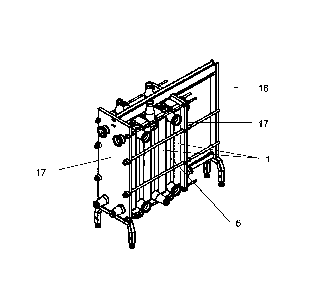
Figure 8 is showing a mixing system having heat exchanger plates 1 and
connection plates 5 within a frame 16. Two end plates 17 are stabilising the
system within frame 16. Different corners are arranged to direct fluids into
or out
of the connection plates and thus add to the multi-function of the mixing
system
of the invention. The mixing system seen in Figure 9 shows connection plates 5
spaced apart within a frame 16. In this figure it can be seen that for
instance
single corners 11 are stopping flows of fluids from one side of a connection
plate or heat exchanger plate 1, and are adding fluid flows from the outside
of
the connection plate or heat exchanger plate into the connection plate or heat
exchanger plate.
Figures 10 to 15 are all schematically presentations of different
possibilities of
mixing internally or externally of the mixing system according to the
invention.
The connection plate in Figure 10 is equipped with single corners 11 for
connecting fluids to an outside source, which could be an external mixing unit
or
could be additional fluids to be treated within a heat exchanger mixing system
of the invention. The connection plate is also equipped with two corners,
which
could be either blind corners 9 or through passage corners 10, or one of each.
CA 02634912 2008-06-23
WO 2007/073281 9 PCT/SE2006/001428
The connection plate in Figure 11 is equipped with an internal mixing element
8.
Figure 12 is showing a connection plate in which one flow of fluids 18 is
directed into a mixing unit or an open space, and another flow of fluids 19 is
directed into the connection plate to an internal temper device to internally
temper flow 18, without mixing flow 18 with flow 19. An external flow of
tempering fluids is led through connections 20, see Figure 13, which
connections 20 may be through passage corners 10. The external flow of
tempering fluids is led into an internal temper device within the connection
plate
having single corners in Figure 13, to temperate fluids in the mixing unit or
the
open space, which may be used as reaction space without mixing. An external
mixing unit 21 is connected to a connection plate in Figure 14 and in Figure
15
is mixing unit 21 equipped with an external temper device 22.
One or more injection ports 23 may be connected to one or more corners or to
one or more sides of a connection plate. In Figure 11 and 12 are injection
port
23 connected to a corner. Figure 13 shows several injection ports 23 connected
along one side of a connection plate. Injection ports 23 may be connected to a
corner which can be seen in Figures 5, 6 or 7.