Note: Descriptions are shown in the official language in which they were submitted.
CA 02635095 2012-02-10
TITLE
HAND-HELD VACUUM PUMP
[0001] Blank
[0002] Blank
[0003] Blank
FIELD OF THE INVENTION
[0004] The present invention generally relates to hand-held vacuum devices,
more
particularly, to hand-held vacuum devices for use in evacuating fluid from
plastic storage
pouches.
BACKGROUND OF THE INVENTION
[0005] Vacuum packaging serves a myriad of purposes ranging from prolonging
food
storage to efficiently using storage space. Numerous vacuum devices are known
including
vacuum pump devices with various drive mechanisms. It is also known to use
vacuum
devices in conjunction with food storage containers and the like to make
vacuum systems.
[0006] One vacuum device has a casing containing an electric motor that
drives a
cylinder piston-unit forming part of a suction pump. The motor is
interconnected with the
cylinder piston-unit via a reducer group including a pinion, a crown gear, and
an eccentric
that actuates a connecting rod attached to the piston.
CA 02635095 2008-06-13
PATENT APPLICATION
Docket No. J-4705
-2-
[0007] A
hand-held suction device has a pump for drawing a vacuum and a motor for
driving the pump. The device further has a vacuum sensor.
[0008]
Another hand-held suction pump for creating a vacuum in a container has a
suction valve, an elongated outer casing, an electric motor, and a piston
pump. The pump
chamber of the piston pump is connected by an inlet valve and a suction duct
to a hollow tip
for coupling to the suction valve of the container and an exhaust duct. The
exhaust duct has a
duct opening in the case for porting exhaust from the pump chamber. A baffle
covers the
exhaust duct.
[0009] Yet
another suction device has a device for removing and storing excess grease
from cooking utensils. The device has a vacuum assembly held within a hollow
housing with
an elongated nozzle. A port sealable with a removable cap provides an access
for removal of
grease held within an internal reservoir of the device.
[0010] Another
hand-held portable apparatus for evacuating storage pouches has a case, a
motor, a fan, and a flange operatively arranged to be coupled with a one-way
valve on a
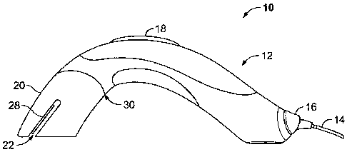
storage pouch. Rechargeable batteries power the motor.
[0011] A container
evacuation system has a storage food container and a vacuum pump.
The container has a housing and a cover with a first non-return valve. The
container
evacuation pump can be driven by an electric drive unit.
[0012] A vacuum
packaging machine has a housing body, a top cover, a thermal sealing
means, a base, and a vacuum generating means is disclosed. The vacuum pressure
generating
means has a drive motor, a crank shaft, and a piston.
[0013] A storage
system has a disposable vacuum pouch with a vacuum valve assembly.
A portable vacuum pump assembly is structured to engage the vacuum valve
assembly, and a
liquid separator assembly is coupled to the portable vacuum pump assembly.
[0014] A combination car cleaner and air pump has a motor and a
transmission consisting
of a worm-gear rod, a worm-gear wheel, and a crank. The motor and transmission
are
connected to a piston and cylinder that draw a vacuum through a hose.
[0015] A vacuum extractor mounted in a one-way valve lid of a vacuum
container has a
motor, a worm, and a worm gear transmission mechanism. The worm gear has an
eccentric
CA 02635095 2008-06-13
PATENT APPLICATION
Docket No. J-4705
-3-
seat and a rod at the eccentric seat to which is pivoted the link that drives
a piston within a
cylindrical casing. A head of the cylindrical casing is fastened to the outer
side of a one-way
valve mounted in a hole in the lid.
[0016]
Another storage system has a disposable vacuum pouch with a vacuum valve
assembly, a portable vacuum pump assembly structured to engage the vacuum
valve
assembly, and a liquid separator assembly coupled to the portable vacuum pump
assembly.
[0017] A
vacuum pump has a suction side and a vacuum conduit in fluid communication
with the vacuum pump suction side. The vacuum conduit has a gas/liquid
separator means.
[0018] One
drive mechanism has a central operating shaft to which a pinion is secured.
The pinion meshes simultaneously with a lower longitudinal toothed edge of a
first rack plate
and an upper longitudinal toothed edge of a second rack plate. Rotation of the
pinion causes
the first rack plate and the second rack plate to reciprocate in opposite
directions.
[0019]
Another drive mechanism has a pinion fixed upon a shaft and a driven element
with an oval rack gear with a wall having an outer contour and a series of
teeth that cooperate
with the pinion. The pinion moves around and follows the contour of the wall
giving the
driven member a vertically reciprocating movement.
[0020] Yet
another drive mechanism has a spur gear engaging a sliding gear with internal
teeth arranged in an oval. The sliding gear is slidable within a yoke via anti-
friction rollers
that contact opposite ends of the yoke. Guide rollers simultaneously traverse
endless guide-
ways causing the sliding gear to always remain in mesh with the teeth of the
spur gear.
[0021] An
additional drive mechanism has a carriage slidably mounted on rods and a
triangular rack gear. A pinion fixed on a first shaft connected to a second
shaft via a
universal joint engages teeth of the rack gear. Rotary motion of the pinion
causes the
carriage to be reciprocated, and the stroke finishes when reciprocatory
movement ceases
while the pinion moves along the base of the triangle.
[0022] Still
another drive mechanism has a geared rod with a base plate upon which are a
central lug and a table that form a loop shaped groove with a rack. A pinion
secured to a
shaft meshes with the rack. Rotation of the pinion causes the base plate to
move in an orbit.
CA 02635095 2013-03-27
PATENT APPLICATION
Docket No. J-4705
-4-
[0023] A further drive mechanism has a drive shaft with a pinion that
drives a driven
element having an oval rack gear. As the pinion turns, the driven element is
moved in a
reciprocatory manner until the pinion reaches a curved portion of the driven
element where
the driven element is rocked and the direction of movement reversed.
[0024] A piston pump has a piston disposed within a cylinder and an oval
rack gear
pivotally mounted to the piston. A drive gear mounted on a drive shaft is
internally adjacent
to the teeth of the oval rack gear. Opposite the piston, the oval rack gear
has a runner that
guides the oval rack gear to cooperatively engage the drive gear.
[0025] A dosing pump unit has a pump unit with a first and a second chamber
and a first
and a second reciprocating piston movable in the respective first and second
chambers,
wherein first and second chambers alternately communicate with inlet and
outlet passages. In
operation, the inlet passage is opened such that, while the first piston is
displaced through a
final portion of a first piston suction stroke and while the second piston is
displaced through
an initial portion of the second piston suction stroke, the inlet passage is
fully open to both
the first and second chambers.
[0026] Another drive mechanism has an actuator with an electric motor and a
transmission that drives an activation element, such as a rotatable arm or a
longitudinally
movable rod. The actuator has a transmission having a first stage that has a
worm gear that
drives a first worm wheel.
[0027] A two-stage reciprocating positive displacement compressor unit has
cooling
means that has at least one first rotary ventilation part driven by a rotary
shaft for generating
a cooling air flow.
SUMMARY OF THE INVENTION
[0028] In one aspect, the present invention provides a hand-held vacuum
device for
evacuating a container, the device includes a housing to hold an electrical
motor operable to drive
a piston pump and a piston valve. The piston pump and the piston valve are
configured to draw a
substantially continuous vacuum during each complete cycle of the piston pump.
The piston
pump comprises a first cylinder having a first piston and a first check-valve
and a second
CA 02635095 2013-03-27
PATENT APPLICATION
Docket No. J-4705
-5-
cylinder having a second piston and a second check-valve. A first piston shaft
eccentrically
connected to a worm gear wheel and the first piston and a second piston shaft
eccentrically
connected to the worm gear wheel and the second piston. The electrical motor
is operatively
connected to a worm gear that drives the worm gear wheel to reciprocate the
first piston and the
second piston within the first cylinder and the second cylinder to draw the
substantially
continuous vacuum. An expansion chamber releasably connected to and in fluid
communication
with the housing and the piston pump. The expansion chamber having a deflector
to alter a fluid
pathway of a fluid before entering an interior volume of the expansion
chamber. A vacuum
interface having a vacuum connecter in fluid communication with the expansion
chamber and
configured to releasably couple to a valve disposed on a container to form an
airtight seal
therewith. The expansion chamber separates air and liquid from the fluid drawn
into the interior
volume of the expansion chamber and collects the liquid therein.
[0029] In another aspect, the present invention provides a vacuum system
that includes a
hand-held vacuum device having a housing including a piston pump that includes
a first cylinder
having a first piston and a first check-valve and a second cylinder having a
second piston and a
second check-valve. The housing further includes an electrical motor
operatively connected to a
worm gear and a worm gear wheel, a first piston shaft eccentrically connected
to the worm gear
wheel and the first piston and a second piston shaft eccentrically connected
to the worm gear
wheel and the second piston. The hand-held vacuum device further includes an
expansion
chamber having an internal reservoir and a vacuum connector capable of forming
a vacuum seal
with a pouch valve. The expansion chamber is releasably secured to the housing
to enable access
to the reservoir and prevents fouling of the piston pump when a vacuum is
drawn through the
vacuum interface. The vacuum system further includes a container having a
valve disposed
thereon to provide fluid communication with the hand-held vacuum device.
[0030] Blank.
CA 02635095 2013-03-27
PATENT APPLICATION
Docket No. J-4705
-6-
BRIEF DESCRIPTION OF THE DRAWINGS
[0031] FIG. 1 is a side elevational view of a vacuum device according to
one
embodiment;
[0032] FIG. 2 is a side elevational view of a vacuum device according to
another
embodiment that can be used on a flat surface;
[0033] FIG. 3 is a trimetric view of the vacuum device of FIG. 2 used in a
hand-held
mode;
[0034] FIG. 4 is a trimetric view of the vacuum device of FIG. 2 used in a
hands-free
mode;
[0035] FIG. 5 is a cross-sectional view of an expansion chamber according
to one
embodiment;
[0036] FIG. 6 is a cross-sectional view of an expansion chamber according
to another
embodiment;
[0037] FIG. 7 is a cross-sectional view of an expansion chamber according
to a further
embodiment;
[0038] FIG. 8 is a trimetric view of a vacuum device according to one
embodiment;
[0039] FIG. 9 is a bottom elevational view of a cross-section of FIG. 8
taken along lines
9-9;
[0040] FIG. 10 is a trimetric view of one embodiment of an expansion
chamber;
[0041] FIG. 11 is cross-sectional view of the expansion chamber of FIG. 10
taken along
lines 11-11;
[0042] FIG. 12 is a trimetric view of one embodiment of vacuum connection
according to
one embodiment;
CA 02635095 2008-06-13
PATENT APPLICATION
Docket No. J-4705
-7-
[0043] FIG.
13 is an elevational view looking end-on to the vacuum connection of FIG.
12;
[0044] FIG.
14 is a perspective view of a vacuum connection according to another
embodiment;
[0045] FIG.
15 is a partially exploded view of a vacuum seal according to one
embodiment;
[0046] FIG.
16 is a partially exploded view of a vacuum device according to another
embodiment;
[0047] FIG. 17 is a side elevational view of a piston pump according to one
embodiment;
[0048] FIG. 18 is a trimetric view of a piston pump according to another
embodiment;
[0049] FIG. 19 is a trimetric view of a piston end cap according to one
embodiment;
[0050] FIG.
20 is a partial cutaway trimetric view of a piston pump according to yet
another embodiment;
[0051] FIG. 21
is a perspective view of a vacuum system according to one embodiment;
[0052] FIG.
22 is a perspective view of a vacuum system according to another
embodiment;
[0053] FIG.
23 is a cross-sectional view of the vacuum system of FIG. 22 taken along
lines 23-23;
[0054] FIG.
24 is a cross-sectional view of the vacuum system of FIG. 22 taken along
lines 24-24; and
[0055] FIG. 25
is a perspective view of a vacuum adaptor according to one embodiment.
[0056] Other
aspects and advantages of the present disclosure will become apparent upon
consideration of the following detailed description, wherein similar
structures have similar
reference numbers.
CA 02635095 2008-06-13
PATENT APPLICATION
Docket No. J-4705
-8-
DETAILED DESCRIPTION
[0057] The
present disclosure is directed to apparatuses such as vacuum pumps that
create a vacuum to evacuate a void volume and/or remove a fluid or a material
from a
container. Illustrative vacuum pumps include, for example, pumps with a single
piston or a
plurality of pistons, such as, for example, two pistons that are configured to
enable a
substantially continuous vacuum to be drawn for each complete cycle of the
piston pump. A
container may include, for example, a sealable plastic container, a storage
pouch with a valve,
a can, a bottle, a hermetically sealable volume, a container with a removable
lid with a valve
associated therewith, and the like, and/or other containers suitable for
vacuum packaging. It
is further contemplated that the vacuum device may be configured to hinder
and/or prevent
the fluid or material removed from the container from entering and fouling the
vacuum pump.
While several specific embodiments are discussed herein, it is understood that
the present
disclosure is to be considered only as an exemplification of the principles of
the invention.
The present disclosure is not intended to limit the disclosure to the
embodiments illustrated.
[0058]
Turning now to the figures, one example of a vacuum device 10 is seen in FIG.
1.
The vacuum device 10 includes a housing 12 that holds a vacuum source (not
shown), such
as a piston pump, though a fan and/or an impeller may be used in lieu of or in
addition to the
piston pump, that is driven by an electric motor (not shown), and an expansion
chamber 20 in
fluid communication with the housing. Illustrated electric motors useful in
the present
disclosure include those disclosed in, for example, Germano U.S. Patent No.
5,195,427.
Other types of motors useful in the present disclosure include AC motors, DC
motors
including shunt-wound, series wound, compound wound, and the like, brushless
motors,
servo motors, brushed DC servo motors, brushless AC servo motors, stepper
motors, linear
motors, and other motors known in the art all of which are commercially
available. The
vacuum device 10 includes an electric cord 14 attached to the housing 12 via a
swivel
connection 16 to power the vacuum source. The vacuum device 10 further
includes a user-
activated switch 18 for activation of the vacuum source. Switches contemplated
for use
herein include, for example, a momentary switch, a timer switch that activates
the vacuum
device 10 for a predetermined amount of time, an attachment-activated switch
that is
activated upon engagement of the vacuum device with a container (not shown),
and/or other
CA 02635095 2008-06-13
PATENT APPLICATION
Docket No. J-4705
-9-
user-activated switches known to those skilled in the art, and combinations
thereof. A
vacuum seal 30 may be positioned between the expansion chamber 20 and the
housing 12 to
provide airtight communication between the vacuum source and a vacuum
interface 22 on the
expansion chamber. The housing 12, expansion chamber 20, and any other
component of the
vacuum device 10 may be made of vacuum resilient and wear and/or use resistant
materials,
including, for example, a plastic, a metal, a rubber, a composite material,
and/or other
materials known to one skilled in the art, as well as combinations thereof.
One or more
components of the vacuum device 10 may also be made of materials that allow
the one or
more components to be submerged in water during cleaning thereof.
[0059] The configurations of the external elements of the vacuum device 10,
including,
for example, the housing 12 and expansion chamber 20, may complement each
other to
enable the vacuum device to be used in a hand-held mode, as well as a hands-
free mode. For
example, a table top and/or surface-mounted vacuum device 100 is depicted in
FIGS. 2-4.
When used as a surface-mounted unit, the vacuum device 10, 100 may be attached
to a work
surface by any means known to one skilled in the art including, for example,
by an adhesive,
a polyolefin plastomer, or one or more suction cups. Further, and as explained
more fully
below, the vacuum device 10, 100 may be configured to insert a portion of a
container 126
therein to assist a user, for example, to align the vacuum device with the
container.
[00601 As seen in FIG. 4, a container, such as a storage pouch 126 having a
valve 131,
may also include an airtight closure mechanism 127 across a mouth of the
storage pouch.
When occluded, the closure mechanism may provide an airtight seal such that a
vacuum may
be maintained in the pouch interior for a desired period of time, such as
days, months, or
years, when the closure mechanism is sealed fully across the mouth. The
closure mechanism
127 may comprise first and second interlocking closure elements that each may
include one
or more interlocking closure profiles (not shown). Further, a sealing material
such as a
polyolefin material or a caulking composition such as silicone grease may be
disposed on or
in the closure elements and closure profiles to fill in any gaps or spaces
therein when
occluded. The ends of the closure elements and closure profiles may also be
welded or
sealed by ultrasonic vibrations as is known in the art. Illustrative closure
profiles, closure
elements, sealing materials, and/or end seals useful in the present invention
include those
CA 02635095 2012-02-10
-10-
disclosed in Pawloski U.S. Patent No. 4,927,474, Tomic et at. U.S. Patent No.
5,655,273,
Sprehe U.S. Patent No. 6,954,969, Kasai et al. U.S. Patent No. 5,689,866,
Ausnit U.S. Patent
No. 6,185,796, Wright et al. U.S. Patent No. 7,041,249, Anderson U.S. Patent
Application
Publication No. 2004/0091179, Pawloski U.S. Patent Application Publication
No. 2004/0234172, Tilman et at. U.S. Patent Application Publication No.
2006/0048483,
Anzini et at. U.S. Patent Application Publication No. 2006/0093242, or Anzini
et al. U.S.
Patent Application Publication No. 2006/0111226. Other closure profiles and
closure
elements useful in the present invention include those disclosed in, for
example, U.S. Patent
No. 7,886,412. It is further appreciated that the closure profiles or closure
elements
disclosed herein may be operated by hand, or a slider may be used to assist in
occluding
and de-occluding the closure profiles and closure elements.
[0061] The
sidewalls I32a, 132b of the container, and/or the closure mechanism 127,
may be formed from thermoplastic resins by known extrusion methods. For
example, the
sidewalls 132a, I32b may be independently extruded of thermoplastic material
as a single
continuous or multi-ply web, and the closure mechanism 127 may be extruded of
the same or
different thermoplastic material(s) separately as continuous lengths or
strands. Illustrative
thermoplastic materials include polypropylene (PP), polyethylene (PE),
metallocene-
polyethylene (mPE), low density polyethylene (LDPE), linear low density
polyethylene
(LLDPE), ultra low density polyethylene (ULDPE), biaxially-oriented
polyethylene
terephthalate (BPET), high density polyethylene (14DPE), polyethylene
terephthalate (PET),
among other polyolefin plastomers and combinations and blends thereof.
Further, the inner
surfaces of the respective sidewalls 132a, 132b or a portion or area thereof
may, for example,
be composed of a polyolefin plastomer such as an AFF1NITYTm resin manufactured
by Dow
Plastics. Such portions or areas include, for example, the area of one or both
of the sidewalls
132a, 132b proximate and parallel to the closure mechanism 127 to provide an
additional
cohesive seal between the sidewalls when the pouch 126 is evacuated of fluid.
The sidewalls
132a, 132b may also be formed of air-impermeable film, such as an ethylene-
vinyl alcohol
copolymer (EVOH) ply adhesively secured between PP and LDPE plies to provide a
multilayer film. Other additives such as colorants, slip agents, and
antioxidants, including for
CA 02635095 2008-06-13
PATENT APPLICATION
Docket No. J-4705
-11-
example talc, oleamide or hydroxyl hydrocinnamate may also be added as
desired. The
closure mechanism 127 may also be extruded primarily of molten PE with various
amounts
of slip component, colorant, and talc additives in a separate process. The
fully formed
closure mechanism 127 may be attached to the pouch body 133 using a strip of
molten
thermoplastic weld material, or by an adhesive known by those skilled in the
art, for example.
Other thermoplastic resins and air-impermeable films useful in the present
invention include
those disclosed in, for example, Tilman et al. U.S. Patent application
publication No
2006/0048483.
[0062] The containers and resealable pouch described herein can be made by
various
techniques known to those skilled in the art including those described in, for
example, Geiger
et at. U.S. Patent No. 4,755,248. Other useful techniques to make a resealable
pouch include
those described in, for example, Zieke et al. U. S. Patent No. 4,741,789.
Additional
techniques to make a resealable pouch include those described in, for example,
Porchia et al.
U.S. Patent No. 5,012,561. Still other techniques to make a container include
those described
in, for example, Zettle et al. U.S. Patent No. 6,032,827 and Stanos et al.
U.S. Patent No.
7063,231. Additional examples of making a resealable pouch as described herein
include, for
example, a cast post applied process, a cast integral process, and/or a blown
process.
[0063] As shown in FIGS. 5-7, the expansion chamber 220 may be designed to
separate
liquids and gases from fluid that enters the expansion chamber to reduce or
prevent fouling of
the vacuum source (not shown) and prolong the useful lifetime of the vacuum
device 10, 100.
The expansion chamber 220 also may help to maintain a clean surface area where
the user is
applying a vacuum to the container (not shown) by collecting a material, for
example, a
liquid, within the expansion chamber. Further, once the liquid has entered the
expansion
chamber 220, the liquid may be prevented from exiting the expansion chamber
until a user
desires to empty the expansion chamber. For example, and now referring to FIG.
5, the
expansion chamber 220 may separate a liquid from a gas, for example, by
altering a fluid
pathway (arrow A) of a vacuum stream taken in through the vacuum interface 222
by way of
a deflector 232, such as an angled tube. The angle of the deflector 232 may
be, for example,
about 100 or greater from horizontal, or about 20 or greater from horizontal,
or about 30 or
greater from horizontal, or about 45 or greater from horizontal, or about 60
or greater from
CA 02635095 2008-06-13
PATENT APPLICATION
Docket No. J-4705
-12-
horizontal, or about 90 or greater from horizontal, or about 90 or lesser
from horizontal, or =
about 1200 or lesser from horizontal, or greater or lesser angles. Not to be
bound by theory, it
is believed that by altering the angle in this way, the fluid entering the
expansion chamber
220 is forced through a tortuous path that slows the velocity of the liquid in
the fluid thus
causing the liquid to fall out of the fluid and be collected in the expansion
chamber. Further,
the deflector 232 may divert the direction of the fluid stream against the
wall of the expansion
chamber 220 to cause the liquid in the fluid to adhere to the wall and thus to
fall into the
expansion chamber. In addition, the deflector 232 may help to inhibit or
prevent leakage of a
material 233, such as a liquid, a solid, or a semi-solid, captured within the
expansion chamber
220 through the vacuum interface 222. In addition, a check valve 234 may be
included on or
in the deflector 232, for example, one an end thereof, that prevents leakage
of liquid through
the vacuum interface 222. The check valve 234 may be any type of valve that
can open in
response to a pressure drop to provide the fluid pathway (arrow A) upon the
activation of the
vacuum device 10, 100 and closes upon deactivation of the vacuum device.
Illustrative check
valves 234 include, for example, a spring-loaded flapper valve, and/or any
other appropriate
valve known in the art.
[0064]
Further, the expansion chamber 20, 120, 220 may be made of opaque and/or
translucent materials and/or may include a transparent window 138, as seen in
FIG. 3,
through which a user may monitor a level and/or amount of material, such as a
liquid, held
within the expansion chamber. It is further contemplated that the expansion
chamber 20,
120, 220 may be graduated to enable a user to determine a volume of material
held within the
expansion chamber. In this way, the user may be able to determine when the
expansion
chamber 20, 120, 220 should be emptied to maintain proper function of the
vacuum device
10, 100. It is further contemplated that the entire expansion chamber 20, 120,
220 be made
from a transparent material to enable monitoring of the level and/or amount of
material held
therewithin. Further, the vacuum device 10, 100 may include one or more
sensors to monitor
vacuum level and/or the level of fluid in the expansion chamber 20, 120, 220
that may
deactivate the electric motor to prevent overheating of the electric motor
and/or overfilling of
the expansion chamber. Further, the one or more sensors may enable the level
of vacuum
being applied to be varied as may be desired for specific uses, such as for
different container
CA 02635095 2008-06-13
PATENT APPLICATION
Docket No. J-4705
-13-
types and/or different food types held within a container. In this way,
operation of the
vacuum device 10, 100 may be more efficient and the lifetime of the vacuum
device may be
extended. One vacuum sensor that may be useful in the present disclosure is
disclosed in, for
example, Kristen U.S. Patent No. 5,765,608. Other suitable vacuum sensors
include those
known in the art.
[0065] In
another embodiment, seen in FIG. 6, liquids 233 may be separated from a fluid
by hindering or slowing the fluid stream, for example, by using a deflector
235 that has an
inner diameter that narrows in the direction of the fluid pathway (arrow A),
such as a
narrowing tube, separately from or in addition to altering the direction of
the vacuum path.
[0066] As
shown in FIG. 7, an embodiment of the expansion chamber 220 includes a
removable mesh screen 236 for the separation of liquids and solids that may be
placed in the
vacuum path upstream of a vacuum pump (not shown). Suitable mesh screens 236
contemplated for use herein may include, for example, a mesh strainer similar
to those used
to prevent debris from clogging a sink drain. The mesh screen 236 may be made
of any
material, such as, for example, stainless steel, plastic, rubber, paper,
fabric, and the like, and
combinations thereof. It is further contemplated that the mesh screen 236 may
be removed
from the expansion chamber 220 for cleaning and/or replacing. Alternatively,
the entire
expansion chamber 220 including the mesh screen 236 may be immersed in water
for
cleaning and/or washed in a dishwasher.
[0067] The
embodiments shown in FIGS. 1-9 include an expansion chamber 20, 120,
220, 320 that has the vacuum interface 22, 122, 222, 322 with a slotted
configuration. The
slotted configuration of the vacuum interface 22, 122, 222, 322 may vary by
angle or any
other desired characteristic, as is seen, for example, in FIG. 1 compared to
FIGS. 2-4 to fit,
for example, various shaped containers and/or valves. As seen in FIGS. 2-4,
the vacuum
interface 122 may be configured to enable a user to place the vacuum device
100 on a flat
surface 124 to accept a container 126 from which a material, such as a fluid
or solid, is to be
evacuated.
[0068]
Further, the slotted configuration of the vacuum interface 22, 122, 222, 322
may
enable, for example, the vacuum device 10, 100, 300 to accept a portion of the
container 126
into the vacuum interface as shown in FIG. 4, such as, for example, a valve
131 disposed near
CA 02635095 2012-02-10
-14-
an edge 129 of the container, which establishes fluid communication between an
interior of
the container and the vacuum device. Illustratively, the valve 131 may be a
check valve or a
one-way valve, to allow air to be evacuated from the container 126 and
maintain a vacuum
when the closure mechanism 127, as previously described herein, has been
sealed.
Illustrative valves useful in the present invention include those disclosed
in, for example,
Newrones et al. U.S. Patent application publication No. 2006/0228057. Any
configurations
of vacuum interface 22, 122, 222, 322 and vacuum connector 28, 128, 228, 328
are
contemplated herein to allow a vacuum connection with the container.
[0069] As shown in FIG. 4, the container 126 may be a collapsible
container, for
example, a plastic pouch, that has a valve 131 on a wall thereof. It is
further contemplated
that a suitable container may include rigid walls and a flexible and/or
elastic component that
collapses as a fluid is drawn from the container, while the rigid walls
maintain their shape. It
is further contemplated that the vacuum interface 22, 122, 222, 322 may be so
configured to
draw a vacuum from the container 126 having more than one valve 131 and/or
aperture (not
shown).
[0070] In the embodiments described herein having a slotted vacuum
interface 22, 122,
222, 322, the vacuum interface may include an oblong and/or oval-shaped o-ring
vacuum
connector 28, 128, 228, 328 in fluid communication with the expansion chamber
20, 120,
220, 320 to releasably couple with the valve 131 and/or other aperture (not
shown) disposed
on the container 126 to form a vacuum seal with the valve and/or other
aperture. Further, the
vacuum connector 328, as shown in FIG. 8, may be disposed within a recessed
channel 329
configured to accept and/or guide a narrow, raised, and elongate valve that
may be, for
example, integrated with and/or associated with a closure mechanism, such as
the valve 2023,
3023 disposed in the closure mechanism shown in FIGS. 21-24, and/or that may
be, for
example, proximal to the side edge of the pouch, as seen in FIG. 4. It is
contemplated in the
embodiments described herein that formation of a vacuum seal between the
vacuum interface
22, 122, 222, 322 and the valve 2023, 3023 (FIGS. 4, 21-24) on the container
126 may cause
CA 02635095 2008-06-13
PATENT APPLICATION
Docket No. J-4705
-15-
one or both of a tactile or audible cue to indicate proper establishment of
the vacuum seal to
ensure efficient evacuation of the container. Further, in this embodiment, the
vacuum device
10, 100, 300 may be associated with the container 126 during evacuation in a
manner similar
to that shown in FIG. 4. It is further contemplated that the oval-shaped ring
vacuum
connector 328 may extend out of the recessed channel 329 below an upper
surface 331 of the
vacuum interface 322. When viewed from below, as is presented in FIG. 9, an
interior
circumference of an aperture 341, which the oval-shaped o-ring vacuum
connector 328
surrounds, is seen to be oval-shaped, as well; however, additional
configurations of the oval-
shaped ring vacuum connector 328 are contemplated herein. As well, the size of
the vacuum
interface 22, 122, 222, 322 may be adjustable, as may be necessary, in order
to accommodate
containers that may vary in thickness.
[0071] In
another embodiment seen in FIGS. 10-13, the vacuum interface 422 may have
an integral, conical shape and/or suction cup-shaped vacuum connector 428 in
place of an
oblong and/or oval-shaped ring vacuum connector to enable a vacuum connection
between
the vacuum device 10 and the valve 131 on the container 126 as shown in FIG. 4
that is
located, for example, on a flat surface of the container. Further, as shown in
FIG. 21, the
cone-shaped vacuum connector 428, for example, may enable evacuation of the
container
2010 having a valve 2024 located in a central portion of a pouch wall 2012.
The valve 2024
may be disposed in or covering an opening (not shown) on a first or second
sidewall 2012,
2014 of the storage pouch 2010 and spaced from the closure mechanism 2022.
Alternatively,
the valve may be disposed in or through the closure mechanism (as seen in
FIGS. 21-24) or in
an opening through a peripheral edge of the pouch not including the mouth (not
shown). The
valve 2024 provides a fluid path with direct fluid communication between an
interior and an
exterior of the pouch.
[0072]
Further, one or both of the pouch sidewalls 132a, 132b may be embossed or
otherwise textured with a pattern, such as a diamond pattern to create flow
channels 2025 on
one or both surfaces spaced between a bottom peripheral edge of the pouch
2020b and the
closure mechanism 2022, or a separate textured and embossed patterned wall
(not shown)
may be used to provide flow channels within an interior of the pouch 2010. The
flow
channels 2025 may provide fluid communication between the pouch interior and
the valve
CA 02635095 2012-02-10
-16-
2024 when fluid is being drawn through the valve. Illustrative flow channels
useful in the
present invention include those disclosed in, for example, Zimmerman et al.,
U.S. Patent
application publication No. 2005/0286808 and Tilman et al. U.S. Patent
application
publication No 2006/0048483.
[0073] In
addition, as seen in FIG. 10, a cone-shaped vacuum connector 428 may be
removably connected to the expansion chamber 420 through, for example, a force-
fit
connection. In another embodiment, a release mechanism 430 may releasably
secure the
cone-shaped vacuum connector 428 to the expansion chamber 420, as is seen in
FIG. 11.
Further, as shown in FIGS. 12 and 13, the cone-shaped vacuum connector 428 may
have an
aperture 441 with an elliptical configuration, such that the length X of the
mouth is greater
than the width Y of the mouth.
[0074] In
yet another embodiment seen in FIG. 14, a cone-shaped vacuum connector 528
is connected to or conjoined with a rectangular portion 590 that includes an
aperture 510.
The rectangular portion 590 is configured to fit into the slotted vacuum
interface 22, 122,
222, 322 described above such that the vacuum interface having a slotted
interface may be
reversibly adapted to hold the cone-shaped vacuum connector 528. It is further
contemplated
that the rectangular portion 590 and the slotted vacuum interface 22, 122,
222, 322 may be
configured suc,h that when the rectangular portion is fitted into the slotted
vacuum interface, a
tactile cue and/or an audible cue may indicate when a vacuum connection has
been
established between the cone-shaped vacuum connector 528 and the expansion
chamber 20,
120, 220, 320, as discussed below.
[0075] In
one embodiment, seen in FIG. 15, the expansion chamber 620 is connected
releasably to the housing 612 by a vacuum seal 630. The vacuum seal 630 may
include a
connection such as an o-ring 640 on an end portion 641 of the expansion
chamber 620 and/or
on an end portion 642 of the housing 612 in combination with a quick release
mechanism 644
that includes a channel or groove 646 and a complementary raised portion 648.
The groove
646 and raised portion 648 maybe located on either the expansion chamber 620
and/or the
end portion 642 of the housing 612 or both. In this way, to remove the
expansion chamber
CA 02635095 2008-06-13
PATENT APPLICATION
Docket No. J-4705
-17-
620 from the housing 612, for example, to empty out and/or clean the expansion
chamber, a
user may twist the expansion chamber relative to the housing to interrupt the
vacuum seal
630 and thereby release the expansion chamber from the housing. The expansion
chamber
620 may then be evacuated and cleaned via the end portion 641 rather than
being evacuated
through the vacuum interface 622. To reestablish a vacuum connection between
the
expansion chamber 620 and the housing 612, a user may reverse the steps needed
for
disassembly of the vacuum device (not shown). Additional connection ways are
contemplated herein for joining the expansion chamber 620 and housing 612 of
contemplated
vacuum devices as are known to one skilled in the art such as male and female
threads or an
interference fit arrangement.
[0076] In
another 'embodiment seen in FIG. 16, the housing 712 may further include a
vacuum port 743 that may protrude from the end of the housing to be connected
to the
expansion chamber 720. The vacuum port 743 provides access to the expansion
chamber 720
for a vacuum source (not shown) and is an extension of a vacuum tube (not
shown)
connecting the vacuum source to the expansion chamber. When the housing 712
and
expansion chamber 720 are joined, the stem 743 may extend into the expansion
chamber to
hinder intake of material into the housing and/or vacuum source from the
expansion chamber.
It is further contemplated that a cap 745 may be included on the end of the
stem 743 to
further aid in protecting the housing interior and vacuum source from
materials taken into the
expansion chamber 720 during use of the vacuum device 710. The cap 745 may be
a valve, a
filter, a sensor, an adaptor to allow additional accessories to be added to
and/or in the stem
and/or expansion chamber 720 and/or have any desirable shape. It is further
contemplated
that the cap 745 may reduce the size of the stem aperture, change the
direction of vacuum
path, and extend the length of the stem.
[0077]
Illustrative vacuum pumps useful in the present disclosure include those shown
in
FIGS. 17, 18, and 20. As described more fully below, vacuum pumps may be
piston pumps
that include one or more cylinders containing one or more pistons. The pistons
may be
conventional single-action pistons that take in air through a valve during an
upstroke or a
down stroke and releasing the air through a separate valve during a down
stroke or an
upstroke to complete a single cycle. It is further contemplated herein, that a
piston pump may
CA 02635095 2008-06-13
PATENT APPLICATION
Docket No. J-4705
-18-
incorporate a dual-action piston that pumps air during both upstrokes and down
strokes via a
system of valves, on both ends of a single cylinder. Vacuum pumps of the
present disclosure
may be driven by an electric motor powered by one or more batteries, an
external electric
cord, other sources known in the art, and any desirable combination thereof.
The batteries
may be removable for replacement and/or rechargeable. The electric motor may
be
operatively connected to the vacuum pump via a gearing system that translates
rotary motion
into rectilinear motion to enable a piston to reciprocate within a cylinder.
[0078] In
the embodiments shown in FIGS. 17, 18, and 20, the piston pumps 800, 900,
1000 may be configured to draw a substantially continuous vacuum for each
complete cycle.
For example, one half of a complete cycle for a double or dual piston vacuum
pump 800,
1000, as shown in FIGS. 17 and 20, may include a first piston 862a, 1002a that
draws air into
a first cylinder 864a, 1028a while a second piston 862b, 1002b exhausts air
from a second
cylinder 864b, 1028b. During the second half of the cycle, the second piston
862b, 1002b
draws air and the first piston 862a, 1002a exhausts air from their respective
cylinders 864a,
1028a. Valving (not shown) associated with the first 864a, 1028a and second
cylinder 864b,
10286 may alternately draw air through the vacuum port 743 (seen in FIG. 16)
in fluid
connection the expansion chamber 20, 120, 220, 320 in correspondence with the
draw phases
of the first and second cylinders, as known by those skilled in the art. In
this way, at
substantially all times during the cycle the vacuum pump 800, 1000 is drawing
a vacuum, and
thus providing a substantially continuous vacuum. The first 864a, 1028a and
second 864b,
1028b cylinders may include valves (not shown) to enable a unidirectional flow
of air into the
cylinder through a first valve 866a, 866b and out through a second valve 867a,
867b.
Further, the first 862a, 1002a and second 862b, 1002b pistons may be exactly
out of phase
(about 180 ) such that as the first piston completes an upstroke, the second
piston would
complete a down stroke. As an alternative, the first 862a, 1002a and second
862b, 1002b
piston may be off being about 180 out of phase, such that as the first piston
begins an
upstroke before the second piston would complete a down stroke. In this way, a
substantially
continuous vacuum may be drawn by the vacuum pump 800, 1000. In the case of a
dual-
action piston 962 as described above, a complete cycle may include one
upstroke and one
CA 02635095 2008-06-13
PATENT APPLICATION
Docket No. J-4705
-19-
down stroke, during each of which the piston alternately draws air and
exhausts air on
opposite sides of the piston head.
[0079]
Drawing a substantially continuous vacuum may enable a more linear and
potentially faster decrease in pressure from a container being evacuated
compared to a
standard vacuum device with a conventional single piston that provides a
pulsed or stepped
decrease in pressure due to a requisite lag phase that follows each draw
phase, for example, a
drawing upstroke would be followed by an exhausting down stroke. Substantially
continuous
vacuum piston pumps minimize such a lag phase and may thus potentiate a more
efficient
and/or faster evacuation of a container from which a material is being
extracted.
Substantially continuous vacuum piston pumps may also use less energy to
evacuate certain
containers. For example, a container with a valve that utilizes a tacky or an
adhesive sealing
method may be evacuated more efficiently using a substantially continuous
vacuum piston
pump because the valve would remain open throughout the evacuation rather than
closing
intermittently during drops in or plateauing of pressure during lag phases of
a conventional
piston pump. In addition, greater efficiency associated with substantially
continuous vacuum
piston pumps leads to a more efficient motor use that may extend motor and/or
battery life
and/or conserve electricity.
[0080]
Illustratively for a hand-held vacuum device including those shown in FIGS. 1-
4,
8, and 16 for use in a typical household situation to evacuate a one gallon or
less container, a
vacuum drawn by a piston pump 800, 900, 1000 of the present disclosure through
the
expansion chamber 20, 120, 320, 720 may range, for example, from about 3 to
about 30 in.
Hg, or from about 4 to about 20 in. Hg, or from about 12 to about 25 in. Elg.
As well, a
piston pump 800, 900, 1000 of the present disclosure may generate a flow rate
through the
expansion chamber 20, 120, 320, 720 of about 0.15 to about 1.5 cfm or from
about 0.5 to
about 0.75 cfm. It is contemplated that greater and lesser ranges may be
achieved by piston
pumps 800, 900, 1000 of the present disclosure depending on the size and
configuration of
the piston pumps and drive mechanisms, and/or the intended use of the vacuum
device.
[0081] Referring
now to FIG. 17, a dual piston pump 800 includes an electric motor 852
having a motor shaft 854 with a motor gear 856, such as, for example, a pinion
or a worm
gear on one end thereof. Illustratively, the motor gear 856 may be attached to
the motor shaft
CA 02635095 2008-06-13
PATENT APPLICATION
Docket No. J-4705
-20-
854 by a screw mount 858. One or more gears 860 or one or more gearing systems
may also
be directly or indirectly enmeshed with the motor gear 856 to translate the
rotary motion of
the motor gear into rectilinear motion to enable a piston 862a, 862b to
reciprocate within a
cylinder 864a, 864b. Examples of suitable gears include, for example, a crown
gear and/or a
worm-gear wheel. For example, in FIG. 17, the motor gear 856 is a worm gear
that is
enmeshed with a worm-gear wheel 860 that has an axis of rotation (arrow B) at
or
approaching about 90 degrees to the axis of rotation of the motor shaft 854.
Describing one
side of the dual piston pump 850, which may be either side, reciprocatory
motion may be
imparted to the piston 862a within the cylinder 864a that has a check-valve
866 or other valve
on one end thereof by the worm-gear wheel 860 via an eccentrically placed pin
868 to which
a piston rod 870 is operatively attached to the piston. The piston rod 870a
may be rigidly
attached to the piston 862a, or alternatively, the piston rod may be pivotally
attached to the
piston.
[0082] By varying the point of attachment of the piston rod 870a, 870 lb on
the worm-
gear wheel 860, the piston stroke length, number of strokes per minute, and
phase of the first
and second piston with respect to each other may be adjusted accordingly at a
given number
of revolutions by the electric motor 852. Alternatively or in addition to
altering placement of
the pin 868 to achieve the above-mentioned variations, the motor gear 856 may
be enmeshed
with a transmission (not shown) that includes one or more gears to increase or
decrease the
power provided by the electric motor 852 to the piston 862a, 862b. Additional
gear sizes as
well as different gearing systems, for example, that incorporate a belt, a
pulley, a chain, or a
combination thereof are contemplated for driving piston pumps contemplated
herein.
[0083] Referring now to FIG. 18, a dual-action piston pump 900 according to
one
embodiment is shown. The dual-action piston pump 900 draws and pushes air on
each
upstroke and each down-stroke of a single piston 962. The dual-action piston
pump 900
includes an electric motor 952, a motor shaft 954, a motor gear 956, and a
worm-gear wheel
960 with an eccentrically placed pin 968 similar to that of the dual piston
pump 950 described
above. A single cylinder 964 houses the piston 962 that is rigidly connected
to a piston rod
970. In the embodiment shown, the piston rod 970 has a bracket 972 located
opposite of the
piston 962. The bracket 972 has slot 974 disposed therein that accepts the pin
968 of the
CA 02635095 2008-06-13
PATENT APPLICATION
Docket No. J-4705
-21-
worm-gear wheel 960. During operation, the worm-gear wheel 960 revolves
causing the pin
968 to reciprocate within the slot 974 of the=bracket 972, and in so doing,
the piston rod 970
and piston 962 are reciprocated within the cylinder 964.
[0084] The cylinder 964 further includes a cylinder end cap 976 on both
ends thereof.
The cylinder end cap 976, as shown in FIG. 19, has a pair of one-way valves
978a, 978b and
as shown, an aperture 980 for passage of the piston rod 970. The cylinder end
cap 976
opposite the motor may lack an aperture 980 or the aperture may be plugged
using suitable
means known to one skilled in the art. The cylinder end caps 976 present on
opposite ends of
the cylinder 964 of the dual-action pump 900 enable air to be drawn into the
cylinder on one
side of the piston 962 when the piston moves in one direction while air is
pushed out of the
cylinder on the opposite side of the piston.
[0085] FIG. 20 presents another embodiment contemplated herein that
includes a dual
piston pump 1000, though a configuration including one or two dual-action
pistons is
contemplated, as well. In the illustrated embodiment, two pistons 1002a, 1002b
share a
central axis (arrow C) and are rigidly attached to opposite ends of an oval
rack gear 1004. An
electric motor 1006 includes a drive shaft 1008 to which a motor gear 1010 is
attached. A
planetary gear 1012 is enmeshed with the motor gear 1010 and the oval rack
gear 1004. The
planetary gear 1012 is carried by an L-arm 1014 via a pin 1016 that extends
through the
planetary gear and beyond a lower side of the planetary gear to travel within
an interior track
1018 of the oval rack gear 1004 as the oval rack gear reciprocates upon
activation of the
electric motor 1006. Further, the L-arm 1014 is pivotally secured to an end of
the drive shaft
1008 above the motor gear 1010 and includes a guide pin 1020 that engages an
exterior side
surface 1022 of the oval rack gear 1004. In this way, the L-arm 1014 holds the
planetary gear
1012 within the interior track 1018 and stationary against straight sections
1024 of the oval
rack gear 1004 and allows the planetary gear to orbit around the motor gear
1010 at the
curved end sections 1026 of the oval rack gear, thereby reciprocating the oval
rack gear along
a path parallel to the axis (arrow C) of the pistons 1002a,= 1002b within
opposing cylinders
1028a, 1028b, which are shown in cross-section for clarity.
[0086] FIG. 21 presents a vacuum system 2000 according to one embodiment.
The
vacuum system 2000 includes a resealable pouch 2010 having a first sidewall
2012 and a
CA 02635095 2008-06-13
PATENT APPLICATION
Docket No. J-4705
-22-
second sidewall 2014 that are connected, such as by folding, heat seal, and/or
adhesive, along
three peripheral edges 2020a, 2020b, and 2020c to define an interior space
2016
therebetween and an opening 2018 along a top edge 2020 where the first and
second
sidewalls 2012, 2014 are not connected so as to allow access to the interior
space 2016. A
resealable elongate closure mechanism 2022 along the first and second
sidewalls 2012, 2014
near the opening 2018 extends between the peripheral edge 2020a and the
peripheral edge
2020c of the pouch 2010 to allow the opening 2018 to be repeatedly occluded
and
deoccluded, thereby sealing and unsealing, respectively, the opening 2018.
Protuberances,
such as ridges 2056, may be disposed near the opening 2018 to provide
increased traction in a
convenient area for a user to grip, such as a gripping flange, when trying to
open a sealed
pouch.
[0087] When
occluded, the closure mechanism 2022 provides an airtight seal such that a
vacuum may be maintained in the pouch interior 2016 for a desired period of
time, such as
days, months, or years, when the closure mechanism is sealed fully across the
opening 2018.
In one embodiment, the pouch 2010 may include a second opening 2018a through
one of the
sidewalls 2012, 2014 covered by a valve 2024, such as a check or one-way
valve, to allow air
to be evacuated from the pouch interior 2016 and maintain a vacuum when the
closure
mechanism 2022 has been sealed. As shown in FIG. 21, the valve 2024 may be
disposed on
the first sidewall 2012 spaced from the closure mechanism 2022. The valve 2024
provides a
fluid path with direct fluid communication between the pouch interior 2016 and
an exterior
2216 of the pouch 2100.
[0088] The closure
mechanism 2022 includes a first closure element 2026 that releasably
interlocks and seals with an opposing second closure element 2028. Each of the
closure
elements 2026, 2028 has a substantially constant elongate cross-sectional
profile that extends
longitudinally between the peripheral edge 2020a and the peripheral edge 2020c
of the pouch
2010 to form a continuous seal therealong when fully interlocked with the
opposing closure
element. In one embodiment, the first closure element 2026 is disposed on an
interior surface
2034 of the second sidewall 2014 and the second closure element 2028 is
disposed along an
exterior surface 2036 of the first sidewall 2012. In other embodiments, the
orientation of the
CA 02635095 2008-06-13
PATENT APPLICATION
Docket No. J-4705
-23-
closure elements 2026, 2028 with respect to the sidewalls 2012, 2014 may be
reversed
accordingly.
[0089] The
vacuum system 2000 further includes a vacuum device 2100 similar to those
described above to evacuate fluid from the pouch 2010 through, for example,
the valve 2024
disposed in one of the side walls 2012, 2014. The vacuum device 2100 includes
a housing
2112 that holds a vacuum source (not shown) and an expansion chamber 2120 in
fluid
communication with the housing. The vacuum device 2100 includes an electric
cord 2114
attached to the housing 2112 via a swivel connection 2116 to power the vacuum
source. The
vacuum device 2100 further includes a user-activated switch 2118 for
activation of the
vacuum source. A vacuum interface 2122 includes an integral, conical shape
and/or suction
cup-shaped vacuum connector 2128 to enable a vacuum connection between the
vacuum
device 2100 and the valve 2024 on the pouch 2010.
[0090] FIG.
22 illustrates another embodiment of a vacuum system 3000 with the
resealable pouch 3010 and the vacuum device 3100 in vacuum communication. The
resealable pouch 3010 has a first sidewall 3012 and an opposing second
sidewall 3014
connected along three peripheral edges 3020a, 3020b, and 3020c to define an
interior space
(not shown) therebetween and an opening (not shown) along a top edge 3020
where the first
and second sidewalls 3012, 3014 are not connected so as to allow access to the
interior space
3016. A resealable elongate closure mechanism 3022 along the first and second
sidewalls
3012, 3014 near the opening 3018 extends between the peripheral edge 3020a and
the
peripheral edge 3020c of the pouch 3010 to allow the opening to be repeatedly
occluded and
deoccluded, thereby sealing and unsealing, respectively, the opening. Internal
and external
elements of the closure mechanism 3022 (discussed below in reference to FIG.
24) form a
valve 3023 that enables a slotted vacuum interface 3122 to form a vacuum
connection with
the pouch 3010.
[0091] The
vacuum device 3100 includes a housing 3112 that holds a suitable vacuum
source and an expansion chamber 3120 in fluid communication with the housing
to which an
electric cord 3114 is attached via a swivel connection 3116 to power the
vacuum source. A
user-activated switch 3118 can be used to activate the vacuum source. A vacuum
interface
3122 has a slotted configuration, similar to those described above, to enable
a vacuum
CA 02635095 2008-06-13
PATENT APPLICATION
Docket No. J-4705
-24-
connection between the vacuum device 3100 and the pouch 3010 to be established
upon
guiding the closure mechanism 3022 and the valve 3023 into a recessed channel
3329 (seen
in FIG. 24) of the vacuum interface. In a manner similar to that depicted in
FIG. 4, the pouch
3010 and the vacuum device 3100 may be in interlockingly engaged via the valve
3023 with
the vacuum interface 3122 to enable fluid to be drawn through apertures 3082
in the closure
element 3028 disposed on the exterior surface 3036 of the sidewall 3012 and
into the
expansion chamber 3120 of the vacuum device 3100. In the embodiment shown, the
vacuum
system 3000 is configured for both hand-held and hands-free operation.
[0092]
Proper alignment and establishment of a vacuum connection between the valve
3023 and a vacuum connector 3328 (seen in FIG. 24) disposed within the
recessed channel
3329 may be indicated by an audible and/or tactile cue. As shown in cross-
section generally'
along lines 23-23 of FIG. 22 (and along post 3042b of FIG. 24, see below),
FIG. 23 depicts
the valve 3023 inserted into the recessed channel 3329 of the expansion
chamber 3120 to
enable, for example, a spring-loaded button 3402 attached to a spring 3404
secured to the
expansion chamber to snap into a depression 3406 in the closure element 3028
with sufficient
force to create an audible and/or tactile cue. Other snap-fit connection
mechanisms known to
one skilled in the art are also contemplated for inclusion herein. The spring-
loaded button
3402, depression 3406, and vacuum connection 3328 are configured so that
concomitant with
the audible and/or tactile cue, a vacuum connection is established between one
or more
apertures 3082 associated with the valve 3023 and the internal volume of the
expansion
chamber 3120 via the vacuum connector. Thus established, the vacuum connection
allows
fluid to be drawn from the pouch 3010 into the expansion chamber 3120, where
liquids 3233
or other materials may be held.
[0093] An
enlarged partial cross-section generally along lines 24-24 of the interlocking
engagement of the closure mechanism 3022 with the vacuum interface 3122 of the
vacuum
system of FIG. 22 is shown in FIG. 24. This figure illustrates a vacuum
connection between
the valve 3023 and the vacuum connector 3328 of the expansion chamber and the
extraction
of fluid 3233 (depicted from arrows) from an interior side 3048 of the closure
elements or
profiles 3026, 3028 of the pouch 3010.
CA 02635095 2008-06-13
PATENT APPLICATION
Docket No. J-4705
-25-
[0094] For
clarity, the following description of one contemplated embodiment for the
valve 3023 within the closure mechanism refers only to one portion of the
valve within the
closure mechanism during the application of a vacuum by the vacuum device
3100, where a
vacuum connection has been established between the pouch 3010 and the vacuum
device.
This description applies similarly to the remainder of the closure mechanism
3022 as
indicated by the curved arrows. Induction of a vacuum by the vacuum device
3100 draws
fluid from the interior of the pouch 3010 past a cantilevered flap 3080
extending from a
flange 3074 toward a post 3042a with an arrow-shaped head 3052 disposed
thereon. The
fluid is then drawn into a channel 3060 formed between an exterior leg 3066a
and the post
3042a and out of the pouch 3010 through apertures 3082 disposed on an end of
the closure
element 3028 and aligned with a space 3342 between the closure element and an
aperture
(not shown) leading into a deflector 3235 of the expansion chamber 3120.
[0095] Another
embodiment contemplated herein is shown in FIG-25, in which a
vacuum adaptor
4528 includes a cone-shaped vacuum connector 4428 connected to or =
conjoined with a docking portion 4590 configured to fit into the slotted
vacuum interface 22,
122, 222, 322, 622, 2122, 3122 of the expansion chamber 20, 120, 220, 320,
620, 2120,3120.
Upon insertion of the docking portion 4590 into the vacuum interface 22, 122,
222, 322, 622,
2122, 3122, a spring-loaded button 3402 (see FIG. 23) or similar device snaps
into a
depression 4406 to produce an audible and/or tactile cue to indicate
establishment of a
vacuum connection between an aperture 510 in the docking portion 4590 and the
interior
volume of the expansion chamber 20, 120, 220, 320, 620, 2120, 3120. In this
way, the
vacuum interface 22, 122, 222, 322, 622, 2122, 3122 may be reversibly fit with
a cone-
shaped vacuum connector 4428. In addition to the above described, additional
lock and key
configurations known to one skilled on the art that produce an audible and/or
tactile cue to
indicate establishment of a vacuum connection are contemplated herein.
CA 02635095 2012-02-10
-26-
INDUSTRIAL APPLICABILITY
[0096] The present disclosure provides a vacuum device that enables the
evacuation of
storage containers, such as a vacuum storage pouch, through valves on the
containers.
Expansion chambers separate materials evacuated from the containers to protect
vacuum
sources and prolong usage of the vacuum devices. The piston pumps utilized
herein may also
provide an efficient vacuum source by providing a substantially continuous
vacuum.
[0097] Numerous modifications will be apparent to those skilled in the art
in view of the
foregoing description. Accordingly, this description is to be construed as
illustrative only and
is presented for the purpose of enabling those skilled in the art to make and
use the disclosure
and to teach the best mode of carrying out same. The exclusive rights to all
modifications
within the scope of the impending claims are reserved.