Note: Descriptions are shown in the official language in which they were submitted.
CA 02635191 2008-06-17
WATER CHUTE
The invention relates to a water chute having a chute
emerging in an outlet, the said chute comprising a
starting stretch and a finishing stretch, which latter
emerges in the outlet.
The demands placed upon attractions in leisure parks
are steadily rising. Thus, in water parks or adventure
parks, for example, water chutes are offered, which are
configured as black hole chutes, as wide chutes and as
high-speed water chutes. Furthermore, a water chute
comprising a jump has already been developed, which is
known from DE 201 20 561 Ul.
US 2004/0198520 Al discloses a water chute formed by
two rectilinearly running track portions, which are
arranged at an acute angle to each other and merge
together at a common point. Starting from a starting
stretch, the end of the first rectilinear run leads
into the beginning of the second rectilinear run, which
passes at the end into a finishing stretch. In this
water chute, the run is configured as a type of
zigzagging chute. After the user has left the starting
stretch, an upwardly directed sliding movement is made.
In the transition region from the first to the second
run, the sliding speed is reduced to zero, so that the
rider is sent into a fresh acceleration phase in the
opposite sliding direction. A so-called loop ride is
hence not enabled.
In addition, a water chute has been disclosed which has
a very long and steep starting stretch, which passes
into a loop section, the starting point of the loop and
the end of the loop lying directly adjacent to each
other and aligning the loop section in the vertical
direction. A loop chute of this kind has the drawback
that the generated accelerations are too high and the
CA 02635191 2008-06-17
- 2 -
users suffer injuries to the neck and vertebral region
and also briefly experience considerable balance
disorders after using the loop chute. The design of a
loop section as a loop without the aforesaid drawbacks
could, however, considerably enhance the nature of the
experience.
The object of the invention is therefore to provide a
water chute having a chute emerging into an outlet,
which chute comprises a loop section which allows
upside-down sliding and in which the loads upon the
human body lie below the maximally permitted
acceleration force of a standard drawn up for water
chutes.
This object is achieved according to the invention by
the features of Claim 1. Further advantageous
embodiments and refinements of the invention are
defined in the other claims.
The inventive design of the water chute has a loop
section which, viewed from a starting point of the loop
section, comprises at least one circumferential angle
of at least 270 and which, at least between a starting
point and a summit of the loop section, is inclined by
at least 20 to 80 relative to a vertical or has a
transverse inclination. As a result of the alignment of
the loop section, which alignment is provided outside a
vertical, the maximum acceleration at the transition
from the starting point into the rising section portion
of the loop section can be reduced, so that the loads
arising from the acceleration and centrifugal forces do
not lead to any physical impairments in the user. In
order to reduce the physical loads, the angle of
inclination of the loop section relative to the
vertical can be enlarged, the sensation of upside-down
travel being able to be imparted to the user even if
the angle of inclination relative to the vertical is
very large. In addition, this arrangement has the
CA 02635191 2008-06-17
- 3 -
advantage that, whilst the length of the starting
stretch remains constant, use by both light and heavy
persons is made possible. The inclined arrangement also
makes it possible for slower-sliding users or very
light users to experience, instead of upside-down
travel, a type of roller coaster ride.
An alternative embodiment of the water chute is given
by the fact that the loop section has a crossover point
and the loop section is inclined by at least 5 to 80
relative to a vertical. The initial and finishing
stretches, adjoining the rising and falling sections of
the loop section, can be aligned in different
directions, so that a flexible chute course is enabled.
According to a further preferred embodiment of the
invention, it is provided that the radius of curvature
of the loop section, starting from the starting point
of the loop section to the summit of the loop section,
diminishes. The starting point of the loop section
preferably constitutes the transition from a falling
course of the starting stretch into a rising course of
the loop section. Following this, the radius of
curvature of the loop section declines, so that the
gravity-induced reduction of the sliding speed is
compensated by a reduction in the radius of the loop
section up to the summit so as not to reduce the
centrifugal force, or reduce it only by a small amount,
so that the summit is slid through or passed through at
the necessary minimum speed. It is preferably provided
that the reduction in radius of the loop section leads
to a constant centrifugal force acceleration, which is
preferably less than or equal to the permitted
acceleration.
According to a first alternative embodiment, it is
provided that the radius of curvature between the
starting point and the summit of the loop section is
continually reduced. The loop section is made up of a
CA 02635191 2008-06-17
- 4 -
plurality of individual track segments. These are
matched, in accordance with the size of the circular
arc segment, to the reduction in the radius of
curvature. Such a design produces a very uniform curve
acceleration.
According to an alternative embodiment of the
invention, it is provided that the radius of curvature
between the starting point and the summit of the loop
section is reduced portion by portion. The portion-by-
portion reduction in the radius of curvature is
realized from track segment to track segment of which
the loop section is composed. A simple manufacture of
the individual track segments can thereby be obtained,
since these have a constant radius over their angular
range. A manufacture based on identical parts for the
section between the starting point and the summit, on
the one hand, and from the summit to the finishing
point, on the other hand, can hence also be obtained.
Preferably, for a run from the starting point up to the
summit, a radius of curvature is provided which is
formed from a combination of a run for a circular loop
and a clothoid loop. This ensures that a uniform curve
acceleration for the user is obtained, the centrifugal
accelerations which are here in force being less than
or equal to the permitted accelerations. For example,
the combination of the two loop shapes can lead to a
considerable reduction in the high accelerations
generated directly after the starting point in a
circular loop and to an increase in the excessively low
accelerations generated in a pure clothoid loop, for
example at a 90 , 135 , 180 and 225 angle, so that a
centrifugal force of greater than or equal to 1 g
[m/sz] acts upon the user and a lifting of the user
from the sliding surface is prevented, in some track
portions a centrifugal force of less than 1 g being
non-critical provided that the sliding acceleration is
sufficiently high.
CA 02635191 2008-06-17
- 5 -
According to a further preferred embodiment, it is
provided that the loop section from the summit to the
finishing point is configured inversely to the run from
the starting point to the summit. Hence, not only can a
simple construction be obtained by virtue of identical
parts, but also identical curve accelerations can be
given for each sector within the loop section, which
provide an improved sliding sensation for the user.
In order to reduce the acceleration forces during
sliding in the loop section, the run from a track bed
in the summit to the starting point of the loop section
comprises a minimum radius of 2 m. It can thereby be
ensured that no excessive accelerations are generated
which would result in injuries to the user.
According to a further preferred embodiment of the
invention, it is provided that the chute, at least
along the loop section, is fully closed. A safe loop
section having an upside-down running chute can hence
be created. This closed arrangement of the loop section
can be made from various materials. For example, a
part-circumference of the tubular loop section can be
fully transparent. Furthermore, tube segments can also
be provided which let daylight through but do not
permit a view of the surroundings.
A further preferred embodiment of the water chute
provides that the chute, viewed in cross section, is of
circular configuration. This enables constant
conditions to be created for persons of different
weight to pass through the loop section.
A further alternative embodiment for the geometric
design of the sliding surface provides that the chute
comprises a sliding surface having a profile which is
designed to guide the riders. Based on, for example, a
circular cross section of the chute, lateral guide
CA 02635191 2008-06-17
- 6 -
profiles can be applied to the sliding surface, so that
the slide path is predefined. Hence, high sliding
speeds can be obtained and undesirable rocking motions
of the rider can be prevented. As an alternative to the
guide profiles, which are applied to the sliding
surface or are built into it, the guide profile can be
configured by a recess in the sliding surface, which is
superimposed on the circular cross section of the
chute. The same effect can thereby be obtained. Lateral
guide profiles of this kind can be provided in portions
or fully along a chute. The lateral guide profiles can
also be used and adapted for other cross sections of
the chutes differing from the circular cross section.
According to a further alternative embodiment of the
invention, it can be provided that a sliding surface of
the chute, viewed in cross section, has a trough-shaped
recess. The rider can hence be fully guided whilst
sliding down the water chute. Preferably, the trough-
shaped recess in the loop section is designed such that
the lowest point of the trough-shaped recess lies
within the direction vector of the maximally acting
acceleration force of a rider.
According to a further alternative embodiment, it is
provided that a sliding surface of the chute, viewed in
cross section, has a rectilinearly running sliding
surface, which is laterally adjoined, for the
limitation of the sliding surface, by lateral guide
walls. An alternative embodiment of this kind allows,
for example, two persons to slide through a loop
section side by side.
Preferably, the sliding surface of the chute is
subjected at least partially along the loop section to
a water film, water fall or spray mist, so that, over
the whole of the chute, in particular the upside-down
region of the loop section, a liquid slide film is also
maintained.
CA 02635191 2008-06-17
- 7 -
To prevent water from collecting at the starting point
of the loop section, a water run-off region is
preferably integrated in the sliding surface. This
water run-off region can be configured in a grille
shape or slot shape by virtue of narrow openings and
can pass flush into the sliding surface.
At the starting point of the loop section, an escape
section is preferably provided. This escape section is
not configured as a closed tube, but rather, for
example, as a half shell, or, in the case of a closed
tube, has at least one escape opening outside the
sliding surface. This allows an escape facility to be
provided for persons who have failed to reach the
necessary climbing height up to the summit and who
slide back to the starting point of the loop section.
In addition, it is preferably provided that a loop or
angle of radius of a following loop section is
configured smaller than that of the preceding loop
section. This ensures that a sufficient speed of the
rider to slide through the second or further following
loop section continues to be present.
In addition, it is preferably provided that an angle of
inclination of a following loop section is configured
larger than that of the preceding loop section in
relation to the vertical.
As a result of the increasingly shallow angle of
inclination, the one or more following loop sections
can be passed through at reduced sliding speeds without
the loop effect being lost to the user.
In addition, it is preferably provided that a first
loop section and at least one following loop section
are inversely inclined relative to the vertical. As a
result of such a V-shaped alignment of at least two
CA 02635191 2008-06-17
- 8 -
consecutive loop sections, an increased thrill can be
provided by a further change of direction.
Alternatively, it can be provided that two or more loop
sections are preferably inclined at the same angle
relative to the vertical.
According to a further preferred embodiment, it is
provided that, for example, a first loop section
comprises a lower summit than a following loop section.
Hence different sliding speeds can be obtained and thus
the thrill increased.
For the monitoring of the water chute having at least
one loop section, it is preferably provided that at the
summit of the loop section or at the end of the
finishing stretch there is provided at least one
monitoring sensor, which controls a chute clearance
signalling device provided at the entrance. A
controlled and monitored water chute can hence be
produced, which monitors the hidden regions of the
water chute.
According to a preferred embodiment of the invention,
it is provided that a rising and a falling section of
the loop section are inclined within a common angular
range to the vertical. Insofar as the alignment of a
plurality of loops in opposite-running arrangement to
the vertical is provided, so-called butterfly loops are
formed.
According to a further alternative embodiment of the
invention, it is provided that a rising and a falling
section of the loop section are inversely inclined
within an angular range relative to the vertical 22. In
a loop section of this kind, a thread-imitating course
of the chute is obtained. Such an embodiment is
referred to as a helical loop.
CA 02635191 2008-06-17
- 9 -
The invention and other advantageous embodiments and
refinements of the same are described in greater detail
below with reference to the examples represented in the
drawings. The features to be drawn from the description
and the drawings can be applied according to the
invention individually per se, or in multiple in any
chosen combination.
Figures la-d show diagrammatic views of a first
embodiment of the water chute,
Figures 2a-d show diagrammatic views of an
alternative embodiment of a water chute,
Figures 3a-d show diagrammatic views of a further
alternative embodiment of a water chute,
and
Figures 4a-d show diagrammatic views of a further
alternative embodiment of a water chute.
In Figures la-d, a first embodiment of a water chute 11
according to the invention is represented. In Figure
la, a side view of a water chute 11 is represented.
This water chute 11 comprises a chute 12, which extends
from a starting ramp 14 to a diagrammatically
represented outlet 16. This outlet 16 can be formed by
a water basin or a braking section, as well as a
landing zone. The chute 12 comprises a starting stretch
17, adjoining the starting ramp 14, which passes into a
loop section 18 and emerges in a finishing stretch 19
ending in the outlet 16.
Figure lb shows a diagrammatic front view, Figure lc a
diagrammatic rear view and Figure 1d a diagrammatic top
view of the water chute 11. This embodiment is referred
to as a loop.
CA 02635191 2008-06-17
- 10 -
The chute 12 is made up of individual chute segments
21, which are joined together by detachable flange
joints. The chute segments 21 can have a rectilinear or
curved course in order to obtain the desired run after
a plurality of chute segments 21 have been put
together. The chute segments 21 are preferably
configured as closed tubes. The sliding surface of the
chute 12 is wetted by a water or spray mist in order to
keep the frictional resistance low to obtain a low
friction force or slide friction. The chute segments 21
are preferably configured as plastics tubes, in
particular glass-fibre reinforced plastics tubes, which
are of translucent or opaque configuration.
Alternatively, the plastics tube can also be made of a
transparent plastic, such as, for example, PMMA or PC.
In Figures la to d, the loop section 18 between the
starting stretch 17 and the finishing stretch 19
comprises a circumferential angle of at least 270 , the
finishing stretch 19 being designed to constitute an
extension of the starting stretch 17 and to be aligned
in the same direction as the starting stretch 17. At
least the loop section 18 between the starting point 23
and the summit 26 of the looping section 18 is
inclinded between 20 to 80 . In a further preferred
embodiment this loop section is inclined between 30
and 70 . In the illustrative embodiment, this loop
section 18 is inclined for example by about 40 to 60
relative to a vertical 22. The above ranges can also be
provided for preferred embodiments of loop section 18
with a circumferential angel of at least 270 . The run
of the loop section 18, starting from a starting point
23, which forms the transition between the starting
stretch 17 and the loop section 18, up to a finishing
point 24, which forms the transition from the loop
section 18 to the finishing stretch 19, has a radius of
curvature which is preferably composed of a circular
track and a clothoid track. In this case, a rising
section between the starting point 23 and a summit 26
CA 02635191 2008-06-17
- 11 -
of the loop section 18 is preferably provided
symmetrical to a part-section from the summit 26 to the
finishing point 24. This curved course of the loop
section 18 enables a maximally permitted centrifugal
force acceleration not to be exceeded and allows a
person of average body weight to slide through the loop
section 18 upside-down at the summit 26. The inclined
arrangement of the loop section 18 relative to the
vertical 22 additionally allows persons, who, starting
from the starting ramp 14, only develop a low sliding
speed in the starting stretch 17, to experience a
roller coaster ride and make their way to the outlet 16
via the finishing stretch 19. Consequently, a
transversely inclined loop section 18 of this kind can
produce a versatility of use. In addition, this allows
persons who have no excess speed for sliding through
the summit 26, having slid back to the starting point
23, to leave the chute 12 at an escape point.
The loop section 18 is made up of, for example, eight
chute segments 21. Within the circular portion or the
arc segment, these radii are preferably of constant
configuration. In the passage from one circular portion
into the adjacent circular portion of the chute
segments 21, a centrifugal force of less than 1 g can
briefly be generated. This is unproblematical, however,
because of the excess speed. On the contrary, an
increased thrill can thereby be created.
The combination of the circular and clothoid run,
particularly after the starting stretch 17 in the
rising section of the loop section 18, means that no
loads, for example, greater than 2.6 g are generated.
The same applies to the falling section directly in the
transition to the finishing stretch 19.
A water chute 11 of this kind, represented in Figures
la-d, has a radius of the loop section 18 of about 3 m,
for example. Preferred entry speeds into the loop
CA 02635191 2008-06-17
- 12 -
section 18 amount to about 50 to 60 km/h, which are
generally obtained with a starting height of 12 to 14 m
relative to the starting point 23 of the loop section
18.
In Figures 2a-d, an alternative embodiment of the water
chute 11 is represented. In this alternative
embodiment, the alignment of the finishing stretch 19
is different from the starting stretch 17. For example,
the finishing stretch 19 is aligned within an angular
range of between 70 and 110 to the starting stretch
17. This embodiment of the flute 11 shows that a loop
section 18 can nevertheless be formed which comprises a
transverse inclination. As a result of the different
directions of the finishing stretches 19 in comparison
to the starting stretches 17, the course of the chute
can be flexibly configured.
The loop section 18 has a crossover point 25 between
the rising and the falling section, the intervening
circumferential angle lying, for example, in a range
between 260 and 290 . Hence the loop section 18, viewed
in top view, has a shape corresponding to a so-called
half-hitch.
In Figures 3a-d, a further alternative embodiment of
the invention is represented, which is referred to as a
butterfly loop. In this embodiment, between the
starting stretch 17 and the finishing stretch 19, two
loop sections 18 are placed consecutively in line. The
first loop section 18 corresponds to that in Figure 2.
The second loop section 18 is preferably inclined
inversely to the first loop section 18 relative to the
vertical 22. Alternatively, the second loop section 18
can also comprise the same direction of transverse
inclination as the first loop section 18. The second
loop section 18 preferably has an inclination relative
to the vertical 22 which is the same as or greater than
the first loop section 18. Where necessary, incurred
CA 02635191 2008-06-17
- 13 -
speed losses can hence be compensated by the sliding
friction in the transition region between the first and
second loop section 18 and an upside-down sliding is
maintained.
The alignment and size of the first and second loop
sections 18 is merely illustrative. Self-evidently, a
larger number of loop sections 18 may also be provided
between a starting and finishing stretch, these loop
sections 18 being able to comprise both a same
direction of inclination and an inverse direction of
inclination to the vertical 22 and also different
inclinations and loop radii. In addition, it is also
possible that between the individual loop sections or
in one loop section so-called calming sections or
transition sections are provided, which comprise a
greater distance between the two loop sections to be
joined. It is further possible for the summit of a
second or following loop section 18 to be higher than
the summit in a first or preceding loop section 18.
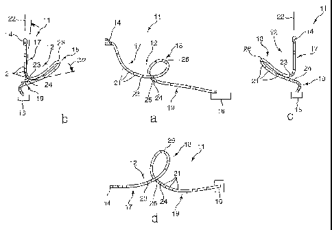
In Figures 4a to d, a further alternative embodiment of
a water chute 11 is represented. Such an embodiment and
its geometry is also referred to as a helical loop.
This embodiment differs, for example, from the
embodiment according to Figure 1 inasmuch as the
starting point 23 and finishing point 24 do not lie
directly adjacent to each other, but are arranged at a
greater distance apart, so that the loop section 18
corresponds to the course of a screw thread. Depending
on the pitch, the starting point 23 and the finishing
point 24 are distanced apart. Such loop sections 18
allow both an upside-down sliding and a roller coaster
ride if the entry speed into the loop section 18 is
insufficiently high. In a loop section of this kind,
the rising and falling sections, as can be seen, for
example, from Figures 4b and c, can be arranged at a
same angle to the vertical 22. Alternatively, one of
CA 02635191 2008-06-17
- 14 -
the two sections can be arranged with a larger or
smaller angle to the vertical 22 or to the summit 26.
All the aforementioned features are respectively per se
fundamental to the invention and can be mutually
combined according to choice.