Note: Descriptions are shown in the official language in which they were submitted.
CA 02635192 2008-06-18
1
Transport installation by aerial rope comprising a vehicle transfer
circuit equipped with a torque motor
Background of the invention
The invention relates to a transport installation comprising a contiriuous
running aerial rope on which vehicles are suspended by means of detachable
grips, said installation having at least one terminal for loading and
unloading
passengers on board the vehicles, said installation comprising:
- detachment means, on entry to the terminal, to uncouple the vehicles and
the rope,
- attachment means, on exit from the terminal, to recouple the vehicles
and the rope,
- a transfer circuit of the vehicles equipped with means for moving the
vehicles comprising at least one set of wheels with pneumatic tires, one
of the wheels of which is coupled with a drive power take-off derived from
the running movement of the rope, said set of wheels being equipped
with drive means whereby each wheel is made to rotate by one of the
adjacent wheels.
State of the art
Conventionally in this type of installation, the transfer circuit connecting
the
up-line and the down-line of the rope comprises a slowing-down section
equipped with a slowing-down device, a speeding-up section equipped with
an accelerating device, the two sections being connected by an intermediate
section wherein the vehicles run at reduced speed equipped with a driving
device of the vehicles. The assembly formed by the accelerating device, the
slowing-down device and the driving device form the means for moving the
vehicle along the transfer circuit.
CA 02635192 2008-06-18
2
Generally, the means for moving the vehicle are formed by one or more sets
of wheels with pneumatic tires staggered along the transfer circuit to
cooperate by friction with a friction track borne by the grips of the
vehicles.
Each of these sets of wheels is equipped with drive means whereby each
wheel of the set is made to rotate by one of the adjacent wheels. These drive
means often comprise transmission belts or idle pinions.
To make the wheels of a set move, one of the wheels of this set can be
connected to a drive power take-off derived from the running movement of
the rope. Such a power take-off is in particular achieved by means of a roller
sheave pressing on the rope and set in motion by the running movement of
the rope.
Another possibility to make the wheels of a set move consists in using a
variable speed motor which drives a transmission belt stretched betweeri two
pulleys one of which is mounted coaxially on one of the wheels, or on one of
the idle pinions when the drive means comprise such pinions.
Depending on the capacity of the installation and the configuration of the
terminals, the number of vehicles taken up by a given set of wheels is
variable. The power required for moving these vehicles is logically
proportional to the number of vehicles. Moreover, the instantaneous power
recovered from the rope by the power take-off of this set is a function of the
adhesion coefficient between the rope and sheave and of the normal force
exerted by the rope on the sheave. The first factor depends on the type of
tire
(modulus of elasticity), on the temperature, on the external conditions
(humidity, frost). The second factor depends on the tension of the rope, the
angle of deviation of the rope on the sheave, and the maximum load
admissible by the sheave.
CA 02635192 2008-06-18
3
For a given set of wheels having a power take-off derived from the rope, the
instantaneous power recovered from the rope by the power take-off and
transmitted to the set of wheels must at all times be equal to the sum of the
power required to move the vehicles present on this set of wheels and of the
power lost in particular due to the efficiencies and reduction ratios of the
mechanics used. If this is not the case, this results in slipping of the
roller
sheave of the power take-off with respect to the rope. The risk of this
slipping
occurring is therefore very high when the capacity of the installation is high
and/or when the external conditions are unfavorable, which is not satisfactory
for the operators. The only solutions to overcome such a risk consist in over-
dimensioning the power take-off and/or in providing an excessive number of
sets of wheels in order to increase the number of power take-offs on the
transfer circuit, resulting in increased manufacturing, installation and
maintenance costs of the transport installations.
The document EP0461954 describes a transport installation in which the
means for moving the vehicles in the disengaged state comprises at least
two consecutive sets of wheels. One of the wheels of one of the sets is
connected to a power take-off derived from the rope, and one of the wheels
of the other set is connected by transmission means to the output shaft of an
electric motor. Along the set equipped with the electric motor, the necessary
power is only delivered by the electric motor. Along the set equipped with the
power take-off, the necessary power is only delivered by the power take-off.
This dissociation has the purpose of defining a speed regulating section
within the means for moving the vehicles to reposition the cars correctly with
a preset spacing. Such a construction does not enable the problems set out
above to be dealt with.
Object of the invention
CA 02635192 2008-06-18
4
The object of the invention consists in providing a transport installation
able
to palliate the risk of slipping of the roller sheave of a power take-off with
respect to the rope in simple manner enabling the manufacturing, installation
and maintenance costs to be reduced.
The installation according to the invention is remarkable in that one of the
wheels of said set of wheels is connected by transmission means to the
output shaft of an electric torque motor generating a constant turning torque
independent of the speed of rotation of said output shaft.
According to the invention, the power transmitted to the means for moving
the vehicles is provided, at all times, on the one hand by the power take-off
derived from running of the rope and on the other hand from the electric
torque motor. The power delivered by the torque motor being equal to
multiplication of the torque supplied, which is of constant value, and of the
speed of rotation of the output shaft, the torque motor therefore transmits a
power of constant value to the means for moving. The rest of the necessary
power is supplied by the power take-off. The power from the power take-off is
therefore variable as in the prior art but reduced by a value equal to the
constant power delivered by the electric torque motor, which enables any risk
of slipping of the roller sheave of said power take-off with respect to the
rope
to be prevented very simply.
According to a preferred embodiment, the wheel coupled to the power take-
off and the wheel connected to the torque motor are distinct and separated
by several wheels.
Other technical features can be used either alone or in combination:
- the transmission means comprise a gearing-down device the input of
which is connected to the output shaft of the torque motor and the output
of which comprises a drive pulley driving a transmission belt engaged in
CA 02635192 2008-06-18
a receiver pulley mounted coaxially on the wheel of the set connected to
said output shaft,
- the means for moving comprise at least two sets of wheels each of which
comprises one wheel connected to a respective torque motor ancl one
5 wheel connected to a respective power take-off.
Brief description of the drawings
Other advantages and features will become more clearly apparent from the
following description of a particular embodiment of the invention given as a
non-restrictive example only and represented in the accompanying drawings,
in which:
- figure 1 schematizes the transfer circuit of a terminal of an example of a
transport installation according to the invention, in top view,
- la figure 2 represents the transfer circuit of figure 1 in transverse cross-
section at the level of the electric torque motor,
- figure 3 illustrates the detail bearing the reference D in figure 2,
- figure 4 is a top view of a part of the transfer circuit.
Description of a preferred embodiment of the invention
An example of a transport installation according to the invention is described
hereafter. An aerial rope 10 of the installation extends in a closed loop
between two passenger loading/unloading terminals, respectively down-hill
and up-hill, passing in the terminals on main pulleys one of which drives the
rope 10 with continuous running. Figure 1 illustrates the down-hill terrninal
which is equipped with a drive pulley 11. Rope 10 supports vehicles 12, for
example chairs, coupled by detachable grips bearing the reference 13 in
figure 2 and staggered along rope 10. The transport installation can comprise
other intermediate terminals provided along the up-line 14 and down-line 15
of rope 10 for loading and/or unloading passengers in vehicles 12.
CA 02635192 2008-06-18
6
At the entry of the terminal, vehicles 12 are detached from down-line 15 of
rope 10 by detachment means, not represented and known as such, and run
on a transfer circuit (represented in figure 2 in cross-section) at reduced
speed in the terminal until they reach up-line 14 of rope 10. A slowing-down
device slows vehicles 12 detached from rope 10 down, whereas on exit an
accelerating device reaccelerates them to a speed equal to that of rope 10 to
enable recoupling to rope 10 without jerks by attachment meansõ not
represented and known as such.
The slowing-down and accelerating devices are both formed by wheels with
pneumatic tires staggered along a section of the transfer circuit,
respectively
slowing-down section A and speeding-up section B, to cooperate by friction
with a friction track 16 (in figure 2) borne by grips 13 of vehicles 12. The
wheels with pneumatic tires of the slowing-down and accelerating devices
are respectively referenced 17A and 17B.
Wheels 17A of slowing-down device are coupled with one another by means
of belts 18A engaged on auxiliary pulleys 19A mounted coaxially to wheels
17A. Each wheel 17A is integral to two auxiliary pulleys 19A, each
cooperating respectively with a belt 18A, one of belts 18A engaging on one of
auxiliary pulleys 19A of one of adjacent wheels 17A and the other of belts
18A cooperating with one of auxiliary pulleys 19A of the other of adjacent
wheels 17A. For driving, at least one of wheels 17A of slowing-down device
is coupled to a first driving power take-off P1 derived from the running
movement of rope 10. Such a power take-off P1 is notably achieved by
means of a roller sheave pressing on rope 10 and set in motion by runnirig of
rope 10. The roller sheave can set a fixedly attached pulley in motion, the
latter transmitting a rotational movement, by means of a transmission belt, to
a pulley fixedly attached to wheel 17A connected to power take-off P1. The
roller sheave can also be directly secured fixedly to wheel 17A connected to
CA 02635192 2008-06-18
7
power take-off P1. For the purpose of driving wheels 17B, the accelerating
device implements a similar solution with at least one wheel 17B coupled to a
second power take-off P2, belts 18B and auxiliary pulleys 19B. Power take-
off P2 of the accelerating device is, in non-restrictive manner, distincl:
from
that of the slowing-down device.
Slowing-down section A and speeding-up section B of the transfer circuit are
joined by an intermediate section C along which vehicles 12 run continuously
at reduced speed by means of a driving device formed by wheelE; with
pneumatic tires. Intermediate section C is subdivided into three successive
parts S1, S2, S3. First part S1 is straight, extends slowing-down section A
downstream, and is equipped with wheels referenced 17C1 belonging 'to the
reduced speed driving device. Last part S3 is straight, extends speeding-up
section B upstream, and is equipped with wheels referenced 17C3 belonging
to the reduced speed driving device. Intermediate part S2 is semi-circular
and joins first and last parts S1 and S3. The wheels of semi-circular part S2
are referenced 17C2 and driven in synchronism with one another, for
example by idle pinions, (not represented) inserted between transmission
pinions 20C2 (figure 1) mounted coaxially with wheels 17C2. Wheels 17C1
and 17C3 of straight parts S1 and S3 are for example mutually driveri in a
similar way to wheels 17A, 17B of slowing-down and accelerating devices,
with respectively auxiliary pulleys 19C1, 19C3 on each wheel 17C1, 17C3
and belts 18C1, 18C3. One of wheels 17C1 of first part S1 is driven in
rotation by one of wheels 17A of slowing-down section A. In like manner, one
of wheels 17C3 of last part S3 is driven in rotation by one of wheels 17B of
speeding-up section B. Driving of wheels 17C2 of intermediate part S2 can
be performed by one of wheels 17C1, 17C3 of at least one of adjacent parts
S1, S3.
CA 02635192 2008-06-18
8
It is clear that the number of parts of intermediate section C can be
different
from three depending on the type of equipment involved. For example, part
Si and/or part S3 can be eliminated.
It is clearly apparent from the above that the transfer circuit of vehicles 12
is
equipped with means for moving the vehicles constituted by the assembly
formed by the slowing-down device, the reduced speed driving device and
the accelerating device. Wheels 17A of the slowing-down device, to which
wheels 17C1 of first part S1 of intermediate section C are added, to vrhich
can be added, when this is the case, wheels 17C2 of intermediate pairt S2
which are driven by one of wheels 17C1 of first part S1, constitute a first
set
of wheels with pneumatic tires. In identical manner, wheels 17B of the
accelerating device, to which wheels 17C3 of last part S3 of intermediate
section C are added, to which can be added, when this is the case, wheels
17C2 of intermediate part S2 which are driven by one of wheels 17C3 of last
part S3, constitute a second set of wheels with pneumatic tires.
Each of the first and second sets of wheels comprises a wheel, respectively
one of wheels 17A and 17B, connected to a respective power take-off P1,
P2. Each of the sets also comprises drive means whereby each wheel of the
set is made to rotate by one of the adjacent wheels of the same set. For the
first set, these drive means are formed, for wheels 17A of the slowing-ciown
device and for those 17C1 of the part of the reduced speed driving device
equipping first part S1, by all the pairs of auxiliary pulleys 19A and 19C1
mounted on these wheels and by associated belts 18A and 18C1. When the
first set also includes at least one of wheels 17C2 of the part of the reduced
speed driving device equipping intermediate part S2, the drive means of the
first set also comprise pinions 20C2 mounted coaxially on these wheels 117C2
and the intercalated idle pinions. In exactly the same way for the second set,
the drive means which the latter comprises are formed, for wheels 17B of the
accelerating device and for those 17C3 of the part of the reduced speed
CA 02635192 2008-06-18
9
driving device equipping last part S3, by all the auxiliary pulleys 19B and
19C3 mounted on these wheels and by associated belts 18B and '18C3.
When the second set also includes at least one of wheels 17C2 of the part of
the reduced speed driving device equipping intermediate part S2, the drive
means of the second set also comprise pinions mounted 20C2 coaxially on
these wheels 17C2 and the intercalated idle pinions.
Figure 2 illustrates first part S1 of intermediate section C of the transfer
circuit
of figure 1, in transverse cross-section near the junction between first part
S1
and intermediate part S2. In conventional manner, the transfer circuit is
equipped with means for guiding the detached vehicles 12. The body of grip
13 bears a first roller sheave 21 to move grip 13 detached from rope 10 on a
first transfer rail 22 performing lateral guiding of grip 13. First transfer
rail 22
presents a U-shaped cross-section open upwards to receive first roller
sheave 21. To prevent grip 13 (and therefore associated vehicle 12) from
rotating, the body of grip 13 comprises a second roller sheave 23 mounted
on the end of an overhanging support arm 24. Second roller sheave 23 is
mounted in a second transfer rail 25 parallel to the first but offset
laterally
towards the inside of the transfer circuit. Second transfer rail 25 presents a
U-shaped cross-section open laterally in the direction of first transfer rail
22.
Such a grip 13 is well known and does not need to be described in greater
detail here.
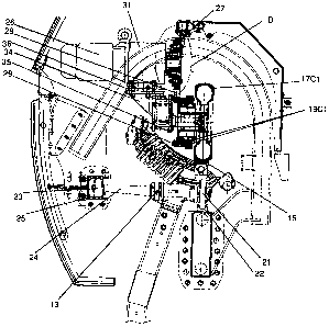
According to the invention and with reference to the figures, one of the
wheels of the first set of wheels defined above is connected to the output
shaft of an electric torque motor 26. For example purposes and as
represented, torque motor 26 is connected to one of the last wheels of the
first set (seen in the running direction of vehicles 12), such as for example
to
one of the last wheels 17C1 of first part S1 of reduced speed intermediate
section C. Torque motor 26 is secured above wheel 17C1 to which its output
shaft is connected, with an offset towards the inside of the transfer circuit,
by
CA 02635192 2008-06-18
means of a motor support 34 at right angles, the side of which facing wheel
17C1 is fixed to a counterplate 35. The side of motor support 34 facing
reducing gear 31 is for its part fixed to an adjustment plate 36 for adjusting
the lateral positioning of torque motor 26.
5
With reference to figure 2, the connection between wheel 17C1 and the
output shaft of torque motor 26 is achieved by transmission means
comprising for example a gearing-down device 31 the input of which is
coupled to the output shaft of torque motor 26 and the output of which
10 comprises a drive pulley 27 driving a transmission belt 28 engaged at its
opposite end in a receiver pulley 29 mounted coaxially on wheel 17C1 of the
first set connected to the output shaft of torque motor 26. Figure 2
iilustrates
that receiver pulley 29 is fixedly secured to the pair of auxiliary pulleys 1
9C1
mounted on wheel 17C1 of the first set connected to the output shaft of
torque motor 26. In figure 2, belts 18C1 are not represented for the sake of
clarity. Detail D of figure 2 is illustrated in figure 3 and represents
assembly of
the drive pulley 27 by clamping by means of bolts 32 against a radial plate 33
fitted on a hub 30 fixedly secured to the output of gearing-down device 31. It
is clear that any equivalent type of transmission means can be used wittiout
departing from the scope of the invention, for example by means of an
assembly with transmission by pinions.
Torque motor 26 in known manner generates a constant turning torque
independent from the speed of rotation of its output shaft. The power
delivered by torque motor 26 is equal to multiplication of the torque supplied
to the output shaft, which is of constant value, and of the speed of rotation
of
the output shaft. For a given running speed of rope 10, torque motor 26
therefore transmits a power of constant value to wheel 17C1 to which it is
connected, and therefore transmits a constant power to the means for
moving the vehicles.
CA 02635192 2008-06-18
11
For the first set of wheels, the power transmitted to the means for moving the
vehicles 12 comes, at all times, on the one hand from power take-off P1
derived from running of rope 10, and on the other hand from electric torque
motor 26. The instantaneous power supplied by power take-off P1 and by
torque motor 26 to the means for moving must, at all times, be equal to the
sum of the power necessary to move vehicles 12 present on this set of
wheels and of the power lost in particular due to the efficiencies and
reduction ratios of the mechanics used. If this is not the case, this results
in
slipping of the roller sheave of power take-off P1 with respect to rope 10.
Depending on the capacity of the installation and the configuration of the
terminals, the number of vehicles 12 taken up by the first set of wheels is
variable. The power necessary to move these vehicles 12 is logically
proportional to the number of vehicles 12. The power transmitted by toirque
motor 26 being constant, this variation of the power necessary to niove
vehicles 12 is compensated by a corresponding variation of the
instantaneous power supplied by power take-off P1 of the first set. The power
coming from power take-off P1 is therefore variable as in the prior artõ but
reduced by a value equal to the constant power delivered by torque motor 26,
which enables any risk of slipping of the roller sheave of power take-of'f P1
with respect to rope 10 to be prevented very simply.
Torque motor 26 further presents the advantage of delivering a constant
torque whatever the running speed of rope 10 without requiring any
additional electronic device, or even a servo-control device. Torque motor 26
thereby performs its function, in downgraded operation of the installation, by
a simple electric power supply. Such a torque motor 26 moreover presents
the advantage of being able to be installed very simply and at low cost on
new or already existing installations.
CA 02635192 2008-06-18
12
The choice of the wheel of the first set that is connected to torque motor 26
presents an importance on operation of the first set. In the exarnple
described, torque motor 26 is connected to the penultimate wheel 17C1 of
first part S1 of reduced speed intermediate section C, which enables wheel
17A connected to power take-off P1 associated with the first set and wheel
17C1 connected to torque motor 26 to be distinct and separated by several
wheels 17A and 17C1. Such a configuration, in the event of absence of
vehicles 12 on the first set of wheels and for the worst climatic conditions,
limits the risk of the power supplied by torque motor 26 exceeding the energy
dissipation capacity by the drive means of the wheels of the set and by
friction of the roller sheave of power take-off P1 on rope 10. Exceeding this
capacity would cause slipping of belts 18A, 18C1 and/or of the roller sheave.
Nevertheless, the choice of the wheel of the first set to which torque motor
26
is connected is not restrictive in the invention. In other words, torque
rriotor
26 can be connected to any wheel 17A, 17C1, or even 17C2, without
departing from the scope of the invention.
Finally, the second set of wheels defined above can also be equipped with a
torque motor (not represented) connected to one of its wheels 17B, 17C3
and even 17C2. In this case, the means for moving vehicles 12 along the
transfer circuit comprise two sets of wheels each of which comprises a wheel
connected to a respective torque motor and a wheel connected to a
respective power take-off P1, P2. In particular, the torque motor associated
with the second set of wheels can be connected to one of the first wheels
17C3 (seen in the running direction of vehicles 12) of last part S3 of reduced
speed intermediate section C. It is clear that the number of sets of wheels
each of which comprises a wheel connected to a respective torque motor and
a wheel connected to a respective power take-off can be more than two
without departing from the scope of the invention.