Note: Descriptions are shown in the official language in which they were submitted.
CA 02635223 2013-09-20
'60557-7945
SANDING TOOL WITH CLAMPING MECHANISM
Background
The present invention relates generally to hand-held, manually-operated
sanding
tools for use with a replaceable sheet of abrasive material such as
'sandpaper. More
particularly, it relates to sanding tools that are easy to load and related
methods of use.
Abrasive sheets, such as conventional sandpaper, are commonly used to hand-
sand
or finish a work surface, such as a wooden surface. With hand-sanding, the
user holds the
sandpaper directly in his/her hand and then moves the sandpaper across the
work surface.
Sanding by hand can, of course, be an arduous task. To facilitate the hand-
sanding
process, the sandpaper can instead be retained by a sanding block or tool
sized to fit within
the user's hand. The sanding block or tool thus makes hand-sanding faster and
easier.
One example of a commercially-available ,sanding block is the 3MTm Rubber
Sanding
Block available from 3M Company of Saint Paul, Minnesota.
U.S. Patent No. 5,168,672 describes another exemplary sanding block or tool in
the
form of an abrasive sheet holder having a base provided with clamping
shoulders formed
in a pair of opposed side edges thereof. A handle is detachably secured over a
rear surface
of the base. The handle has opposed flexible flange walls for clamping opposed
end edge
portions of an abrasive paper sheet that is otherwise positioned over a front
working
surface of the base, with the edge portions of the paper sheet extending over
the clamping
shoulders.
1
CA 02635223 2008-06-25
WO 2007/079034 PCT/US2006/049101
Additionally, U.S. Patent Application Publication No. 2003/0104777 describes a
sanding block or tool including a generally rectangular base housing upon
which a multi-
contoured, generally convex hand-grip is secured. The hand-grip further
defines inwardly
extending concave portions that facilitate easy .and secure grasping by the
user. Further,
an over-center lever clamp mechanism is operative at each end of the sanding
block to
secure the opposed ends of a sandpaper sheet in a releasable manner.
While well-accepted, known sanding blocks may have certain shortcomings. For
example, it is desirable that the sheet of abrasive material be tensioned or
tightly fit about
the sanding block. If the sheet is not tight, it may wrinkle, and the wrinkles
may snag on
the work surface and cause the abrasive sheet to tear. In addition, wrinkles
may cause the
work surface to be damaged or sanded unevenly. These concerns arise with
flexible flat
sheets of abrasive material, such as conventional sandpaper, as well as with
resilient
flexible abrasive sheets that are thicker than conventional sandpaper, such as
the sheet-like
abrasive materials described in, for example, Minick et al., U.S. Patent No.
6,613,113.
Unfortunately, the mechanisms by which conventional sanding blocks or tools
effectuate
loading of the abrasive sheet do not consistently achieve the desired,
tensioned fit.
In particular, the common technique by which known sanding blocks are loaded
with an abrasive sheet generally entails securing opposing ends of the
abrasive sheet to
opposite sides of the sanding block. With one approach, a user attempts to
simultaneously
secure the opposing ends of the abrasive sheet to the sanding block while at
the same time
tensioning the abrasive sheet. This requires considerable dexterity, and often
times the
user is unable to achieve satisfactory results. Alternatively, the user can
sequentially
mount a first end portion of the abrasive sheet to one side of the sanding
block, wrap the
abrasive sheet about a bottom of the sanding block, and then secure the second
end portion
of the sheet to the opposite side of sanding block. A tension is theoretically
created and
maintained while wrapping the sheet about the bottom. While this technique is
physically
easier to perform, it can be equally frustrating for the user. Namely, it is
difficult at best to
properly estimate the amount (i.e., length) of the first end portion of the
abrasive sheet to
initially secure to the first side of the sanding block such that when the
abrasive sheet is
wrapped about the bottom, a proper length remains for securement to the
opposing side of
the sanding block. For example, if an excessive length of the abrasive sheet
is initially
2
CA 02635223 2013-09-20
60557-7945
secured to the sanding block, there may not be a sufficient length remaining
to wrap about
the sanding block and secure to the opposing side thereof. Conversely, if too
short a
length of the abrasive sheet is initially secured to the sanding block, it may
be problematic
to secure the second end to the opposing side of the sanding block as the
excessive,
remaining length that interferes with proper functioning of the securement
mechanism;
similarly, it may be impossible to achieve desired tensioning of the abrasive
sheet, again
due to the excessive remaining length. In either case, the user is required to
release the
first end from the sanding block and try again. Clearly, this can be
frustrating for the user.
In light of the above, a need exists for a sanding tool that is easy to
consistently
and satisfactorily load with a sheet of abrasive material in a manner that
tightly secures the
abrasive sheet.
=
Summary
Aspects of the present invention relate to a hand-held, manually-operated
sanding
tool for use with a replaceable sheet of abrasive material. The sanding tool
includes a base
member and a clamping mechanism. The base member defines first and second
ends, a
bottom surface extending between the first and second ends, a contact surface
formed
opposite the bottom surface and extending from the first end, and at least one
tooth
extending from the contact surface. The clamping mechanism is pivotally
connected to
the base member at a pivot point. The clamping mechanism defines a front
section
opposite the pivot point and is movable about the pivot point between an open
position
and a closed position. In the open position, the front section is spaced from
the contact
surface to establish a gap between the clamping mechanism and the contact
surface for
receiving an end portion of a sheet of abrasive material. In the closed
position, the
clamping mechanism is more proximate the contact surface and the front section
is more
proximate the at least one tooth than when the clamping mechanism is in the
open
position,
3
CA 02635223 2013-09-20
0557-7945
There is also provided a method of sanding with a hand-held, manually
operated sanding tool, the method comprising: providing a sanding tool
including: a base
member defining first and second ends, a bottom surface extending between the
first and
second ends, a contact surface formed opposite the bottom surface and
extending from the
first end, and at least one tooth extending from the contact surface, and a
clamping mechanism
pivotally connected to the base member at a pivot point, the clamping
mechanism defining a
front section opposite the pivot point; positioning the clamping mechanism in
an open
position, in which the front section is spaced from the first contact surface
to establish a gap
between the clamping mechanism and the contact surface; placing a replaceable
sheet-like
abrasive material within the gap; moving the clamping mechanism about the
pivot point from
the open position to a closed position to clamp a first portion of the sheet-
like abrasive
material between the clamping mechanism and the contact surface; and locking
the clamping
mechanism in the closed position to maintain the sheet-like abrasive material
between the
clamping mechanism and the contact surface.
Brief Description of the Drawings
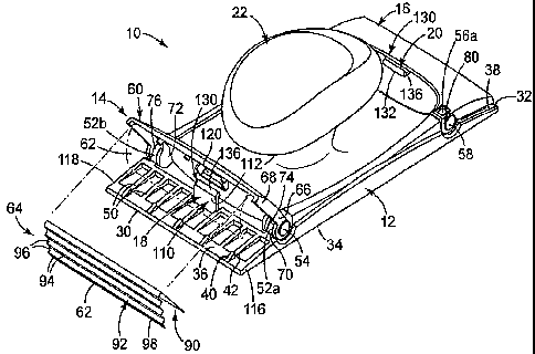
FIG. 1 is a perspective, partially-exploded view of a hand-held, manually-
operated sanding tool according to principles of the present invention;
FIG. 2 is a perspective view of a portion of the sanding tool of FIG. 1;
FIG. 3 is a side view of a portion of the sanding tool of FIG. 1, illustrating
initial loading of a sheet-like abrasive material;
FIG. 4 is a side view of a portion of FIG. 3 with the clamping mechanism in a
closed position;
FIG. 5 is a cross-sectional view of FIG. 4 taken along the line 5-5;
FIG. 6 is a side view of the tool of FIG. 1 loaded with a sheet-like abrasive
material;
4
CA 02635223 2013-09-20
. *60557-7945
FIG. 7 is a perspective view of another embodiment hand-held, manually
operated sanding tool according to principles of the present invent ion; and
FIG. 8 is another perspective view of a portion of the sanding tool of FIG. 7
with the clamping mechanism in an open position.
Detailed Description
One embodiment of a hand-held, manually-operated sanding tool or sanding
block 10 is shown in FIG. 1. The term "manually-operated" refers to the fact
that the tool 10
is not a power tool. That is, all of the power for the tool 10 is provided by
a user (not shown),
and the tool 10 itself does not include a motor. It will be recognized,
however, that principles
of the present invention may be applied to a power tool and are not
necessarily limited to
manually-operated sanding tools.
The sanding tool 10 is described below as being useful with sheet-like
abrasive
material. As used throughout this specification, the terms "sheet-like
abrasive material" and
"sheet of abrasive material" are used interchangeably and refer to thin,
flexible, generally
square or rectangular sheets of abrasive material having discrete ends (or
edges) that can be
attached to a sanding block. Such sheet-like abrasive materials include, for
example,
conventional sandpaper, flexible sanding scrims, non-woven abrasive materials
such as
ScotchBriteTM available from 3M Company, St. Paul, Minnesota, and thin
flexible abrasive
sheet materials such as those described in U.S. Patent No. 6,613,113 (Minick
et al.). The tool
10 may also find use with non-abrasive sheet-like materials such as dust
removing tack cloths.
However, the terms "sheet-like abrasive material" and "sheet of abrasive
material" do not
4a
CA 02635223 2008-06-25
WO 2007/079034 PCT/US2006/049101
include so-called endless belts of abrasive material commonly used with power
sanding
tools, die cut sheets for power detail sanding tools, or abrasive sheets
having their own
attachment means, such as adhesive or hook-and-loop fasteners, that
independently
facilitate attachment to a tool. =
With the above in mind, in one embodiment, .the sanding tool 10 includes a
base
member 12, first and second clamping mechanisms 14, 16, and first and second
alignment
devices 18, 20. In some embodiments, the sanding tool 10 further optionally
includes a
handle 22. As made clear below, the base member 12, the clamping mechanism(s)
14
and/or 16, and the alignment device(s) 18 and/or 20 can assume a wide variety
of forms
apart from that shown in FIG. 1 in accordance with the principles of the
present invention.
Regardless, and in general terms, the first and second clamping mechanisms 14,
16 are
pivotally associated with opposing ends, respectively, of the base member 12.
The first
alignment device 18 extends at least partially between the base member 12 and
the first
clamping mechanism 14, whereas the second alignment device 20 extends at least
partially
between the base member 12 and the second clamping mechanism 16. During use,
and as
described in greater detail below, the first and second alignment devices 18,
20 promote
consistent loading of a sheet of abrasive material (not shown) with the
clamping
mechanisms 14, 16 in a simplified manner.
In one embodiment, the base member 12 defines first and second opposed ends
30,
32, and a generally planar bottom surface 34 against which a sheet of abrasive
material
(not shown) extends. While the base member 12 is illustrated in FIG. 1 as
having a
generally rectangular shape, a variety of other shapes can be provided that
lend themselves
for use with conventional sheet-like abrasive materials. For example, the base
member 12
can be configured such that one or both of the first and second ends 30, 32
define a
triangular or curved shape. Further, the first and second ends 30, 32 need not
be identical
in shape.
In one embodiment, regardless of an overall shape, the base member 12 forms a
first upper contact surface 36 opposite the bottom surface 34 and extending
from the first
end 30. Though substantially hidden in FIG. 1, a second upper contact surface
38
(referenced generally) is similarly formed opposite the bottom surface 34,
extending from
the second end 32. In one embodiment, the upper contact surfaces 36, 38 are
angled or
CA 02635223 2008-06-25
WO 2007/079034 PCT/US2006/049101
inclined. In this manner, the upper contact surfaces 36, 38 and the bottom
surface 34 form
an acute angle relative to the associated end 30, 32, respectively. In the
illustrated
embodiment, the contact surfaces 36, 38 are defined by the exposed upper
surfaces of a
plurality of spaced ribs 50 (shown for the first contact surface 36 in FIG.
1). With this one
configuration, the contact surface area between the sheet-like abrasive
material (not
shown) and the associated contact surface 36 or 38 is decreased (as compared
to a
continuous surface), thereby allowing the sheet to slide upwardly along the
respective
contact surfaces 36, 38 more readily to tension the sheet-like abrasive
material as
described below. Alternatively, the first and/or second contact surfaces 36
and/or 38 can
be defined in a variety of other manners, need not be identical and need not
necessarily be
angled or inclined relative to the bottom surface 34.
In one embodiment, one or more teeth 40 extend from each of the contact
surfaces
36, 38 upwardly (relative to the orientation of FIG. 1). The teeth 40
extending from the
contact surfaces 36, 38 are linearly aligned and laterally spaced (relative to
a length of the
base member 12) along the respective contact surface 36 or 38. In one
embodiment, each
of the teeth 40 is positioned at or near the respective end 30 or 32 to
prevent or decrease
the likelihood that each tooth 40 will substantially interfere with movement
of the sheet-
like abrasive material (not shown) movement upwardly along the respective
contact
surface 36, 38 during loading as described above and as will be further
described below.
In one configuration, each tooth 40 may laterally be positioned to align with
one of the
plurality of spaced ribs 50. Alternatively, a single tooth 40 extends along an
entire width
of or a smaller portion of the width of the. first end 30 of base member 12.
In one
embodiment, each tooth 40 is formed as a ramp extending increasingly upwardly
(i.e.,
increased height) from the contact surface 36, 38 as the tooth 40 extends away
from the
respective end 30 or 32. Accordingly, each tooth 40 defines a point 42
opposite the
respective contact surface 36 or 38.
As described below, the base member 12 is configured to facilitate pivoting or
rotatiOnal attachment thereto by the first and second clamping mechanisms 14,
16. For
example, in one embodiment, the base member 12 forms a pair of posts 52a, 52b
adjacent
the first contact surface 36 opposite the first end 30. The posts 52a, 52b are
laterally
aligned (relative to a length of the base member 12) and are configured to
receive a
6
CA 02635223 2008-06-25
WO 2007/079034 PCT/US2006/049101
corresponding component associated with the first clamping mechanism 14 in a
manner
allowing for rotation of the first clamping mechanism 14 relative to the posts
52a, 52b. A
wide variety of other structure(s) and/or mechanisms can be provided for
rotatably
connecting the first clamping mechanism 14 to the base member 12. Regardless,
a pivot
point 54 (referenced generally) is established by the base member 12 about
which the first
clamping mechanism 14 rotates or pivots. In one embodiment in which the first
and
second clamping mechanisms 14, 16 are similarly constructed, the base member
12 forms
a second set of posts 56a, 56b (it being understood that the post 56a is
partially illustrated
in FIG. 1 and the post 56b is hidden) for rotatably receiving corresponding
features of the
second clamping mechanism 16. Once again, a pivot point 58 is established, and
a wide
variety of other configurations can be used in place of the posts 56a, 56b.
Even further, in
alternative embodiments, the second clamping mechanism 16 is not substantially
similar
to the first clamping mechanism 14 and/or is replaced with a conventional
mechanism for
securing the sheet-like abrasive material to the second end 32 of the base
member 12, such
that the posts 56 can be eliminated.
In one embodiment, the first and second clamping mechanism 14, 16 are
identical.
Thus, the following description of the first clamping mechanism 14 applies
equally to the
second clamping mechanism 16 and vice versa, it being understood that with
other
embodiments, the second clamping mechanism 16 has a different construction
than the
first clamping mechanism 16 and/or can be replaced, for example, with a
conventional
sheet securement mechanism. With this in mind, the clamping mechanism 14
includes a
pivoting member 60 and a gripping surface 62 (shown with phantom lines of FIG.
1)
provided by, as illustrated in the embodiment of FIG. 1, a tensioning member
64 (it being
understood that the tensioning member 64 is illustrated apart from the
pivoting member 60
in FIG. 1 for clarity). The pivoting member 60 and the tensioning member 64
can assume
a wide variety of forms varying from that shown in FIG. 1. In general terms,
however, the
pivoting member 60 forms a mounting section 66 (referenced generally) and a
front
section 68 (referenced generally). The mounting section 66 is configured for
pivotable or
rotatable connection to the base member 12. Upon final assembly, the gripping
surface 62
extends from the front section 68.
7
CA 02635223 2008-06-25
WO 2007/079034 PCT/US2006/049101
In one embodiment, the pivoting member 60 is an integral or unitary body, with
the mounting section 66 including first and second pairs 70, 72 of legs, each
defining a
slot 74, 76 (referenced generally). The slots 74, 76 are sized to receive a
corresponding
one of the posts 52a, 52b provided with the base member 12 such that the
corresponding
pair of legs 70, 72 are rotatably secured to the posts 52a, 52b, respectively,
upon final
assembly. Alternatively, and as mentioned above, the pivoting member 60 can be
configured to include -a variety of other structure(s) and/or mechanisms
adapted to
facilitate rotatable or pivotable connection of the pivoting member 60 to the
base member
12.
As illustrated in FIG. 2, in one example, the slot 74 is further defined by a
transverse surface 80 extending between the pair of legs 70 nearest the first
end 30 (it
being understood that a similar transverse surface (unnumbered) is provided
with the slot
76). In one embodiment, the pair of legs 70 extends from the transverse
surface 80 to
form the slot 74 with no other transverse members extending between the pair
of legs 70.
As such, the slot 74 is formed to be substantially U-shape to rotatably
receive the post 52a
upon assembly. The lack of transverse members between the legs 70 other than
the
surface 80 permits the pivoting member 60 to opened in a wide manner (i.e., to
be pivoted
further away from the contact surface 36). More specifically, as illustrated
in FIG. 3, the
pivoting member 60 opens to define an angle 0 between the pivoting the first
contact
surface 36 and the pivoting member 60. In one embodiment, the angle 0 is
greater than or
equal to 60 , more preferably, is greater than or equal to 800
.
Once again referring to FIG. 1, in one embodiment, the tensioning member 64 is
a
thin flexible strip of metal, for example, forming a leaf spring-like
configuration, that
generally returns to the orientation shown in FIG. 1. Alternatively, the
tensioning member
64 can be formed of other materials, such as plastic(s), film(s), etc. In one
embodiment,
= the tensioning member 64 includes a support wall 90 and a gripping wall
92. The support
wall 90 is configured for attachment to the pivoting member 60. The gripping
wall 92
extends from the support wall 90 and defines the gripping surface 62. Upon
final
assembly, the gripping wall 92, and thus the gripping surface 62, extends
generally
inwardly (i.e., toward the contact surface 36) from the front section 68 of
the pivoting
member 60.
= 8
CA 02635223 2008-06-25
WO 2007/079034 PCT/US2006/049101
In one embodiment, as illustrated in FIG. 1, the gripping wall 92 and the
gripping
surface 62 are each formed with a stair-like or stepped configuration. More
specifically,
gripping wall 92 includes a plurality of bends 94 in alternating directions,
which extend
laterally across an entire width of the gripping wall 92 to define a plurality
of steps 96.
Alternatively, at least some of the bends 94, and in particular, one or more
of the bends 94,
can extend across less than an entire width of the gripping wall 92 andior can
be
intermittent. In addition, while the bends 94 are illustrated as being
approximately
equidistantly spaced relative to a length of the gripping wall 92, other, more
random or
other suitable spacings are equally acceptable. In one embodiment, a width of
the
gripping wall 92 tapers adjacent a free edge 98 of the gripping wall 92
opposite the
support wall 90. Alternatively, a width of the gripping wall 92 can be uniform
or
otherwise vary from that shown in FIG. 1. Regardless, in one embodiment, at
least the
first bend 94 is substantially parallel with the free edge 98. Alternatively,
the gripping
surface 62 can be provided with a variety of other configurations, such as
with a smooth,
pitted, or other suitable gripping surface 62. For example, the tensioning
member 64, and
in particular the gripping wall 92, can assume a variety of other forms
varying from that
shown in FIG. 1. Even further, the gripping surface 62 can be provided as an
integral,
unitary portion of the pivoting member 60.
Upon final assembly, and with additional reference FIGS. 2-4, the first
clamping
mechanism 14 is rotatably connected to the base member 12. This construction
allows the
first clamping mechanism 14 to pivot (at the pivot point 54) between an open
position as
shown in FIG. 3 and a closed position as shown in FIG. 4 (also shown for the
second
clamping mechanism 16 in FIG. 1). In the open position, the front section 68
of the
pivoting member 60 is spaced from the first contact surface 36, establishing a
gap 100
(referenced generally) between the first clamping mechanism 14 (and in
particular, the
gripping surface 62) and the first contact surface 36. In the open position,
then, a sheet-
like abrasive material 102, and in particular a first end portion 104 thereof,
can be inserted
within the gap 100 for subsequent securement to the first contact surface 36
via the first
clamping mechanism 14.
Of note, since the pivoting member 60 forms the slot 74 with no members
extending between the pair of legs 70 other than the transverse surface 80
(FIG. 2), no
9
CA 02635223 2008-06-25
WO 2007/079034 PCT/US2006/049101
such members are present to further limit the amount that pivoting member 60
can be
pivoted away from the first contact surface 36 (i.e., the amount that the
pivoting member
60 can be opened). Accordingly, the clamping mechanism 14 can be opened to
define a
relatively wide angle 0, which provides additional clearance for a user's
fingers (not
shown) during loading and unloading of the sheet material from the sanding
tool 10. In
this way, the wide angle 0 increases the ease of loading as well as the
general usability of
the sanding tool 10.
During use of the sanding tool 10, the first alignment device 18 provides a
positive
stop surface 112 (described in greater detail below) for facilitating proper
placement of the
sheet-like abrasive material 102 (FIG. 2) relative to the first end 30 of the
base member
12. With continued reference to FIGS. 1 and 3, in one embodiment, the first
and second
alignment devices 18, 20 are similarly configured such that the following
description of
the first alignment device 18 equally applies to the second alignment device
20.
Alternatively, and as described in greater detail below, the first and second
alignment
devices 18, 20 can assume different forms; even further, the second alignment
device 20
can be eliminated.
In one embodiment, the first alignment device 18 includes a tab 110 extending
at
least partially between the first contact surface 36 and the first clamping
mechanism 14.
In particular, with the one embodiment of FIGS. 1 and 3, the tab 110 projects
upwardly
(relative to an orientation of FIGS. 1 and 3) from the first contact surface
36 toward the
first clamping mechanism 14. The tab 110 and the base member 12 can be
integrally
formed as a unitary body; alternatively, the tab 110 can be separately formed
and
assembled to the base member 12. Regardless, the tab 110 is longitudinally
positioned
(relative to a length of the base member 12) between the first end 30 and the
pivot point
54. More particularly, the tab 110 defines the stop surface 112 otherwise
spaced from the
first end 30. The stop surface 112 is positioned forward of the pivot point 54
such that the
sheet-like abrasive material 102, otherwise traversing along the first contact
surface 36,
will interface with the stop surface 112, and thus will not extend to the
pivot point 54.
Thus, the tab 110, and in particular the stop surface 112, effectively defines
a trailing side
114 (referenced generally in FIG. 3) of the gap 100 (i.e., longitudinally
opposite an
entrance side of the gap 100 generally defined at the first end 30).
CA 02635223 2008-06-25
WO 2007/079034 PCT/US2006/049101
In one embodiment, a longitudinal distance between the stop surface 112 and
the
first end 30 correlates with a length of the base member 12 (i.e., distance
between the first
and second ends 30, 32), as well as, in some embodiments, with an expected,
standardized
length of the sheet-like abrasive material 102 intended to be used with the
sanding tool 10.
In particular, and as described in greater detail below, a longitudinal length
between the
stop surface 112 and the first end 30 is such that when the sheet-like
abrasive material 102
is disposed against the stop surface 112, a sufficient length remains for
wrapping about the
first end 30, along the bottom surface 34, and into engagement with the second
contact
surface 38.
As best shown. in FIG. 1, the tab 110 is, in one embodiment, laterally offset
from
opposing sides 116, 118 of the first contact surface 36. For example, the tab
110 can be
laterally centered relative to the opposing sides 116, 118 (i.e., relative to
a width of the
first contact surface 36). This one preferred location increases a likelihood
that during an
abrasive sheet loading operation, the stop surface 112 will be contacted by
the sheet-like
abrasive material 102 (FIG. 2). Alternatively, other locations are also
acceptable as
described below.
In one embodiment, the first clamping mechanism 14 is configured to
accommodate the tab 110 in the closed position (shown in FIG. 2). For example,
the
pivoting member 60 forms an aperture 120 sized and positioned such that upon
final
assembly, the aperture 120 is aligned with the tab 110 and permits passage of
the tab 110
through the aperture 120 as the pivoting member 60 transitions from the open
position to
the closed position. Alternatively, projection of the tab 110 from the first
contact surface
36 can be reduced from that shown in FIGS. 1-3, such that the aperture 120
need not be
included. Preferably, however, the tab 110 is of a fairly significant height
so as to ensure
interface with the sheet-like abrasive material 102 (FIG. 2) otherwise being
loaded to the
first contact surface 36.
The tab 110 further forms, in one embodiment, a portion of a locking mechanism
130 (referenced generally in FIG. 1) that selectively locks or secures the
first clamping
mechanism 14 in the closed position (i.e., shown for the second clamping
mechanism 16).
In particular, the locking mechanism 130 includes; in one embodiment, the tab
110, the
aperture 120, and an engagement surface 132. To this end, and with reference
to FIG. 3
11
CA 02635223 2008-06-25
WO 2007/079034 PCT/US2006/049101
the tab 110 is formed to include a finger 134, which otherwise forms the stop
surface 112
and a latch body 136. The latch body 136 extends from the finger 134 opposite
the
contact surface 36, preferably in a direction away from the first end 30.
The engagement surface 132 is defined at a perimeter of the aperture 120.
Referring to FIG. 2, in one embodiment, the engagement surface 132 is formed
with a
ramp member 140 extending from a contoured surface 142 of the pivoting member
60,
which has a substantially curvilinear or other suitable contour. In this
manner, the ramp
member 140 is configured to form the engagement surface 132 as a substantially
planar
surface for receiving the latch body 136 regardless of the contour of the
pivoting member
60. With this configuration, in the closed position, the finger 134 extends
through the
aperture 120, with the latch body 136 abutting against the substantially
planar engagement
surface 132, such that the tab 110 secures the first clamping mechanism 14
relative to the
base member 12. In one example, the substantially planar formation of the
engagement
surface 132 permits the latch body 136 to contact the engagement surface over
a larger
contact area than would otherwise be realized, thereby, more reliably securing
the
clamping mechanism 14 relative to the base member 12. In one embodiment, the
substantially planar engagement surface 132 further permits the contoured
surface 142 to
be formed in a shallower manner.
In one embodiment, to facilitate passage of the latch body 136 through the
aperture
120 as the pivoting member 60 transitions from the open position to the closed
position, as
well as to permit selective disengagement of the latch body 136 from the
engagement
surface 132, the tab 110 can be slightly deflectable from the upright
orientation illustrated
in FIG. 1. With this construction, then, the latch body 136 can be forced
slightly toward
the first end 30, via deflection of the finger 134, to permit passage through
the aperture
120. Alternatively, the locking mechanism 130 can assume a variety of other
forms, and
need not be identical relative to the first and second clamping mechanisms 14,
16. In
some embodiments, a locking mechanism is not provided for one or both of the
clamping
mechanisms 14 and/or 16.
While the first alignment device 18 has been described as including the tab
110,
other configurations can be employed, several examples of which are provided
below. For
example, the stop surface. 112 can be defined by one or more other structures
that may or
12 =
CA 02635223 2008-06-25
WO 2007/079034 PCT/US2006/049101
may not be tabs (e.g., a continuous or discontinuous bump or flange).
Regardless, the first
alignment device 18 is configured to provide the stop surface 112 as defining
the trailing
side 114 of the gap 100 for assisting in proper positioning of the sheet-like
abrasive
material 102 relative to the first end 30 as part of a loading operation
described below.
With specific reference to FIG. 3, loading of the sheet-like abrasive material
102 to
the tool 10 begins with transition ing of the first clamping mechanism 14 to
an open
position such that the gap 100 is formed. The first end portion 104 of the
sheet-like
abrasive material 102 (otherwise terminating at an edge 150) is manually
inserted by a
user (not shown) into the gap 100. In particular, with the first clamping
mechanism 14 in
the open position, the first end portion 104 is inserted into the gap 100 at
or about the first
end 30 and positioned along the first contact surface 36. In this regard, the
first end
portion 104 is maneuvered or directed within the gap 100 (i.e., away from the
first end 30)
until the edge 150 contacts or abuts against the stop surface 112 provided by
the tab 110.
Further movement of the edge 150 beyond the stop surface 112 (i.e., closer to
the pivot
point 54) is thus impeded, ensuring that a desired length of the sheet-like
abrasive material
102 is within the gap 100 and that the edge 150 will not interfere with
subsequent
movement of the clamping mechanism 14 at the pivot point 54.
With the first end portion 104 properly located within the gap 100, the first
clamping mechanism 14 is then transitioned (e.g., rotated) to a closed
position as shown in
FIG. 4. As the clamping mechanism 14 is urged toward the contact surface 36,
the
tensioning member 64 further grips the first end portion 104 of the abrasive
material 102
and deflects to move the first end portion 104 upwardly along the inclined
contact surface
36 and thus away from the associated end 30. This action draws the sheet of
abrasive
material 102 further into the gap 100.
In the closed position, the gripping surface 62 engages the sheet-like
abrasive
material 102, frictionally capturing the first end portion 104 between the
gripping surface
62 and the first contact surface 36. Thereby, the first end portion 104 is
secured to the
sanding tool 10, with a remainder 152 (reference generally) of the sheet-like
abrasive
material 102 freely extending from the first end 30 of the base member 12.
When the
sheet-like abrasive material 102 is held between the gripping surface 62 and
the first
contact surface 36, the sheet-like abrasive material 102 also interfaces with
the point(s) 42
13
CA 02635223 2008-06-25
WO 2007/079034 PCT/US2006/049101
of the one or more teeth 40 (FIG. 3) extending upwardly from the first contact
surface 36.
In one embodiment, the sheet-like abrasive material 102 is further pinched
between the
teeth 40 and the gripping surface 62 to more robustly secure the sheet-like
abrasive
material 102 in place in the sanding tool 10.
Continuing to refer to FIG. 4, in one embodiment, upon closure of the first
clamping mechanism 14, the at least one tooth 40 is configured to align or
correspond with
an indention 153 defined by the gripping surface 62. As such, the sheet-like
abrasive
material 102 is pinched between each tooth 40 and the gripping surface 62 to
position the
sheet-like abrasive material 102 in a compound bend or curve, which is
generally
referenced at 160. The compound bend 160 of the sheet-like abrasive material
102 is
formed when the sheet-like abrasive material 102 bends in a first direction
followed by a
bend in a second direction that is different from the first direction. The
compound bend
160 is longitudinally oriented relative to a length of the base member 12. The
compound
bend 160 creates a tortuous path for the release of the sheet-like abrasive
material 102
form the sanding tool 10, thereby preventing or at least substantially
decreasing the
likelihood that the sheet-like abrasive material 102 will unintentionally be
dislodged from
between the gripping surface 62 and the first contact surface 36 during use or
due to other
commonly applied tensile forces. As such, to remove the sheet-like abrasive
material 102
from the sanding tool 10, the first clamping mechanism 14 would generally be
unlocked*
and pivoted away from the first contact surface 36 to release the sheet-like
abrasive
material 102.
Referring to the cross-sectional view of FIG. 5, in one embodiment, a
plurality of
teeth 40 are spaced along the first end 30 of the sanding tool 10 and are
sufficiently
laterally spaced from one another to create a laterally orientated compound
bend or curve
generally indicated at 162 as the sheet-like abrasive material 102 is forced
to bend around
each tooth 40. More specifically, the teeth 40 are spaced to prevent
"bridging" of the
sheet-like abrasive material 102 between the teeth 40, wherein the sheet-like
abrasive
material 102 would extend straight across the teeth points 42 without curving
down
(relative to the orientation of FIG. 5) to define valleys 164 therebetween.
The compound
curvature 162 of the sheet-like abrasive material 102 laterally between and
over the teeth
40 further bolsters securement of the sheet-like abrasive material 102 by the
sanding tool
=
14
CA 02635223 2008-06-25
WO 2007/079034 PCT/US2006/049101
10, which, consequently, also serves to prevent or at least substantially
decrease the
likelihood that the sheet-like abrasive material 102 will unintentionally be
dislodged from
between the gripping surface 62 and the first contact surface 36 during use or
other
commonly applied tensile force.
In one embodiment, the teeth 40 may partially or fully penetrate or otherwise
hook
into the sheet-like abrasive material 102 to more effectively lock the sheet-
like abrasive
material 102 in place relative to the first contact surface 36. Accordingly,
the teeth 40
facilitate securement of the sheet-like abrasive material 102 between the
first contact
surface 36 and the gripping surface 62 even when a force of tension is applied
to the sheet-
like abrasive material 102 that could otherwise pull the sheet-like abrasive
material 102
out of gap 100 and away from the first end 30. In particular, the teeth 40
facilitate
securement of any form of the sheet-like abrasive material 102, such as
conventional
sandpaper, flexible sanding scrims, non-woven abrasive materials such as
ScotchBriteTM
available from 3M Company, St. Paul, Minnesota, and thin flexible abrasive
sheet
materials such as those described in U.S. Patent No. 6,613,113, which was
mentioned
above.
With reference to FIG. 6, once the first end portion 104 of the sheet-like
abrasive
material 102 is secured relative to the first contact surface 36, the
remainder 152 of the
sheet-like abrasive material 102 is wrapped about the first end 30, along the
bottom
surface 34, and directed toward the second end 32. A second end portion 154 of
the sheet-
like abrasive material 102 is then secured to the second contact surface 38,
for example via
the second clamping mechanism 16 in a manner similar to that previously
described with
respect to operation of the first clamping mechanism 14. While an edge 156
defined by
the second end portion 154 is shown in FIG. 6 as approximately contacting the
second
alignment device 20, this relationship is not required. That is to say,
securement of the
second end portion 154 to the tool 10 can be accomplished independent of an
exact length
of material actually extending along the second contact surface 38.
Regardless, a user is
able to tension the sheet-like abrasive material 102 about the bottom surface
34 (i.e.,
because the first end portion 104 is secured to the tool 10, the user can
"pull" on the
remainder 152 while wrapping), resulting in a tight, tensioned fit.
CA 02635223 2008-06-25
WO 2007/079034 PCT/US2006/049101
Although described as forcing the sheet-like abrasive material to form one or
more
of a lateral or longitudinally oriented compound bend, in one embodiment, in
which a thin
flexible abrasive sheet materials such as those described in U.S. Patent No.
6,613,113
(Minick et al.) are used, the teeth 40 may alternatively or additionally fit
within voids of
the abrasive sheet material, thereby, grasping the sheet-like abrasive
material to once again
prevent unintentional dislodgement of the sheet-like.abrasive material during
use.
In view of the above, the first alignment device 18 allows a user to employ
the
above-described sequential loading technique, confident that following
securement of the
first end portion 104, the remainder 152 (FIG. 4) is of sufficient length to
"reach" the
second end 32. This is especially applicable to instances in which*the sheet-
like abrasive
material 102 used with the sanding tool 10 is an off-the-shelf product having
a
standardized length. For example, but in no way limiting, sheet-like abrasive
materials are
commonly sold having a length of 9 inches (either full size sheets (e.g., 9
inch x 11 inch)
that a user (not shown) can tear to a desired width, or partial size sheets
having a
decreased width). Regardless, with this standardized length in mind, a
longitudinal
location of the stop surface 112 relative to the first end 30 is selected to
ensure that a
sufficient length of the sheet-like abrasive material 102 (i.e., the remainder
152 described
with reference to FIG. 4) is available for wrapping about the bottom surface
34 and
engagement with the second contact surface 38 (e.g., via the second clamping
mechanism
16). That is to say, appropriate loading of a standardized length of sheet-
like abrasive
material 102 can be consistently achieved by initially locating the edge 150
against the
stop surface 112; the user is then assured that enough length remains for
attachment to the
second contact surface 38.
In one embodiment, in the closed position, the locking mechanism 130
(referenced
generally in FIG. 6) operates to secure the first clamping mechanism 14
relative to the
base member 12, thus preventing unintentional dislodgement of the first end
portion 104
= from the sanding tool 10. In one embodiment, the planar configuration of
the engagement
surface 132 allows the first clamping mechanism 14 to be more effectively
locked in the
closed position. In one embodiment, the second clamping mechanism 16 is also
locked in
a closed position via a separate locking mechanism.
16
CA 02635223 2008-06-25
WO 2007/079034 PCT/US2006/049101
While the sanding tool 10 has been described as forming the first and second
alignment devices 18, 20 to each include a single tab (i.e., the tab 110) that
is otherwise
laterally centered relative to a width of the corresponding contact surface,
in alternative
embodiments, two or more tabs can be employed. Although tab 110 is described
above as
projecting from the first contact surface 36, in one embodiment, one or more
tabs can
alternatively or additionally be included that project from the corresponding
clamping
mechanism 14 or 16. For example, the tab 110 of FIG. 1 can project from the
first
clamping mechanism 14 (e.g., integrally formed with the pivoting member 60 as
a unitary
body).
Another embodiment of a sanding tool 200 in accordance with principles of the
present invention is shown in FIG. 7. The sanding tool 200 includes a base
member 202,
first and second clamping mechanisms 204, 206, and a first alignment device
208
(referericed generally). The base member 202 defines first and. second ends
220, 222, a
bottom surface 224 (referenced generally), and first and second upper contact
surfaces
226, 228 (referenced generally). In one embodiment, the clamping mechanisms
204 and
206 are similar to the clamping mechanisms 14 and 16 (FIG. 1) described above
and
respectively interact with the base member 202 in a manner similar to the
interaction
between the clamping mechanisms 14 and 16 and the base member 12 (FIG. 1) as
described above except where explicitly differentiated herein. The bottom
surface 224 is
generally planar. A sheet-like abrasive material (not shown) is configured to
extend from
around the first end 220 across the bottom surface 224 and around the second
end 222.
Unlike previous embodiments, the first end 220 defines a triangular-like
shape,
with the first clamping mechanism 204, and in particular, a pivoting member
230 thereof,
defining a similar shape. The alignment device 208 is similar to the alignment
device 18
(FIG. 1) previously described, and forms a portion of a locking mechanism 230
(referenced generally). The second clamping mechanism 206 is, in one
embodiment,
similar to the clamping mechanism 14 described above, but alternatively can
assume a
variety of other forms such as a conventional mechanism for securing a sheet-
like abrasive
material to the base member 202.
FIG. 8 illustrates an enlarged, perspective view of a portion of the sanding
tool 200
of FIG. 7. Referring to FIGS. 7 and 8, in one embodiment, the base member 202
defines a
17
=
CA 02635223 2008-06-25
WO 2007/079034 PCT/US2006/049101
recessed portion 240 and a perimeter portion 242 extending at least partially
around the
recessed portion 240. A tab 244, which is similar to the tab 110 described
above, extends
upwardly (relative to the illustrated orientation of FIGS. 7 and 8) from the
recessed portion
240 and is configured to fit through an aperture 246 of the first clamping
mechanism 204
to lock the first clamping mechanism 204 in a closed position. In one
embodiment, the tab
244 is laterally centered on the base member 202 (relative to a length of the
base member
202).
Due to the triangular-like shape of the first end 220, the perimeter portion
242
defines a first end segment 250 and a second end 'segment 252, which each
extend back
from a front point 253 of the first end 220 (relative the orientation of FIG.
7). Each end
segment 250, 252 is essentially ramped to extend with an increasingly upward
progression
from the bottom surface 224 to facilitate manipulation of the sheet-like
abrasive material
(not shown) to be locked between the base member 202 and the first clamping
mechanism
204. In one embodiment, at least one of the teeth 254 extends at least
partially upwardly
from and is spaced along each of the end segments 250, 252. In one embodiment,
each
tooth 254 partially extends from each of the respective end segment 250, 252
and the
recessed portion 240. As illustrated, each of the teeth 254 also may be formed
as a ramp,
which extends increasingly upwardly as the tooth 254 extends increasingly away
from the
first end 220. In one embodiment, each ramp 254 defines a surface 260 to
interact with
the sheet-like abrasive material having a depressed portion 262 opposite the
first end 220.
However, other suitably formed teeth 254 are equally acceptable.
In one embodiment, the first clamping mechanism 204 does not include the
tensioning member 64 (FIG. 1) described above. Rather, the first clamping
mechanism
204 defines at least one protrusion 270 extending from a front section 272
thereof toward
the base member 202. In one embodiment, the at least one protrusion 270 is set
back from
a front edge of the first clamping mechanism 204 and defines a surface 274
opposite the
front section 272. In one embodiment, one protrusion 270 is positioned to be
substantially
centered between two of the teeth 254 along each of the end segments 250, 252
when the
clamping mechanism 204 is in a closed position.
Upon assembly, the first clamping mechanism 204 is rotatably connected to the
base member 202 in a manner similar to that described above with respect to
the sanding
18
CA 02635223 2008-06-25
WO 2007/079034 PCT/US2006/049101
tool 10 (FIG. 1). When the first clamping mechanism 204 is in an open
position, a gip
280 (referenced generally) is formed to receive a sheet-like abrasive material
(not shown
for clarity). More specifically, the sheet-like abrasive material is
positioned to interface
with the tab 244, which provides a positive stop preventing undesired
advancement of the
sheet-like abrasive material further into the gap 280.
Once the sheet-like abrasive material is positioned, the first clamping
mechanism
204 is transitioned to a closed position, or more particularly, is pivoted
toward the base
member 202. As the first clamping mechanism 204 is urged toward the contact
surface
226, the sheet-like abrasive material is pinched between the at least one
tooth 254 and the
at least one protrusion 270. Further movement of the first clamping mechanism
204
causes the tab 244 to engage the first clamping mechanism 204 through the
aperture 246 to
lock the first clamping mechanism 204 in a closed position as illustrated with
additional
reference to FIG. 7. When in the closed position, the sheet-like abrasive
material is
clamped between the teeth 254 and the protrusion 270, more specifically,
between the
surfaces 260, 274 thereof. In one embodiment, the teeth 254 and the protrusion
270
collectively force the sheet-like abrasive material to form a compound bend in
a similar
manner as described above with respect to FIGS. 4 and 5. Accordingly, a
tortuous path is
created for the sheet-like abrasive material, thereby, substantially
preventing or at least
decreasing the likelihood of the sheet-like material undesirably being
dislodged from
between the first contact surface 226 and the first clamping mechanism 204
during use.
The sanding tool in accordance with principles of the present invention
provides a
marked improvement over previous designs. Moreover, the teeth and/or
protrusions
permit the sheet-like abrasive material to be manipulated into a compound bend
to bolster
securement of the sheet-like abrasive material between the base member and the
clamping
mechanism, thereby decreasing the likelihood that the sheet-like abrasive
material will be
unintentionally dislodged therefrom. The pivot connection between the base
member and
the clamping mechanism is also configured to provide a wide opening angle
therebetween
to increase the overall ease of using the sanding tool Furthermore, the
substantially planar
engagement surface bolsters the functionality of the tab to lock the clamping
mechanism
relative the base member and provides an opportunity for various contours to
be used to
19
CA 02635223 2008-06-25
WO 2007/079034 PCT/US2006/049101
define the clamping mechanism. As such, at least these features each provide
improvements over prior art designs.
Although specific embodiments have been illustrated and described herein, it
will
be appreciated by those of ordinary skill in the art that a variety of
alternate and/or
equivalent implementations may be substituted for the specific embodiments
shown and
described without departing from the scope of the. present invention. For
example, the
various features described with respect either one of the sanding tools 10,
200 may be
interchanged with or added to the features of the other one of the sanding
tools 10, 200,
etc. This application is intended to cover any adaptations or variations of
the specific
embodiments discussed herein. Therefore, it is intended that this invention be
limited only
by the claims and the equivalents thereof.
=