Note: Descriptions are shown in the official language in which they were submitted.
CA 02635886 2008-05-29
GROUND LEVEL LOADING TRAILER
FIELD OF THE INVENTION
The present invention relates to a trailer having a deck frame arranged
to carry a load thereon for being towed by a towing vehicle in a transport
position in
which the deck frame is arranged to be lowered from the transport position to
a
loading position substantially at ground level.
BACKGROUND
It is known to be desirable to load a trailer at an elevation close to the
ground so that no unnecessary lifting or auxiliary ramps are required. When
loading a
motorcycle, use of ramps involves a risk of the motorcycle tipping over during
loading
which can be dangerous to the operator due to the potentially elevated height
of the
ramp and the trailer onto which the motorcycle is loaded.
Various prior art examples of trailers are disclosed in the following
patents.
US 3,860,255 belonging to Rodriguez discloses a lift trailer in which a
load carrying deck of the trailer can be lowered substantially to ground level
by
releasing the deck frame from the wheeled frame upon which the hitch is fixed
by
raising the hitch upwardly to be spaced well above the deck frame in a loading
position. Accordingly the hitch must be uncoupled from a towing vehicle in
order to
load the trailer which can be awkward and cumbersome in some instances.
US 6,520,521 belonging to Mayfield and US 2,577,246 belonging to Hill
disclose trailers in which a deck frame for supporting a load thereon includes
the hitch
fixedly coupled at a front end thereof with the rear being supported on a
wheeled
frame which can be pivoted into a raised position relative to the deck frame
to
effectively lower the rear of the deck frame to the ground for loading. In
each instance
CA 02635886 2008-05-29
2
however the fixed connection of the hitch at the front of the trailer does not
permit the
entire deck frame to be lowered to the ground unless the hitch is uncoupled
from a
towing vehicle and is also permitted to be placed on the ground.
US 4,673,328 belonging to Shiels, US 4,077,643 belonging to Bates and
European application 0 245 104 A2 disclose further examples of trailers in
which a
deck frame upon which a load is arranged to be supported can be lowered
relative to
the surrounding wheeled frame however a complex mechanism is required in each
instance to raise and lower the deck frame relative to the wheeled frame
resulting in
an increased potential for failure. Furthermore failure of the lift mechanism
which
raises the deck frame into the transport position can result in the deck frame
dangerously falling during transport.
SUMMARY OF THE INVENTION
According to one aspect of the invention there is provided a trailer for
being towed in a forward direction, the trailer comprising:
a deck frame arranged to carry a load thereon and comprising a pair of
opposing sides extending generally in the forward direction between a front
end and a
rear end of the deck frame;
a pair of side rails hinged at respective rear ends on respective ones of
the opposing sides of the deck frame adjacent the rear end of the deck frame
to
extend generally forwardly to respective front ends of the side rails such
that the side
rails are arranged for pivotal movement relative to the deck frame about a
first lateral
axis oriented generally perpendicularly to the forward direction;
a wheel supported on each side rail at a location spaced forwardly from
the rear end of the side rail and being arranged for rolling movement in the
forward
direction;
CA 02635886 2008-05-29
3
a hitch arm pivotally coupled to the side rails adjacent the front end of
the side rails so as to be arranged for pivotal movement relative to the side
rails about
a second lateral axis oriented generally perpendicularly to the forward
direction; and
a hitch connector at a forward end of the hitch arm arranged for
connection to a towing vehicle;
the deck frame being movable between a loading position and a
transport position;
wherein in the loading position the deck frame is arranged to lay
substantially at ground level such that the side rails extend upwardly and
forwardly to
the front ends of the side rails which are spaced above the front end of the
deck
frame; and
wherein in the transport position the front end of the deck frame is
arranged to be supported spaced above the ground by the hitch arm such that
the
front ends of side rails are lowered relative to the loading position and the
deck frame
is supported for rolling movement on the wheels.
By providing a hitch arm which is pivotally coupled to the side rails
carrying the wheels thereon, the deck frame can be lowered to ground level
while the
hitch remains coupled to the towing vehicle. Accordingly the advantages of
convenience of loading at ground level can be obtained simultaneously with the
convenience of the hitch remaining connected to the towing vehicle during
loading.
Furthermore, the design permits the deck frame to be readily secured by
fastening the
deck frame to the hitch arm in the transport position for added security as
compared
to prior art configurations.
The hitch arm is preferably arranged to extend forwardly at a downward
incline from the side rails in the loading position so as to be arranged to
remain
CA 02635886 2008-05-29
4
connected to a towing vehicle in the loading position.
The deck frame is preferably arranged to extend horizontally between
the front end and the rear end thereof in both the loading position and the
transport
position.
There may be provided a lifting mechanism coupled between the front
end of the deck frame and one of either a rear end of the hitch arm or the
front ends
of the side rails in which the lifting mechanism is arranged to lift the front
end of the
deck frame relative to the front end of the side rails.
The lifting mechanism may comprise a winch arranged to wind a cable
thereon to lift the front end of the deck frame relative to the rear end of
the hitch arm
and the front end of the side rails. When the winch is supported on the hitch
arm,
there may be provided a pulley supported on the deck frame in which the cable
extends from the winch around the pulley to be anchored on the hitch arm.
Preferably there is provided a plurality of mounts at longitudinally
spaced positions in the forward direction along the hitch arm which are
arranged to fix
the hitch arm relative to the deck frame in the transport position
independently of the
lift mechanism.
The deck frame may also be arranged to overlap the hitch arm in the
transport position.
The deck frame may comprise a rectangular main portion arranged to
carry the load thereon and a hitch supporting portion extending forwardly from
the
main portion in fixed relation therewith in which the hitch supporting portion
is
arranged to be secured to the hitch arm in fixed relation in the transport
position.
A base member of the hitch arm and a crossbar joining the side
members may be arranged to abut one another in the transport position to
function as
CA 02635886 2008-05-29
a stop which is arranged to prevent further pivotal movement of the hitch arm
upwardly beyond a plane of the side rails.
When the rear end of the hitch arm is supported in fixed relative
orientation on a base member, the base member is preferably hinged at opposing
5 ends thereof on the front ends of the side rails respectively.
The crossbar is preferably fixed between the front ends of the side rails
in a generally U-shaped configuration such that the crossbar and side rails
are fixed in
orientation relative to one another for pivotal movement together about the
first lateral
axis relative to the deck frame.
The hitch arm and the side rails may be arranged to be substantially
parallel with one another in the loading position.
When the deck frame comprises a flat deck surface arranged to carry
the load thereon, preferably there is provided a ramp edge along the rear end
of the
deck frame which is arranged to extend downwardly and rearwardly from the deck
surface to the ground in the loading position.
The deck frame may comprise two side members extending along the
pair of opposing sides of the deck frame and a rigid deck surface spanning
between
the two side rails in which the deck surface is recessed in relation to an
upper surface
of the two side members.
The deck frame may comprise a wheel mount supported centrally on the
front end thereof which is arranged for supporting a front wheel of a
motorcycle
therein.
One embodiment of the invention will now be described in conjunction
with the accompanying drawings in which:
CA 02635886 2008-05-29
6
BRIEF DESCRIPTION OF THE DRAWINGS
Figure 1 is a side elevational view of the trailer in a transport position.
Figure 2 is a side elevational view of the trailer in a loading position.
Figure 3 is a top plan view of the trailer in the transport position.
Figure 4 is a perspective view of the trailer in the loading position.
Figure 5 is a sectional view along the line 5-5 of Figure 3 in the transport
position.
In the drawings like characters of reference indicate corresponding parts
in the different figures.
DETAILED DESCRIPTION
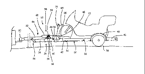
Referring to the accompanying figures there is illustrated a ground level
loading trailer generally indicated by reference numeral 10. The trailer 10 is
arranged
for connection to a towing vehicle in a transport position for rolling
movement in a
forward direction. The trailer 10 is particularly suited for being displaced
into a loading
position substantially at ground level for convenience in loading various
objects
thereon, for example for loading a motorcycle 12 as shown in the illustrated
embodiment.
The trailer 10 comprises a deck frame 14 including two side members
16 extending in a longitudinal direction along opposing sides of a rectangular
main
portion of the deck frame between a front end and a rear end thereof. The deck
frame
further includes a front member 18 comprising a rigid beam of rectangular
cross
section similar to the side members 16 so as to be fixed spanning
perpendicularly
between the two side members 16 at the front end thereof to form a generally U-
shaped configuration with the side member.
The deck frame further includes a deck surface 20 comprising a rigid
CA 02635886 2008-05-29
7
sheet which spans between the two side members 16 from the front end to the
rear
end of the main portion of the deck frame. The deck surface 20 is recessed in
elevation relative to the upper surface of the side member 16. A plurality of
floor
members 22 extend between the two side members 16 adjacent the bottom side
thereof to support the deck surface 20 spanning thereabove below the top side
of the
front member and the two side members 16. The deck surface 20 includes a ramp
edge 24 which is sloped downwardly and rearwardly from a rear edge of the
rigid
sheet forming the deck surface to a rear edge which is substantially coplanar
with a
bottom of the floor members 22 and the side members 16. The deck frame is thus
arranged for laying horizontally flat against the ground at ground level in a
loading
position so that various objects, for example a motorcycle 12 can be rolled
directly
onto the deck surface from the ground.
The deck frame 14 further includes a hitch support portion 26 which is
fixed onto the front member 18 to extend generally forward therefrom. The
hitch
support portion comprises primarily of a hitch support member 28 which is
centered in
a lateral direction between the two opposing sides of the deck frame to extend
forwardly in a generally common plane with the side members 16. The hitch
support
portion 26 of the deck frame further includes a pair of brace members 30
spanning
from the front end of the two side members 16 respectively, forwardly at an
inward
incline towards one another to be fixedly joined with the hitch support member
28
spaced forwardly of the front member 18 of the main portion of the deck frame
for
added structural support.
The trailer further includes a pivot frame 32 comprised of two side rails
34 which are parallel and spaced apart from one another so as to extend in a
longitudinal direction from a rear end to the front end of the main portion of
the deck
CA 02635886 2008-05-29
8
frame along outer sides of the two side members 16 of the deck frame
respectively in
a transport position of the trailer. The pivot frame further includes a
crossbar 36 fixed
between the two side rails 34 at the front ends thereof to form a generally U-
shaped
frame with the two side rails. The pivot frame is coupled at a rear end to the
rear end
of the deck frame 14 for relative pivotal movement about a first lateral axis
which is
oriented perpendicular to the forward direction and extends horizontally in a
lateral
direction. The pivot frame is coupled to the deck frame by hinging a rear end
of each
of the side rails 34 to the rear end of the corresponding side member 16 of
the deck
frame so that the pivot frame is pivotal between the transport position in
which the
pivot frame is substantially coplanar with the deck frame and the loading
position in
which the side rails 34 of the pivot frame extend upwardly and forwardly from
the rear
of the deck frame so that the forward ends of the pivot frame, which are
joined by the
crossbar 36, are spaced above the front end of the deck frame in the loading
position.
Two wheels are supported on the pivot frame at the outer sides of the
side rails at respective locations spaced forwardly from the pivotal
connection to the
side members of the deck frame. One wheel is supported on each of the side
rails 34
of the pivot frame so as to be arranged for rolling movement in the forward
direction at
a location which is closer to the rear end of the deck frame than the front
end while
being spaced forwardly from the rear end by an amount greater than the
diameter of
the wheels, in the order of twice the diameter of the wheels in the
illustrated
embodiment.
The wheels are supported for rotation about a common wheel axis
which is spaced forwardly of the first lateral axis of relative pivotal
movement between
the pivot frame and the deck frame. The wheels are arranged to remain engaged
with
the ground as the deck frame is displaced between the transport position and
the
CA 02635886 2008-05-29
9
loading position. When the deck frame is lowered, the front ends of the side
rails of
the pivot frame are displaced upwardly from a horizontal position so that the
wheels
act as fulcrum and the rear ends of the side rails are displaced downwardly to
be
located adjacent the ground in the loading position when the deck frame to
which the
rear ends of the side rails are coupled lays flat on the ground. Accordingly
the side
rails extend upwardly and forwardly from the rear of the deck frame in the
loading
position.
The pivot frame further includes two fenders 40 which extend
circumferentially about an upper portion of each wheel spaced radially upward
therefrom such that the forward and rear ends of the fenders are approximately
diametrically opposite one another with the wheel axle therebetween. A
plurality of
deck extension panels 42 are mounted to extend generally in the longitudinal
direction
from both front and rear sides of each fender in a generally common plane with
one
another and the two side rails of the pivot frame. The deck extension panels
42 span
laterally outward in the lateral direction from the side rails approximately a
width of the
fenders and the wheels at respective inner ends adjacent the fenders and are
reduced in lateral dimension as the panels extend outwardly to the respective
forward
and rearward ends of the pivot frame where the panels terminate.
A hitch frame 44 is pivotally coupled to the front end of the pivot frame
for relative pivotal movement about a second lateral axis also oriented
perpendicularly
to the forward direction to extend horizontally in a lateral direction
relative to the side
rails of the pivot frame. Mounting plates 46 are provided spanning opposing
ends of
the crossbar 36 of the pivot frame which project forwardly from the pivot
frame to
mount a base member 48 of the hitch frame extending therebetween. The base
member 48 accordingly extends laterally across the front of the pivot frame
crossbar
CA 02635886 2008-05-29
and is pivotally supported at opposing ends adjacent a bottom side thereof on
the
mounting plates 46 respectively for pivotal movement about the second lateral
axis.
The base member 48 accordingly spans the width of the pivot frame similarly to
the
crossbar.
5 The
hitch frame also includes a hitch arm 50 which is fixed mounted
centrally on the base member to project forwardly therefrom perpendicularly to
the
base member generally in the forward direction. The hitch arm is fixed to the
base
member for pivotal movement therewith about the second lateral axis. The hitch
arm
is arranged to extend above and along the top side of the hitch supporting
member 28
10 of
the deck frame in the transport position with the base member and the crossbar
being abutted alongside one another directly above the front member of the
deck
frame.
By pivotally supporting the base member 48 adjacent the bottom side
thereof, a top side of the base member is arranged for abutment with the front
side of
the crossbar when the hitch arm extends generally horizontally in common plane
with
the pivot frame so that the abutment between the base member and the crossbar
functions as a stop to prevent upwardly pivotal movement of the hitch arm
beyond a
horizontal orientation aligned in a common plane with the pivot frame in the
transport
position. The hitch arm however is freely pivotal downwardly relative to the
plane of
the side rails of the pivot frame so that when the side rails of the pivot
frame extend
upwardly and forwardly in the loading position, the hitch arm may extend
generally
forwardly through a range of upward and downward inclines with the rear end of
the
hitch am-i being spaced above the front end of the deck. Accordingly in the
loading
position with the deck frame positioned at ground level, the hitch arm may be
pivoted
into a downward and forward inclination so as to remain connected to a towing
vehicle
CA 02635886 2008-05-29
11
by a hitch connector 52 at the forward most end of the hitch arm.
Two mounts 54 are provided on the hitch supporting member 28 of the
deck frame at longitudinally spaced positions along the hitch supporting
member for
selective engagement with the hitch arm at spaced positions along the hitch
arm in
the transport position. Each mount 54 comprises a pair of parallel plates
mounted on
opposing sides of the hitch supporting member to extend generally upward
therefrom.
The plates are accordingly spaced apart so as to receive a portion of the
hitch arm
therebetween at each of the mounts 54. Cooperating apertures in the plates of
each
mount cooperate with the hitch arm to receive a suitable locking pin
therethrough in
the transport position which effectively locks the hitch supporting member of
the deck
frame to be horizontal and parallel with the hitch arm in the transport
position. The
pivotal coupling of the rear end of the hitch arm to the front end of the side
rails of the
pivot frame accordingly forces the pivot frame to be displaced downwardly at
the front
end thereof to remain engaged with the front end of the deck frame in the
transport
position.
A lift mechanism 56 is coupled between the rear of the hitch arm 44
which is in turn connected to the front end of the pivot frame and the front
of the main
portion of the deck frame at the hitch supporting member so that the lift
mechanism
56 operates to lift the front end of the deck frame relative to the front end
of the side
rails of the pivot frame and the rear end of the hitch arm pivotally coupled
thereto.
Lowering the front end of the pivot frame in turn causes the pivot frame to be
pivoted
about the wheels which function as a fulcrum to lift the rear ends of the side
rails of
the pivot frame and the deck frame into the transport position from the
loading
position.
The lift mechanism comprises a winch including a drum 58 onto which a
CA 02635886 2008-05-29
12
cable 60 is arranged to be wound by a suitable electric motor 62. The cable 60
extends from the drum supported on the rear end of the hitch arm downwardly
through a pulley 64 rotatably supported at a rear end of the hitch supporting
member
of the deck frame. The end of the cable 60 is anchored on the hitch arm
adjacent the
mounting of the drum 58.
Operating the winch in a winding direction causes the cable between the
hitch arm and the deck frame to be shortened so that the front end of the deck
frame
is raised while the front end of the side rails of the pivot frame are
simultaneously
lowered from the loading position to transport position.
Operating the winch in an opposing unwinding direction causes the
cable to be lengthened for effectively lowering the deck frame relative to the
front
ends of the side rails of the pivot frame towards the loading position. By
lowering the
deck frame relative to the front ends of the side rails, the front ends of the
side rails
are permitted to in turn be displaced upwardly so that the lowering of the
rear ends of
the side rails simultaneously lowers the rear end of the deck frame. The
electric motor
62 is arranged to be driven by power from a battery 64 supported on the pivot
frame
at the front crossbar with the battery 64 being coupled through towing
connection to
the towing vehicle for recharging of the battery.
In the illustrated embodiment for supporting a motorcycle, the deck
surface 20 of the deck frame includes a front wheel support 68 comprising a
pair of
parallel plates arranged to receive the front wheel of the motorcycle
therebetween for
securement during transport. The deck surface has a length and width which
corresponds to at least a length and width of a typically motorcycle to
adequately
support the motorcycle thereon.
In the loading position, the deck frame lays flat on the ground with the
CA 02635886 2008-05-29
13
hitch arm and the front end of the pivot frame being freely supported above
the front
end of the deck frame so that that the front end of the deck frame is
unsupported on
the ground. The weight of the deck frame allows the rear end of the deck frame
to
remain engaged upon the ground in the loading position while causing the rear
ends
of the side rails of the pivot frame to be similarly displaced downwardly
against the
ground so that the wheels supported on the side rails act as fulcrum to cause
the side
rails to extend upwardly and forwardly to the front ends thereof spaced above
the
deck frame upon which the rear end of the hitch arm is supported. The free
pivotal
connection of the rear end of the hitch arm on the front end of the side rails
of the
pivot frame permits the hitch connector at the front end of the hitch arm to
be pivoted
downward relative to the pivot frame so that it may remain engaged in
connection with
a towing vehicle in the loading position.
Once the deck frame has been loaded with cargo, for example a
motorcycle 12, the lift mechanism is operated to raise the front end of the
deck frame
relative to the ground and the front ends of the side rails of the pivot frame
so that the
forward end of the hitch supporting member comes into engagement with the
hitch
arm at a location spaced between the hitch connector and the rear end
pivotally
coupled on the pivot frame. Continued lifting of the front end of the deck
frame relative
to the front end of the side rails of the pivot frame causes the hitch arm and
the side
rails of the pivot frame to come into horizontal alignment with one another in
a
generally common plane after which further upward pivotal movement of the
hitch arm
relative to the pivot frame is prevented by abutting inter-engagement between
the
base member of the hitch frame and the front crossbar of the pivot frame. Once
the
hitch arm and the pivot frame lay flat against the deck frame in a horizontal
orientation
therewith, suitable locking pins are inserted through the cooperating
apertures in the
CA 02635886 2014-02-13
14
mounts 54 so that the deck frame can be rigidly secured to the hitch arm at
longitudinally spaced positions therealong. The hitch arm and the pivot frame
are
accordingly arranged to be secured in the transport position relative to the
deck frame
independently of the lift mechanism so that once locking pins fixedly secure
the hitch
supporting member of the deck frame to the hitch arm, any failure of the
lifting
mechanism will not cause failure of the trailer to fall back into the loading
position.
A jack stand 70 is provided for selective mounting on the hitch arm for
supporting the hitch arm spaced above the ground in the transport position for
storage
when disconnected from a towing vehicle. When not is use, the jack stand can
be
selectively coupled to the front wheel support 68 of the deck frame.