Language selection

Search

Patent 2636019 Summary

Third-party information liability

Some of the information on this Web page has been provided by external sources. The Government of Canada is not responsible for the accuracy, reliability or currency of the information supplied by external sources. Users wishing to rely upon this information should consult directly with the source of the information. Content provided by external sources is not subject to official languages, privacy and accessibility requirements.

Claims and Abstract availability

Any discrepancies in the text and image of the Claims and Abstract are due to differing posting times. Text of the Claims and Abstract are posted:

  • At the time the application is open to public inspection;
  • At the time of issue of the patent (grant).
(12) Patent Application: (11) CA 2636019
(54) English Title: CONTACT WITH IMPROVED RETENTION MEMBER
(54) French Title: CONTACT AVEC ELEMENT DE RETENTION AMELIORE
Status: Deemed Abandoned and Beyond the Period of Reinstatement - Pending Response to Notice of Disregarded Communication
Bibliographic Data
(51) International Patent Classification (IPC):
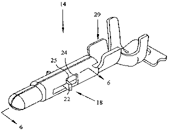
  • H01R 13/432 (2006.01)
(72) Inventors :
  • FABIAN, DAVID JAMES (United States of America)
  • DIEMER, DONALD ALAN (United States of America)
  • BAUGHN, DONALD MICHAEL (United States of America)
(73) Owners :
  • TYCO ELECTRONICS CORPORATION
(71) Applicants :
  • TYCO ELECTRONICS CORPORATION (United States of America)
(74) Agent: SMART & BIGGAR LP
(74) Associate agent:
(45) Issued:
(86) PCT Filing Date: 2007-01-31
(87) Open to Public Inspection: 2007-08-09
Examination requested: 2008-07-10
Availability of licence: N/A
Dedicated to the Public: N/A
(25) Language of filing: English

Patent Cooperation Treaty (PCT): Yes
(86) PCT Filing Number: PCT/US2007/002715
(87) International Publication Number: US2007002715
(85) National Entry: 2008-07-10

(30) Application Priority Data:
Application No. Country/Territory Date
60/763,636 (United States of America) 2006-01-31

Abstracts

English Abstract


An electrical terminal (2) includes a body (4) having a locking member (6) and
the locking member extends through an aperture (10) and backs up to the body.
The locking member is configured to abut the housing, in one embodiment the
locking member is disposed through the channel defined by the body while
another embodiment a plurality of locking members are at least partially
disposed within the channel . Preferably, the locking member is stamped out
from the body. In a variation the body has a projection which can abut the
housing to lock the body into the housing.


French Abstract

La présente invention concerne une borne électrique qui comprend un élément de verrouillage, qui se prolonge à travers une ouverture et soutient le corps. L'élément de verrouillage est configuré pour buter contre le logement. Dans un mode de réalisation, l'élément de verrouillage est disposé à travers le canal défini par le corps tandis que dans un autre mode de réalisation, une pluralité d'éléments de verrouillage est au moins partiellement disposée dans le canal. De préférence, l'élément de verrouillage est détaché du corps. Dans une variation, le corps possède une projection qui peut buter sur le logement pour verrouiller le corps dans le logement.

Claims

Note: Claims are shown in the official language in which they were submitted.

What is Claimed is:
1. An electrical terminal, comprising:
a body having an aperture; and
a locking member extending from said body and at least partially out of
said aperture, configured to back up to said body.
2. The electrical terminal of claim 1, wherein said locking member is
configured to be biased by a housing.
3. The electrical terminal of claim 1, wherein said locking member is
configured to be biased from a first position to a second position toward
center
of said body during said body insertion into a housing, and to return to a
third
position away from the center of said body upon further insertion into the
housing.
4. The electrical terminal of claim 1, wherein said locking member extends
through said aperture.
5. The electrical terminal of claim 1, wherein said body further comprises a
plurality of said locking members, a plurality of point of connections, a
plurality
of said apertures and a plurality of distal ends.
6. The electrical terminal of claim 5, wherein at least one of said point of
connections is configured to extend away from adjacent side of said body, at
least one of said distal ends configured to extend toward the adjacent side of
said body, said at least one of said point of connections associated to said
body,
said at least one of said distal ends having a greater width in a
circumferential
-7-

direction than said at least one of said point of connections, said at least
one of
said distal ends configured to back up to said body during said body insertion
into the housing.
7. The electrical terminal of claim 5, wherein said plurality of said locking
members comprise a stopping means to prevent further insertion of the
electrical
terminal.
8. The electrical terminal of claim 5, wherein at least one of said distal
ends
is disposed in a channel of said body through at least one of said apertures.
9. The electrical terminal of claim 5, wherein at least one of said apertures
is
defined by a cutout of said at least one of said point of connections and at
least
one of said distal ends.
10. The electrical terminal of claim 1, wherein said body includes a
projection, said projection configured to abut a shoulder of the housing
during
said body insertion into the housing to thereby prevent further insertion of
said
body into the housing beyond a locking position.
-8-

Description

Note: Descriptions are shown in the official language in which they were submitted.


CA 02636019 2008-07-10
WO 2007/089879 PCT/US2007/002715
CONTACT WITH IMPROVED RETENTION MEMBER
[0001] An improved electrical terminal and more particularly to an
improved locking feature for the retention of the electrical terminal within a
housing is described.
[0002) Several methods exist for retaining an electrical terminal within a
housing. In various applications of electrical connectors, devices are
utilized to
lock the terminals in place and to assure that they are in proper position
within
the electrical connector.
100031 Certain electrical connectors are provided with housings having
cavities extending therethrough for receiving electrical terminals. One such
method of retention, is to provide a stamped-out lance from the electrical
terminal body which abuts a shoulder within the housing.
[0004] The objects of the invention are therefore to improve upon these
known connection systems.
[0005] The objects of the invention have been accomplished by providing
an electrical terminal comprising a body including a locking portion
configured
to lock the body in a housing. The body includes an aperture extending at
least
partially through the body. The locking portion defines a locking shoulder and
the locking portion is positioned through the aperture. The locking shoulder
is
backed up by the body. Preferably, the body comprises a plurality of the
locking portions and a plurality of apertures.
[0006] In another embodiment, an electrical terminal comprises a body
having an aperture and a locking member extending from the body and at least
-1-

CA 02636019 2008-07-10
WO 2007/089879 PCT/US2007/002715
partially out of the aperture where the locking member is configured to back
up
to the body. The locking member is configured to be biased by a housing. The
locking member is configured to be biased from a first position to a second
position which is toward the center of the body during insertion of the body
into
a housing, and to return to a third position away from the center of the body
upon further insertion into the housing. The locking member extends through
the aperture and backs up to the body. The locking member is an arch and
provides a member to abut the housing. The electrical terminal cannot freely
move in a longitudinal direction relative to the housing because of the
locking
member abutting the housing.
[0007] The body includes a longitudinal seam extending along a length of
the body. The arch may be transverse to the seam. The aperture is located
across the body from where the locking member associates with the body.
[00081 In yet another embodiment, the body further comprises a plurality
of locking members, a plurality of point of connections, a plurality of
apertures
and a plurality of distal ends. At least one of the point of connections is
configured to extend away from an adjacent side of the body, at least one of
the
distal ends configured to extend toward the adjacent side of the body. At
least
one of the distal ends has a greater width in a circumferential direction than
at
least one of the point of connections. In a variation at least one of the
distal
ends is configured to back up to the body during the body insertion into the
housing. The electrical terminal cannot freely move in a longitudinal
direction
relative to the housing because of the locking member abutting the housing. In
a variation at least one of the distal ends is disposed in a channel of the
body
through at least one of the apertures. In another variation at least one of
the
distal ends is not disposed in a channel of the body through at least one of
the
-2-

CA 02636019 2008-07-10
WO 2007/089879 PCT/US2007/002715
apertures. In a separate variation at least one of the apertures is defined by
a
cutout of a point of connections and at least one of the distal ends.
[0009] The body includes a projection where the projection is configured
to abut a shoulder of the housing during the body insertion into the housing
to
thereby prevent further insertion of the body into the housing beyond a
locking
position. In a variation the projection is a rib where the rib is
circumferentially
disposed around the body.
[0010] Figure 1 is a perspective view showing an embodiment of the
electrical terminal of the present invention;
[0011] Figure 2 is a longitudinal cross-sectional view through the terminal
of Figure 1;
[0012] Figure 3 shows the terminal of Figure 1 with an alternative
projection;
[0013] Figure 4 is a perspective view showing a second embodiment of
the electrical terminal of the present invention;
[0014] Figure 5 is a perspective view similar to that of Figure 4, with a
wire crimp as the connection end;
[0015] Figure 6 is a longitudinal cross-sectional of the electrical terminal
through lines 6-6 of Figure 5;
[0016] Figure 7 shows a portion of the stamped blank of the electrical
terminal of Figure 5;
[0017] Figure 8 shows the terminal of Figure 5 and 6 with the locking
members moved to their fully inward position;
-3-

CA 02636019 2008-07-10
WO 2007/089879 PCT/US2007/002715
[0018] Figure 9 shows the terminal of Figure 1 shown poised for receipt
within a connector housing; and
[0019] Figure 10 shows the configuration of Figure 9, in a fully locked
position.
[0020] With reference first to Figure 1, an electrical terminal is shown at 2,
having a body 4, locking member 6, defining locking shoulder 8 extending
through aperture 10. Locking member 6 may be a cut out or a stamp out from
body 4. Locking member 6 may be resiliently biased into an arch or beam
structure. Locking member 6 is shown as formed to extend through aperture 10.
As best shown in Figure 2, locking shoulder 8 is positioned adjacent to a
forward edge 11 of body 4 which defines aperture 10.
[0021] As shown in Figure 1, terminal 2 is stamped and formed from a flat
blank material, where the flat blank is roll formed into a pin configuration,
and
where the side edges of the blank are formed into an abutting longitudinal
seam
34. Also as shown, locking member 6 is stamped from the blank which forms
an opening in body 4, and locking member 6 is thereafter formed to extend
through opening 10.
[0022] Body 4 further includes projection 12. As shown in Figure 1,
projection 12 is shown as a bulbous form, but it should be appreciated that
the
projection could be a tab cut out or stamped out from body 4. For example, and
with reference to Figure 3, the projection may be in the form of a tab 12'
stamped from body 4.
[0023] With reference again to Figure 1, body 4 further includes contact
gripping element 28, aperture 30, channel 32 and seam 34. The contact
-4-

CA 02636019 2008-07-10
WO 2007/089879 PCT/US2007/002715
gripping element 28 defines a wire trap for contacting a bare conductor of an
insulated wire.
[0024] With reference now to Figures 4 -6, terminal is shown at 14 having
body 16 having a plurality of locking members 18 having a plurality of beam
sections 20 and a plurality of locking ends 22, extending through a like
plurality
of apertures 24. Beam sections 20 and locking ends 22, may be cut outs or
stamp outs from body 16. As shown in Figure 4, terminal 14 includes a contact
gripping member 28, whereas in Figure 5, the terminal 14 includes a wire crimp
connection 29.
[0025] With respect now to Figure 7, the pin end portion of the terminal
14 is shown in the flat blank condition. As shown, the beam sections 20 and
locking ends 22 are stamped from the body portion 16 prior to the forming. It
should be appreciated from viewing Figure 6 that the locking ends 22 are wider
than the beam section 20 and thus when stamped and formed into the
configuration of Figure 5, locking ends are positioned adjacent to a forward
edge 25 of stamped aperture 24.
[0026] More particularly, the locking sections are formed by stretching
and compressing the beam sections 20, such that the sections 20 are longer
than
the apertures through which they were stamped. Thus when formed, and as best
shown in Figures 5 and 6, the locking ends 22 are positioned adjacent to edges
25 which help to reinforce or back up the rigidity in the locking members 18.
[0027] At the same time, the sections are formed such that they contact
each other when biased inwardly. As shown in Figure 8, the locking ends are
moved inwardly to the position where beam sections are touching. However,
the beam sections bottom out before the locking ends extend through their
respective aperture 24. This prevents the locking ends from getting caught
-5-

CA 02636019 2008-07-10
WO 2007/089879 PCT/US2007/002715
inside of the terminal body. As the beam sections contact each other, spring
back is provided to the beam sections, forcing them back through the apertures
24 after compression. This also prevents undue stress at the root of the
connection point of the beam sections 20 and the body 16.
[0028] With the individual components as previously described, the
function of one embodiment of electrical terminal 2 will now be described in
greater detail. The following described function is equally applicable to
other
disclosed embodiments.
[0029] As best shown in Figure 9, a connector housing 36 is shown having
a cavity 37 into which either of terminals 2 or 14 can be positioned. Housing
36
has a first shoulder 38 and second shoulder 40. With respect to Figure 10,
terminal2 is shown inserted into housing 36, with locking shoulder 8 (Figure
2)
abutting first shoulder 38, and with projection 12 abutting shoulder 40.
Shoulder 8 would be rigidified by edge 11, reinforcing the locking engagement
of terminal2 to housing 36.
[0030] It should be appreciated that the embodiment of Figures 4-8 would
be locked into housing 37 in much the same way with locking ends 22
positioned adj acent housing surface 38, and with proj ections 26 adj acent to
surface 40. While not shown, it should be appreciated that locking members
could alternatively be formed with the beams 20 extending outside of the body
portion, and with locking ends projecting from outside-in, forming an
alternative locking shoulder.
-6-

Representative Drawing
A single figure which represents the drawing illustrating the invention.
Administrative Status

2024-08-01:As part of the Next Generation Patents (NGP) transition, the Canadian Patents Database (CPD) now contains a more detailed Event History, which replicates the Event Log of our new back-office solution.

Please note that "Inactive:" events refers to events no longer in use in our new back-office solution.

For a clearer understanding of the status of the application/patent presented on this page, the site Disclaimer , as well as the definitions for Patent , Event History , Maintenance Fee  and Payment History  should be consulted.

Event History

Description Date
Application Not Reinstated by Deadline 2011-01-31
Time Limit for Reversal Expired 2011-01-31
Inactive: Abandoned - No reply to s.30(2) Rules requisition 2010-07-05
Deemed Abandoned - Failure to Respond to Maintenance Fee Notice 2010-02-01
Inactive: S.30(2) Rules - Examiner requisition 2010-01-04
Inactive: Office letter 2009-03-25
Letter Sent 2009-03-16
Inactive: Office letter 2009-03-16
Letter Sent 2009-03-16
Inactive: Single transfer 2009-01-21
Correct Applicant Request Received 2008-11-07
Inactive: Cover page published 2008-11-03
Letter Sent 2008-10-20
Inactive: Acknowledgment of national entry - RFE 2008-10-20
Inactive: First IPC assigned 2008-08-21
Application Received - PCT 2008-08-20
National Entry Requirements Determined Compliant 2008-07-10
Request for Examination Requirements Determined Compliant 2008-07-10
All Requirements for Examination Determined Compliant 2008-07-10
Application Published (Open to Public Inspection) 2007-08-09

Abandonment History

Abandonment Date Reason Reinstatement Date
2010-02-01

Maintenance Fee

The last payment was received on 2009-01-02

Note : If the full payment has not been received on or before the date indicated, a further fee may be required which may be one of the following

  • the reinstatement fee;
  • the late payment fee; or
  • additional fee to reverse deemed expiry.

Patent fees are adjusted on the 1st of January every year. The amounts above are the current amounts if received by December 31 of the current year.
Please refer to the CIPO Patent Fees web page to see all current fee amounts.

Fee History

Fee Type Anniversary Year Due Date Paid Date
Request for examination - standard 2008-07-10
Basic national fee - standard 2008-07-10
MF (application, 2nd anniv.) - standard 02 2009-02-02 2009-01-02
Registration of a document 2009-01-21
Owners on Record

Note: Records showing the ownership history in alphabetical order.

Current Owners on Record
TYCO ELECTRONICS CORPORATION
Past Owners on Record
DAVID JAMES FABIAN
DONALD ALAN DIEMER
DONALD MICHAEL BAUGHN
Past Owners that do not appear in the "Owners on Record" listing will appear in other documentation within the application.
Documents

To view selected files, please enter reCAPTCHA code :


To view images, click a link in the Document Description column. To download the documents, select one or more checkboxes in the first column and then click the "Download Selected in PDF format (Zip Archive)" or the "Download Selected as Single PDF" button.

List of published and non-published patent-specific documents on the CPD .

If you have any difficulty accessing content, you can call the Client Service Centre at 1-866-997-1936 or send them an e-mail at CIPO Client Service Centre.


Document
Description 
Date
(yyyy-mm-dd) 
Number of pages   Size of Image (KB) 
Description 2008-07-09 6 290
Abstract 2008-07-09 1 63
Claims 2008-07-09 2 69
Drawings 2008-07-09 5 86
Representative drawing 2008-07-09 1 7
Acknowledgement of Request for Examination 2008-10-19 1 175
Reminder of maintenance fee due 2008-10-19 1 111
Notice of National Entry 2008-10-19 1 202
Courtesy - Certificate of registration (related document(s)) 2009-03-15 1 102
Courtesy - Abandonment Letter (Maintenance Fee) 2010-03-28 1 172
Courtesy - Abandonment Letter (R30(2)) 2010-09-26 1 164
PCT 2008-07-09 4 154
Correspondence 2008-11-06 3 126
Correspondence 2009-03-24 1 15
PCT 2010-07-19 2 95