Note: Descriptions are shown in the official language in which they were submitted.
CA 02636048 2013-10-04
COLOSTOMY BAG CLEANING SYSTEM
BACKGROUND OF THE INVENTION
[0001] A colostomy is a surgical procedure in which the colon or a
portion thereof is
removed and the digestive tract is attached to an opening created in the
abdominal wall, thereby,
allowing digested waste to pass through the abdomen. Typically, the waste is
then collected by
an impervious bag that is secured over the opening. The opening that results
from a colonectomy
is known as an "ostomy' or a "stoma," and the impervious bag that collects the
digestive waste is
known as a colostomy bag.
[0002] An individual who has had a colostomy must typically remove and
empty the
colostomy bag several times a day, and must irrigate the ostomy at least every
other day to
maintain good health and sanitation. An ostomy is irrigated by applying
flowing water into the
ostomy and then allowing the water to drain.
[0003] Examples of ostomy irrigating devices in the prior art or
cleansing systems are
provided by U.S. Patent Application Publication No. US2003/0229324, which
features a closed
drainage system that eliminates the necessity to stand over a toilet, as it
has its own collection
system, but it is a difficult system to use and almost requires the person to
be lying down as
illustrated in Figure 1 for any satisfactory use. U.S. Patent No. 6,408,861
illustrates a urine bag
cleaning manifold, which is a very complicated system associated with a shower
in a bathtub,
and again, is difficult to operate and very elaborate in design. Patent No.
5,454,389 teaches an
ostomy bag cleaning device that incorporates a mechanism for introducing water
into a
colostomy bag and then evacuate the waste material into a storage chamber.
This device is
cumbersome to use and does not provide for a simple cleaning of the colostomy
bag without
removal form the person.
100041 Patent Nos. 5,096,503 and 4,194,506 both teach the general concept
of insertion
rods being inserted from the bottom of the colostomy bag up into the bag
itself, and in both of
these systems it's awkward to have to insert a rod up through. the bottom of
the colostomy bag
with whatever drippings and materials that would be coming out, and this is
not a satisfactory
technique for cleaning the colostomy bag while having the bag still maintained
on the person. A
similar patent is 5,738,668, which again inserts a probe up into the bag for
cleaning, and again
- 1 -
CA 02636048 2013-10-04
the same problems are inherent. Patent No. 6,532,971 teaches a sanitary pouch
washer that is
designed for simultaneously cleaning the inside and outside of the colostomy
bag and is a
complicated mechanism and, again, is done with the colostomy bag removed from
the person.
U.S. Patent No. 6,224,581 teaches a colostomy bag cleaning appliance having a
mounting plate
and, again, this is a cleaning method with the bag removed form the person and
creates
significant complications in achieving the cleaning in a simple and effective
manner.
SUMMARY OF THE INVENTION
[0005] The present invention is a closed draining system for externally
cleansing
ostomies and cleaning colostomy bags utilizing a manifold physically located
near the top of the
bag that provides a stream of water in a sprayed fashion into the top of the
bag for internally
cleaning the bag and simultaneously cleaning the exposed surfaces of the
ostomy, and with the
amount of water or cleaning solution added being controlled by the user, the
bag still being in
place on the person, and the flow from the bag coming out the bottom with the
normal opening
type bags available today. The cleansing system is an integral part of the
pouch.
[0006] Accordingly, it is a principal object of the invention to
facilitate cleaning of the
colostomy bag and simultaneously cleaning the exposed surfaces of the ostomy
by providing a
manifold near the top of the colostomy bag that is connected to a source of
water under some
pressure that can then controllably sprinkle and/or spray water into the
colostomy bag for
cleaning of the bag and the ostomy, with the flow then directed out the bottom
of the normal
opening-type colostomy bags. During cleansing, the person still has the
colostomy bag attached
to their body, and the cleaning takes place in association with drainage into
a toilet or other
suitable drainage facility. This system may be an integral part of the pouch
to allow convenient
use at the discretion of the user by simply applying water under pressure to
the inlet port while
sitting on a commode to receive dispelled waste.
[0007] The invention provides the ability for cleaning of the colostomy
bag with the bag
still attached to the body of the person, and it can be done quickly and very
effectively on a
regular basis during the day or any desired time or times.
- 2 -
CA 02636048 2013-10-04
[0008] In an embodiment of the invention, the manifold is formed in
conjunction with a
standard colostomy bag flange, which is a flanged ring with adhesive backing
that is typically
secured to the abdomen of a person with an ostomy. The flange allows a
colostomy bag to be
easily attached and detached. The colostomy bag attaches to the flanged ring
much like some
plastic lids attach to a corresponding plastic bowl, i.e., the colostomy bag
and flange snap
together to form an airtight seal. Consequently, an external cleansing system
that uses the same
flanged ring is also easily attached and detached and, further, does not
necessitate the removal of
the bag from the person for the cleansing of the external surfaces of the
stoma. If desired, the
cleansing system may include both an upper plenum for dispersing water or a
cleansing solution
throughout the bag, and a cleansing system formed about the ostomy opening.
[0009] The invention provides improved elements and arrangement for the
purposes
described, and yet is inexpensive to manufacture, dependable and fully
effective in
accomplishing its intended purposes.
[0010] These and other aspects of the present invention will become
readily apparent
upon further review of the following specifications and drawings.
BRIEF DESCRIPTION OF THE DRAWINGS
[0011] Figure 1 is a perspective view of the colostomy bag utilizing a
manifold around
the flanged opening on the bag itself, which then attaches to the flanged
fitting positioned on the
body of the person, and snaps together to form a fluid-tight seal between the
bag and the person;
[0012] Figure 2 is a perspective illustration showing a stick figure
utilizing the invention
by irrigating and flushing the colostomy bag by controlling a valve from the
water supply to the
toilet with the bottom of the colostomy bag open and flow taking place from
the manifold
through the bag and into the toilet;
[0013] Figure 3 is a perspective illustration of the manifold associated
with the flanged
ring and adhesive backing for attachment to a person, for engaging in a fluid-
tight relationship
with the fitting on the colostomy bag, with the colostomy bag itself removed
from the Figure to
depict the mated relationship between the flanged ring attached to the person
and the fitting on
the colostomy bag;
- 3 -
CA 02636048 2013-10-04
[0014] Figure 4 illustrates a colostomy bag with the manifold positioned
around the top
of the formed snap connection for the bag itself and water inlet being
provided to the manifold
around the top of the bag connection opening;
[0015] Figure 5 is a cross-sectional illustration of a modified colostomy
bag, having a
manifold heat-seal formed into the material itself and at the very top access
opening into the bag
well above the stoma opening;
[0016] Figure 6 is a top-plan view of a colostomy bag showing some hook
and loopstrips
along the bag, to be folded up in half and held in that position;
[0017] Figure 7 is the bag shown in Figure 6 folded-up, reduced in half
its length in the
position where the bag is held in the folded position by the hook and loop
strips;
[0018] Figure 8 is a cross-sectional illustration of the bag of Figure 5
taken on line 8-8 of
Figure 5;
[0019] Figure 9 is a broken-away cross-sectional view of the bag of
Figure 5 taken on
line 9-9 of Figure 5;
[0020] Figure 10 is a plan view of an embodiment of a colostomy bag,
having a cleansing
system integrally formed therein as an upper manifold formed into the material
itself such as by
dot welds, adjacent the very top access opening of the bag, with a modulated
array turbulence
producing structures and openings arranged throughout the integral manifold;
[0021] Figure 11 is a plan view of a further embodiment of a colostomy
bag, having a
manifold integrally formed into the material itself adjacent a top access
opening of the bag; and
[0022] Figure 12 is a perspective view of the colostomy bag and cleaning
system for
cleaning of the colostomy bag in an alternate embodiment of the invention.
DESCRIPTION OF THE INVENTION
[0023] Referring now to Figure 1 of the drawings, the numeral 10
indicates a colostomy
bag, which has an opening 12 that is surrounded by a plastic ring 14 and
attached in a fluid-tight
fashion to the bag 10 by suitable means, such as adhesively or by other
suitable known means.
- 4 -
CA 02636048 2013-10-04
The ring 14 is formed with a flange that is designed to mate with a similarly
formed ring and
flange 14A on the person mounted colostomy bag attachment patch 16. The patch
16 is attached
by pressure-sensitive adhesive on the back of the patch itself and the
respective ring flanges 14
and 14A when snapped together form a fluid-tight seal between the ostomy 18
and the interior of
the colostomy bag 10.
[0024] A cleansing system according to an embodiment of the invention is
provided by a
circular manifold, generally indicated by numeral 20, which is preferably a
soft plastic and
encircles the interior of the opening 12 into the colostomy bag 10. A
plurality of small holes 22
around the perimeter of the manifold 20 are provided to allow the passage of
spray in multiple
and random directions of water pressure introduced through an access tube 24
that is connected
to a water source not shown via fitting 26. Alternatively, the manifold 20 may
be integrally
formed around opening 12, such as by heat-sealing or the like.
[0025] The colostomy bag 10 is designed to be opened at the bottom end,
generally
identified by numeral 30. For use, this bottom opening is rolled up and
retained in a position to
close the opening, such as by a sealing procedure utilizing hook and loop
material indicated by
the loop material 32 and the hook material 34. It should be understood that
when this bottom end
30 is folded up and the hook and loop attachment is in place, the bag is
sealed at the bottom. For
selective cleansing of the bag and exposed portion of the ostomy, the bag is
opened and
positioned over the toilet so that irrigation cleansing water or solution
passing through the
manifold 20 and orifices 22 will flow down through the bag and out the bottom
opening 30 and
into the toilet or the like, as is shown in more detail in Figure 2 of the
drawings.
[0026] Referring now to Figure 2, this illustrates a normal toilet
indicated generally by
numeral 40, on which the individual will normally sit toward the back on the
toilet seat to
operate the invention. A flexible water or supply hose 42 is selectively
connected to the fitting 26
to provide water under pressure through the conduit 24 and to the manifold 20
for spray out the
orifices 22. The water source is by a fitting indicated generally by numeral
44 that fits into the
normal water supply tubing to the toilet, indicated by numeral 46, and has the
ability to control
the amount of flow by a valve, indicated by numeral 48, associated with the
conduit 42.
- 5 -
CA 02636048 2013-10-04
[0027] Thus, with reference to Figure 2, it can be understood that the
individual sits on
the toilet seat, connects the conduit 42 to fitting 26 and then, by
adjustively controlling the valve
48, provides a sufficient amount of water under pressure into the manifold to
cause a flow to
cleanse the ostomy 18, and to provide a cleansing action within the colostomy
bag 10, with the
residue dripping out at the bottom into the toilet as shown generally by
numeral 50.
[0028] Referring now to Figure 3, this shows an embodiment where the
manifold,
identified generally as numeral 20a is associated with the ring 14A of the
patch 16 that is
attached to the skin of the person over the ostomy opening 18. In this
embodiment, the manifold
20a includes an access fitting 24A selectively connected to the water line 42
so that regulated
water under pressure provides the spray through orifices 22a illustrated
generally by the numeral
60.
[0029] Referring now to Figure 4, this shows an embodiment of the
invention where the
manifold, indicated generally by numeral 20b, is positioned above the opening
12 in the
colostomy bag 10. A similar water inlet or access fitting 24b may be utilized
in this embodiment.
In this embodiment, the manifold 20b may be positioned adjacent the top of bag
10 to disperse
water or cleaning fluid under pressure throughout the bag 10 for quick and
effective cleaning of
bag 10. The spray from the plural outlets formed in manifold 20b also will
flow over and around
exposed portions of the ostomy for cleansing thereof. The upper manifold 20b
may be used alone
or with a manifold positioned about the ostomy opening if desired.
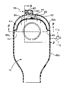
[0030] An alternate embodiment of an upper manifold is shown in Figure 5.
More
particularly, the manifold in Figure 5 is integrally formed in bag 10 by heat-
sealing the bag 10
along the line shown generally by numeral 80, which may extend from the edge
of the bag as
shown on the left side at 82 and around below the bottom of the top of the bag
and over to the
right side, indicated by numeral 84. The sealed line 80 may mirror the shape
of the top edge of
the bag to form a uniformly dimensioned manifold across the entire top of the
bag 10. The
plurality of openings 86 are provided through the heat-sealed portion 80, and
this then provides
for the random and multi-directed flow of water sprayed from the manifold
after being supplied
under pressure into the manifold from the supply opening in the direction of
arrow 88. The
access opening into the bag is indicated generally by numeral 90, is
integrally formed in the bag
10, and may include a one-way valve 92 that prevents back-flow up through the
opening 90 in
- 6 -
CA 02636048 2013-10-04
case the bag is squeezed or actuated through the force of fluid back up
through the opening 90 in
the bag. There may also be a divider indicated generally by numeral 94 that is
part of the heat-
formed portion of the manifold, which acts to direct the water flow entering
through opening 90
in opposite directions in the manifold around to the right and the left sides
of the bag as is
indicated by the water flow arrows indicated generally by numeral 96.
[0031] Thus, it should be understood in the embodiment of Figure 5 that
the water flows
in the direction indicated by arrow 88 through the one-way valve 92 and into
the manifold
formed by the heat-sealed line 80 and is directed substantially equally right
and left by the
divider 94 and then flows through the multiple openings 86 formed in the
manifold, as indicated
by the water flow by numeral 96. The plurality of openings 86 provide for
dispersement of water
or cleansing solution from the manifold throughout the bag 10, forming sheets
and sprays of
water in random directions from the very top of the colostomy bag including
down over the
stoma opening and then as it drains out through the bottom opening as
described previously.
Also note the openings 86a and 86b immediately adjacent the outer edge of the
bag that send a
water spray down the inside edges of the bag for better cleaning of these
surfaces.
[0032] Thus, it is seen in Figure 5 and as also shown in the cross-
sectional configurations
of Figures 8 and 9 that the manifold is enhanced and enlarged, while being
easily manufactured
integral to bag 10 by the heat-sealed line 80 adjacent the top of the bag. The
random directed
openings 86 provide for quick and efficient cleaning of the entire bag 10. It
should be understood
that the bag 10 can be formed from two similarly shaped essentially flat
flexible pieces of
polymer material that are heat sealed at the periphery in a heat-sealed line
80a as seen in Figures
and 8.
[0033] Figure 9 illustrates the cross-sectional portion of the bag of
Figure 5 taken on line
9-9 and it is depicted in the mode where there is water under pressure within
the manifold to
form a tubular configuration in the manifold itself as it is pressurized by
the water entering in the
direction of arrow 88 as shown in Figure 5.
[0034] Figure 8 shows the multiple openings 86 that are formed by the
heat-seal across
the manifold-forming heat-seal line 80, as shown in Figure 5.
- 7 -
CA 02636048 2013-10-04
[0035] Figures 6 and 7 shown hook and loop attachments 100 and 102, which
allow the
bag 10 to be folded from the position shown in Figure 6 as indicated by the
arrow 104 to the
half-position shown in Figure 7. This is convenient in certain times when the
bag is not really
full to allow a person to have a smaller bag than the full length bag of
Figure 6, and it greatly
facilitates keeping the bag from interrupting sleeping because of the smaller
size.
[0036] Thus, it should be understood that the bag and cleansing system
according to the
invention is very simply and cost effectively made, with the embodiments using
an integrated
manifold or manifolds further enhancing these attributes. In the embodiment of
Figure 5, the
heat-seal line 80 may be formed in the bag according to standard heat-seal
procedures while
simultaneously forming the openings 86 so that there will be a random and
plentiful flow, much
like a shower, from the openings and the water under pressure being applied
through the supply
opening 90 into the top of the manifold formed by the heat-sealed line 80.
[0037] Thus, it should be fully understood that Figures 5, 8 and 9 show
the heat-sealed
pouch configuration consisting of two chambers separated by a heat-sealed
septum, line 80,
containing a number of communication ports 86 connecting the two chambers. The
upper
chamber (or plenum) being the smaller of the two, with the system for being
connected to an
external water supply also integrated therewith. The lower chamber is the
larger of the two, with
the system for opening the bottom of the bag to accommodate the removal of its
contents during
cleansing. The communication ports 86 connecting the two chambers are
strategically positioned
to distribute the water that enters through the smaller, or upper, chamber in
a manner that
thoroughly cleanses the complete interior of the larger (or lower) chamber. It
will also
thoroughly cleanse around the stoma opening at the same time including exposed
surfaces of the
stoma.
[0038] The heat seal of the tube to the film material and the outer
perimeter and septum
geometry may be done using RF (Radio Frequency or dielectric) sealing methods.
Impulse
sealing can be used for the outer perimeter and septum seals, but any suitable
method is
contemplated. In an RF sealing method, the actual sealing takes place by
locating the layers of
the film material onto a fixture that is called a receiver: The sealing die,
which is machined to the
exact dimensions of the seal design, is then lowered onto the top face of the
film layers under a
- 8 -
CA 02636048 2013-10-04
required pressure, and the RF is actuated, which generates an instant heat at
the interface of the
upper and lower film materials. This creates the desired seal and openings 86
as an example.
[0039] The ports 86 are created by machining slots through the heat
sealing die in the
defined locations. Because the heat sealing process required two flat surfaces
pushing together
under a pressure to create the seal, these slots create interruptions in the
flat surlace, and
therefore are not pushing the material together at those locations. Because
the material does not
have intimate contact at those points, it will not seal together, therefore
creating the holes
through the septum.
[0040] In the embodiment of Figure 5, the manifold has 18 passages which
are
approximately .090 inches wide when the material is lying in the flat
position. When the water
distribution chamber (or plenum) is filled with the pressurized water, the
passage then change
their geometry to a rounder hole with a diameter that approaches .06 inches in
diameter. Their
actual shape is probably more oblong, but the effective opening is that of a
round hole with that
cross section. The size of openings 86 may vary as desired, for example
between .05 to .12
inches diameter. The total number of openings 86 could also vary from about 14
to 24.
[0041] It is further noted that the system is pressurized by water under
pressure coming
from a water line that normally provides water to the toilet itself or
something similar thereto. As
is also shown in Figure 5, there may be provided in association with bag 10 an
external port 110
from the plenum to vent accumulated gas through a charcoal filter 112, thus
allowing gas relief
without odor.
[0042] It should be understood that while Figure 2 illustrates the water
under pressure as
coming from a water line 46 that normally provides water to the toilet itself,
the invention
contemplates that any suitable source of water or cleansing solution under
some pressure for
supply to the one or more manifolds according to the invention. For example, a
bottle of water
with the ability to squeeze the bottle may provide suitable fluid under
pressure. Similarly, a small
battery-operated pump with a water source may provide the desired fluid under
pressure. It is
believed that the invention will best be set up for a person to utilize in
their own bathroom in
their own home. However, there may be instances when they are traveling or not
provided with a
- 9 -
CA 02636048 2013-10-04
facility set up with the ability to hook the water hose to the adaptor 26 and
feed the conduit 24
into the manifold, and thus any source of cleansing solution under pressure
may be suitable.
[0043] It is also to be understood that the spray holes 22 in the
manifold in Figure 1 are
of no particular consequence except to provide a suitable, fairly fine, spray
that will tend to both
wash and clean and irrigate the residue inside the colostomy bag itself so as
to facilitate cleaning
in the shortest possible time. It has been found that this system can provided
cleaning in just a
few minutes or less, and can be done several times a day very conveniently by
virtue of the very
simple application of water under pressure through the manifold to clean the
colostomy bag
itself.
[0044] It is to be understood that the provision of a manifold that is
positioned high in the
colostomy bag, and which provides a large spray pattern clears the bag from
the top down, and it
has been found it is desirable to have the manifold positioned no lower than
the opening 12 in the
colostomy bag for attachment to the stoma flange 14A. This then provides for
good gravity flow
of the water being used in the cleansing system, allowing it to flow down
through the bag,
picking up all residue and dispensing it out the bottom opening 30.
[0045] Referring now to Figures 10 and 11, alternate embodiments of the
invention are
shown with modifications made to the integral manifold construction according
to the invention.
More specifically, in the embodiments of Figs. 10 and 11, the manifold 20 is
integrally formed in
the topmost portion of the colostomy pouch or bag 10, with the top wall of the
pouch forming the
top of the manifold 20. The bottom of the manifold 20 is provided by a series
of dot welds 86,
which may be referred to as bounce dot welds due to the function thereof
during the cleaning
operation. The dot welds 86 together define the bottom of the manifold 20,
causing restriction of
the flow of water or cleaning solution from the inlet 90, so as to distribute
the cleaning solution
throughout the manifold 20, and thereby throughout the entire pouch 10 as
desired for effective
cleaning of the entire pouch 10. The dot welds 86 also define openings there
between which the
cleaning solution will be distributed through for cleaning of the entire pouch
10. It should be
understood that the dimensions of the dot welds 86 may be altered to provide
the desired flow
characteristics, with smaller diameter welds 86 providing additional or
increased flow
characteristics, and larger diameter welds 86 tending to reduce flow
characteristics. Further, the
- 10 -
CA 02636048 2013-10-04
spacing between the dot welds 86 can be modified to provide desired flow
characteristics
through the spaces between welds 86.
100461
Additionally, as seen in the embodiments of Figs. 10 and 11, the spot welds 86
forming the bottom of the manifold 20 may be staggered relative to adjacent
welds 86 to
facilitate causing turbulence in the cleaning solution as it exits the
manifold 20 to be effectively
dispersed throughout the pouch 20. The staggered arrangement of the welds 86
may also be
modified to create desired turbulence and flow characteristics from the
manifold 20. The
turbulence created by the lower staggered welds 86 also facilitates
distribution of cleaning fluid
to the stoma and stoma opening of the pouch 10 for effective cleaning of the
stoma and area
surrounding the stoma opening. To further facilitate desired distribution of
cleaning fluid in the
pouch 10, spot or line welds 86 may be formed to create a larger area of
restriction to flow of the
cleaning fluid, and as shown in these embodiments, such areas may be formed
adjacent the inlet
90 at 94, to cause dispersion of the flow of cleaning solution away from the
center portion of the
pouch 10. Further, such enlarged areas of restriction may be formed at the
lower outside portions
of the manifold 20, to somewhat restrict flow at these locations to facilitate
dispersion of
cleaning solution throughout the manifold 20. In addition, spot welds 86 may
be formed on the
upper portion of the manifold 20 to facilitate creating turbulence in the
cleaning fluid as it enters
and exits the manifold 20. In the embodiments of Figs. 10 and 11, the number
of upper spot
welds 86 in the manifold 20 are different to provide alternative affects of
creating turbulence. As
it should be understood, as cleaning solution is introduced into the inlet 90,
and into the manifold
20, the solution will be effectively dispersed throughout the manifold 20, and
will be turbulently
released from the manifold to be dispersed throughout the pouch 10 in a
turbulent fashion to
clean the pouch 10 completely, as well as to disperse turbulent solution
across the stoma and area
surrounding the stoma opening for effective cleaning thereof. As also seen in
the embodiment of
Fig. 11, there may be increased openings between welds 86 adjacent the outside
ends of the
manifold 20 to facilitate distribution of cleaning solution at these
locations. Various
modifications of the manifold configuration are contemplated, such as a
different configuration
of welds other than spot welds, the dimensions or relative configuration of
welds or the like. The
welds 86 forming and in the manifold 20 may be arranged in a modulated fashion
to direct the
water flow throughout the colostomy bag 10 and to create turbulence, to
enhance cleansing of the
bag. The modular arrangement of openings 86 directs water down throughout the
colostomy bag
-11-
CA 02636048 2013-10-04
, .
at the side walls of the bag and at the stoma opening, while providing a cost
effective
manufacturing approach in forming the manifold 20 and its characteristics.
[0047] As a further embodiment of the invention shown in Fig.
12, there may be
provided a small sump 100 formed in the feed line 42, having an actuator valve
or button 102,
which can be selectively used to dispense a small amount of a cleaning,
deodorizing,
disinfecting, acid neutralizing and/or lubricating materials into the feed
line 42 for introduction
into the pouch 10. The introduction of such materials can facilitate cleaning
and/or deodorizing
of the pouch, and/or use by facilitating both the cleaning, disinfecting
and/or moisturizing or
otherwise treating the stoma while the pouch is attached and in use on a
patient. The system for
accomplishing this may also be a separate system if desired, which could be
selectively attached
to the inlet line 42. Various modifications to achieve similar functions are
also contemplated.
[0049] It is to be understood that the scope of the invention is
not to be limited by the
descriptions and explanations set forth above, but that the invention
encompasses any and all
embodiments within the scope of the following claims.
- 12 -