Language selection

Search

Patent 2636068 Summary

Third-party information liability

Some of the information on this Web page has been provided by external sources. The Government of Canada is not responsible for the accuracy, reliability or currency of the information supplied by external sources. Users wishing to rely upon this information should consult directly with the source of the information. Content provided by external sources is not subject to official languages, privacy and accessibility requirements.

Claims and Abstract availability

Any discrepancies in the text and image of the Claims and Abstract are due to differing posting times. Text of the Claims and Abstract are posted:

  • At the time the application is open to public inspection;
  • At the time of issue of the patent (grant).
(12) Patent Application: (11) CA 2636068
(54) English Title: INTRAOCULAR DRUG DISPENSER
(54) French Title: DISTRIBUTEUR DE MEDICAMENT INTRAOCULAIRE
Status: Deemed Abandoned and Beyond the Period of Reinstatement - Pending Response to Notice of Disregarded Communication
Bibliographic Data
(51) International Patent Classification (IPC):
  • A61F 9/00 (2006.01)
(72) Inventors :
  • BEN NUN, JOSHUA (Israel)
(73) Owners :
  • NULENS LTD
(71) Applicants :
  • NULENS LTD (Israel)
(74) Agent: INTEGRAL IP
(74) Associate agent:
(45) Issued:
(86) PCT Filing Date: 2007-01-04
(87) Open to Public Inspection: 2007-07-26
Availability of licence: N/A
Dedicated to the Public: N/A
(25) Language of filing: English

Patent Cooperation Treaty (PCT): Yes
(86) PCT Filing Number: PCT/IL2007/000007
(87) International Publication Number: WO 2007083293
(85) National Entry: 2008-07-02

(30) Application Priority Data:
Application No. Country/Territory Date
60/759,060 (United States of America) 2006-01-17

Abstracts

English Abstract


Intraocular drug dispenser including an elongated support member with a pair
of opposite ends for anchoring to opposite surfaces of an eye's eye wall, and
a string of discrete drug containing capsules for individual time controlled
release of their drug contents into an eye's vitreous cavity.


French Abstract

L~invention concerne un distributeur de médicament intraoculaire qui consiste en un élément de support allongé avec une paire d'extrémités opposées pouvant s~ancrer à des surfaces opposées d~une paroi oculaire d'un AEil, et un chapelet de capsules individuelles contenant un médicament pour libération individuelle contrôlée dans le temps de leur contenu médicamenteux dans la cavité vitreuse d'un AEil.

Claims

Note: Claims are shown in the official language in which they were submitted.

-6-
Claims:
1. Intraocular drug dispenser for time controlled release of an intraocular
drug in an eye having an eye wall and a vitreous cavity, the dispenser
comprising
an elongated support member having a pair of opposite ends for anchoring into
opposite surfaces of the eye's eye wall and a total length of about 30mm~5mm
therebetween for being urged into a horse shoe shape in situ to minimize
visual
disruption on implantation in the eye, and a string of discrete drug
containing
capsules for individual time controlled release of their drug contents into
the
eye's vitreous cavity.
2. The dispenser according to Claim 1 wherein a drug releasing capsule
includes a biocompatible inert coating intended for rupturing on irradiation
with a
laser beam for releasing its drug contents into the eye's vitreous cavity.
3. The dispenser according to Claim 1 wherein a drug releasing capsule
includes a biocompatible inert coating with a throughgoing bore for releasing
its
drug contents into the eye's vitreous cavity, and a biodegradable plug for
sealing
insertion into said bore whereupon self-degradation of said biodegradable plug
releases said drug releasing capsule's drug contents into the eye's vitreous
cavity.
4. The dispenser according to Claim 3 wherein said string of discrete drug
releasing capsules are stopped by biodegradable plugs with substantially the
same
self-degeneration rates but with different dimensions for time controlled
release
of their drug contents into the eye's vitreous cavity.
5. The dispenser according to Claim 3 wherein said string of discrete drug
releasing capsules are stopped by biodegradable plugs with substantially the
same
dimensions but substantially different self-degradation rates for time
controlled
release of their drug contents into the eye's vitreous cavity.

-7-
6. The dispenser according to any one of Claims 1 to 5 wherein each opposite
end of said pair of opposite ends is formed with a T-shaped fixation member
for
insertion into opposite facing side surfaces of a throughgoing incision formed
in
the eye's eye wall.
7. The dispenser according to Claim 6 wherein a T-shaped member subtends
an obtuse angle of about 170° with respect to said support member.
8. The dispenser according to Claim 7 wherein said each T-shaped fixation
member includes a pair of oppositely directed self-anchoring anchor members
for
drawing together opposite facing side surfaces of a throughgoing incision
formed
in the eye's eye wall.
9. The dispenser according to any one of Claims 1 to 8 and further
comprising a sheath substantially co-extensive with said string of discrete
drug
containing capsules and enclosing same.
10. Method for time controlled release of an intraocular drug in an eye having
an eye wall and a vitreous cavity, the method comprising the steps of:
(a) providing an elongated support member having a pair of opposite ends for
anchoring into opposite surfaces of the eye's eye wall and a total length of
about
30mm~5mm therebetween, and a string of discrete drug containing capsules;
(b) anchoring the elongated support member in the eye's eye wall and urging
the support member into a horse shoe shape in situ to minimize visual
disruption
on implantation in the eye; and
(c) individual time controlled releasing the drug contents of the discrete
drug
containing capsules into the eye's vitreous cavity.

-8-
11. The method according to Claim 10 wherein a drug releasing capsule
includes a biocompatible inert coating intended for rupturing on irradiation
with a
laser beam for releasing its drug contents into the eye's vitreous cavity.
12. The method according to Claim 10 wherein a drug releasing capsule
includes a biocompatible inert coating with a throughgoing bore for releasing
its
drug contents into the eye's vitreous cavity, and a biodegradable plug for
sealing
insertion into the bore whereupon self-degradation of the biodegradable plug
releases the drug releasing capsule's drug contents into the eye's vitreous
cavity.
13. The method according to Claim 12 wherein the string of discrete drug
releasing capsules are stopped by biodegradable plugs with substantially the
same
self-degeneration rates but with different dimensions for time controlled
release
of their drug contents into the eye's vitreous cavity.
1.4. The method according to Claim 12 wherein the string of discrete drug
releasing capsules are stopped by biodegradable plugs with substantially the
same
dimensions but substantially different self-degradation rates for time
controlled
release of their drug contents into the eye's vitreous cavity.
15. The method according to any one of Claims 10 to 14 and further
comprising the step of removing a sheath from the string of discrete drug
containing capsules.

Description

Note: Descriptions are shown in the official language in which they were submitted.


CA 02636068 2008-07-02
WO 2007/083293 PCT/IL2007/000007
-1-
INTRAOCULAR DRUG DISPENSER
Field of the Invention
The invention pertains to intraocular drug dispensers.
Background of the Invention
Conventional intraocular drug dispensers include a drug reservoir from
which a diug is released by diffusion or osmosis through a membrane for
continuously administering drugs into an eye's vitreous cavity over relatively
prolonged periods of time. However, the operation of such intraocular drug
dispensers are often impeded by natural fibrous tissue growing thereon
resulting
in their actual drug delivery rate being lower than their intended drug
delivery
rate to the detriment of an intended treatment.
Other intraocular drug slow release devices are illustrated and described in
ifatef alia US Patent 5,098,443 to Parel et al., US Patent 5,466,233 to Weiner
et
al., US Patent 5,830,173 to Avery et al., US Patent Application Publication
No.
US 2002/0110591 to Brubaker et al., and coininonly assigned PCT International
Publication No. WO 2005/065600.
Certain eye conditions, for example, macular degeneration, require
specific dru.g quantities at regular intervals, say, once a month, for
unlimited
periods of time. Shots of specific drug quantities are administered at the
present
time by eye injection notwithstanding that eye injections are highly traumatic
to
even healthy eyes and can lead to eye infections, and otlier undesirable
conditions.
Summary of the Invention
The present invention is for intraocular drug dispensers intended for
implantation in a circumferential band of an eye wall devoid of viable tissues
called the pars plana. Implantation can be effected by a conventional three
port
vitrectomy. The intraocular drug dispensers include an elongated support

CA 02636068 2008-07-02
WO 2007/083293 PCT/IL2007/000007
-2-
member having a string of discrete drug containing capsules which are intended
to individually release their contents into an eye's vitreous cavity. Drug
containing capsules preferably have a biocompatible inert coating intended for
rupturing by laser radiation. Alternately, drug containing capsules can have a
biocompatible inert coating with a biodegradable plug for enabling time
controlled drug release depending on thickness and/or rate of material
degradation. The intraocular drug dispensers are preferably anchored in an
eye's
pars plana by T-shaped fixation menlbers at each end of their support members.
The T-shaped fixation members preferably include a pair of oppositely directed
self-anchoring anchor members for drawing together opposite side walls of a
throughgoing incision in accordance with afore-mentioned WO 2005/065600's
Figure 5.
Brief Description of the Drawings
In order to understand the invention and to see how it can be carried out in
practice, preferred embodiments will now be described, by way of non-limiting
examples only, with reference to the accompanying drawings in which similar
parts are lilcewise numbered, and in which:
Fig. 1 is a schematic view of an intraocular drug dispenser for time
controlled drug release in accordance with a first preferred embodiment of the
present invention;
Fig. 2 is a schematic view of an intraocular drug dispenser for time
controlled drug release in accordance with a second preferred embodiment of
the
present invention; and
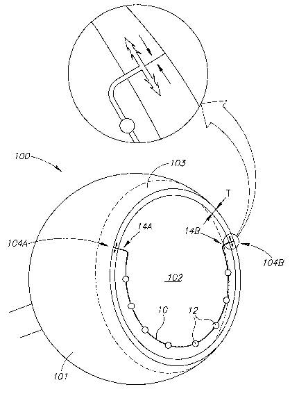
Fig. 3 is a cross section of an eye implanted with Figure l's intraocular
drug dispenser for controlled intraocular drug release purposes.
Detailed Description of Preferred Embodiments of the Present Invention
Figure 1 shows an intraocular drug dispenser 10 including an elongated
support member 11 with a string of discrete drug containing capsules 12, and a

CA 02636068 2008-07-02
WO 2007/083293 PCT/IL2007/000007
-3-
pair of opposite ends 13. T-shaped fixture members 14A and 14B are mounted at
the opposite ends 13 for securely mounting the iiitraocular drug dispenser 10
in
an eye. The T-shaped fixture members 14A and 14B subtend an obtuse angle
a--170 with respect to the support member 11 for assisting in implanting the
intraocular drug dispenser 10 in an eye. Each T-shaped fixture member 14
includes a strut 16 with a pair of oppositely directed self-anchoring
elongated
anchor members 17. The anchor members 17 are formed with leading ends 18
which can be barbed, hooked, and the like, for anchoring into an eye wall. The
drug containing capsules 12 can be enclosed by a soft silicone sheath 19 for
protecting an eye's delicate internal structures on pulling the support member
11
through an eye from one vitrectomy port to another vitrectomy port.
The support member 11 has a total length in the region of 30mm~:5mm
such that the support member 11 can be urged into a horse shoe shape in situ
to
minimize visual disruption on implantation in an eye. The anchor members 17
have a total length L in the range of about 2mm to about 4min, and preferably
3.Oinm 0.10mm, and a diameter D in the range of about 100 m to about 200 m,
and preferably 150 m:~lOgm. The support member 11 and the T-shaped fixture
members 14A and 14B are made fiom a suitable biocompatible material for
implantation in an eye wall, and preferably stainless steel for enabling
slight
resilient deformation for facilitating deploying an intraocular drug dispenser
10 in
a preferred location in an eye's vitreous cavity.
The drug containing capsules 12 have a biocompatible inert coating 21 and
a drug core 22 containing a pharmaceutically active agent which may be in
solid,
gel or liquid form. The coatings 21 are formed from biocompatible materials,
for
example, PMMA, and the like, which are impermeable to the passage of the
pharmaceutically active agent prior to individual rupturing and which can be
ruptured on irradiation with a laser beam causing local heating, local shock
waves, and the like.
Figure 2 shows an intraocular drug dispenser 30 including an elongated
support member 31 with a string of drug containing capsules 32 having

CA 02636068 2008-07-02
WO 2007/083293 PCT/IL2007/000007
-4-
biocompatible inert coatings 33 and drug cores 34 containing a pharmaceutical
active agent. The coatings 33 include a throughgoing small diameter bore 36
stopped by a tliumbtack-like plug 37 with a shaft portion 38 for sealing a
bore 36
and a rounded head 39 formed from suitable biodegradable materials, for
example, a solid polymeric matrix formed from derivatised cellulose and
inethacrylic acid copolymer, and the like. Intraocular drug dispensers 30 are
preferably formed with drug containing capsules 32 having plugs 37 of the same
material but with heads 39 of different thicknesses for governing the time it
takes
them to degenerate from the same start time on implantation in an eye. Thus,
the
plug 37A having the thinnest head is the first plug to degenerate to release
its
capsule's drug contents whilst the plug 37B having the thickest head is the
last
plug to degenerate to release its capsule's drug contents.
Alternatively, the drug containing capsules 32 can be stopped by plugs of
substantially the same dimensions but formed from different materials having
different self-degradation rates for governing their degeneration time from
implantation in an eye.
Figure 3 shows an eye 100 having an eye wall 101, and a vitreous cavity
102. The eye wall 101 includes a circumferential pars plana 103 whose width
increases from a minimum widtli WN of about 3.5mm to a maximum width WT of
about 4.5inm, and which has a largely uniform thickness T of about 1mm. The
implantation of the intraocular drug dispenser 10 in a suitably prepared eye
100 is
as follows:
An eye surgeon threads the intraocular drug dispenser 10 with its soft
silicone sheath 19 intact from a tllroughgoing incision 104A made in the pars
plana 103 to an opposite throughgoing incision 104B. The eye surgeon removes
the soft silicone sheath 19. The eye surgeon inserts the T-shaped fixture
member
14A into opposite facing side surfaces of the throughgoing incision 104A so as
to
draw them together. The eye surgeon bends the support member 11 downwards
from the T-shaped fixture member 14A and inserts the T-shaped fixture member
14B into the opposite facing side surfaces of the throughgoing incision 104B
so

CA 02636068 2008-07-02
WO 2007/083293 PCT/IL2007/000007
-5-
as to draw them together. The support member 11 only marginally disrupts
vision, if at all.
In the case of drug containing capsules 12 intended to be ruptured by laser
radiation, a physician can einploy any standard contact lens for peripheral
retina
inspection for assisting him in directing a laser beam towards a drug
containing
capsule for rupturing same. A physician may rupture two drug containing
capsules 12 simultaneously to double the drug dosage to a particular patient
depending on his clinical condition.
While the invention has been described with respect to a limited number of
embodiments, it will be appreciated that many variations, modifications, and
other applications of the invention can be made within the scope of the
appended
claims.

Representative Drawing
A single figure which represents the drawing illustrating the invention.
Administrative Status

2024-08-01:As part of the Next Generation Patents (NGP) transition, the Canadian Patents Database (CPD) now contains a more detailed Event History, which replicates the Event Log of our new back-office solution.

Please note that "Inactive:" events refers to events no longer in use in our new back-office solution.

For a clearer understanding of the status of the application/patent presented on this page, the site Disclaimer , as well as the definitions for Patent , Event History , Maintenance Fee  and Payment History  should be consulted.

Event History

Description Date
Application Not Reinstated by Deadline 2013-01-04
Time Limit for Reversal Expired 2013-01-04
Deemed Abandoned - Failure to Respond to Maintenance Fee Notice 2012-01-04
Inactive: Abandon-RFE+Late fee unpaid-Correspondence sent 2012-01-04
Appointment of Agent Requirements Determined Compliant 2008-12-04
Inactive: Office letter 2008-12-04
Revocation of Agent Requirements Determined Compliant 2008-12-04
Letter Sent 2008-12-02
Inactive: Cover page published 2008-11-05
Inactive: Notice - National entry - No RFE 2008-11-03
Inactive: First IPC assigned 2008-08-21
Application Received - PCT 2008-08-20
Inactive: Single transfer 2008-07-17
Appointment of Agent Request 2008-07-14
Revocation of Agent Request 2008-07-14
National Entry Requirements Determined Compliant 2008-07-02
Application Published (Open to Public Inspection) 2007-07-26

Abandonment History

Abandonment Date Reason Reinstatement Date
2012-01-04

Maintenance Fee

The last payment was received on 2010-12-10

Note : If the full payment has not been received on or before the date indicated, a further fee may be required which may be one of the following

  • the reinstatement fee;
  • the late payment fee; or
  • additional fee to reverse deemed expiry.

Please refer to the CIPO Patent Fees web page to see all current fee amounts.

Fee History

Fee Type Anniversary Year Due Date Paid Date
MF (application, 2nd anniv.) - standard 02 2009-01-05 2008-07-02
Basic national fee - standard 2008-07-02
Registration of a document 2008-07-17
MF (application, 3rd anniv.) - standard 03 2010-01-04 2009-12-15
MF (application, 4th anniv.) - standard 04 2011-01-04 2010-12-10
Owners on Record

Note: Records showing the ownership history in alphabetical order.

Current Owners on Record
NULENS LTD
Past Owners on Record
JOSHUA BEN NUN
Past Owners that do not appear in the "Owners on Record" listing will appear in other documentation within the application.
Documents

To view selected files, please enter reCAPTCHA code :


To view images, click a link in the Document Description column. To download the documents, select one or more checkboxes in the first column and then click the "Download Selected in PDF format (Zip Archive)" or the "Download Selected as Single PDF" button.

List of published and non-published patent-specific documents on the CPD .

If you have any difficulty accessing content, you can call the Client Service Centre at 1-866-997-1936 or send them an e-mail at CIPO Client Service Centre.


Document
Description 
Date
(yyyy-mm-dd) 
Number of pages   Size of Image (KB) 
Claims 2008-07-02 3 121
Description 2008-07-02 5 241
Representative drawing 2008-07-02 1 13
Abstract 2008-07-02 1 54
Drawings 2008-07-02 2 28
Cover Page 2008-11-05 1 33
Notice of National Entry 2008-11-03 1 208
Courtesy - Certificate of registration (related document(s)) 2008-12-02 1 104
Reminder - Request for Examination 2011-09-07 1 122
Courtesy - Abandonment Letter (Maintenance Fee) 2012-02-29 1 172
Courtesy - Abandonment Letter (Request for Examination) 2012-04-11 1 166
PCT 2008-07-03 6 248
PCT 2008-07-02 8 285
Correspondence 2008-07-14 4 131
Correspondence 2008-11-03 1 85
Correspondence 2008-12-04 1 13
Correspondence 2008-12-02 1 21
Correspondence 2011-09-07 1 23
Correspondence 2012-02-29 1 68
Correspondence 2012-04-11 1 73