Note: Descriptions are shown in the official language in which they were submitted.
CA 02636117 2008-07-02
WO 2007/083078 PCT/GB2006/004879
-1-
TITLE OF THE INVENTION
UNDERWATER EQUIPMENT RECOVERY
BACKGROUND OF THE INVENTION
The invention relates to the recovery of underwater equipment, for example
equipment which has been deployed on the seafloor during surveying.
Equipment can be placed on (or moored to) the seafloor, or towed at depth, for
a variety of reasons. For example, equipment is often deployed underwater
during
sub-sea construction, for oil and mineral exploration, geological exploration,
meteorological and oceanic monitoring and for assisting vessel navigation. A
standard
method for recovering such equipment relies on acoustically activated release
mechanisms.
Figure IA schematically shows a known electromagnetic receiver 2 which is
deployed on the seafloor 4 during an electromagnetic survey and recovered at
the end
of the survey using known techniques (GB 2 382 875 [1]). A similar system is
also
described in US 5,770,945 [2]. The receiver 2 has a main body 6 comprising
antennae
12, instrument housing 14, and floatation device 16. The floatation device 16
comprises a pair of air-filled containers. The main body 6 is connected to a
concrete
ballast weight 8 via releasable connector 10 comprising an acoustic release
mechanism. The receiver 2 is deployed by being dropped overboard from a
support
ship (not shown). The ballast weight 8 is sufficient to overcome the buoyancy
of the
floatation device 16 and the receiver 2 sinks to, and settles on, the seafloor
4. An
electromagnetic survey may then be performed with the receiver 2 collecting
data and
recording it in a memory within the instrument housing 14. In a typical survey
many
such receivers will be distributed over an area of seafloor of interest.
The releasable connector 10 is designed to release in response a remotely
transmitted acoustic signal. Thus, and at the end of a survey, in order to
recover the
recoverable parts of the receiver 2, the support ship broadcasts the
appropriate
acoustic signal causing the releasable connector 10 to release.
CA 02636117 2008-07-02
WO 2007/083078 PCT/GB2006/004879
-2-
Figure 1B schematically shows the receiver of Figure 1 A soon after activation
of the releasable connector 10. On activation of the releasable connector 10,
the main
body 6 is no longer attached to the ballast weight 8. Thus, the main body 6
floats to
the surface under the buoyancy provided the floatation device 16, as
schematically
indicated by arrow 20. Once at the surface of the water, the main body may be
collected by the support ship. The ballast weight 8 remains on the seafloor.
There are a number of disadvantages with this approach.
Firstly, the ballast weight 8 remains on the seafloor. Not only does this
increase the cost of re-deployment (since a new ballast weight is required
each time)
there are ecological implications.
Secondly, acoustic release mechanisms are not completely reliable. This can
leave often very expensive equipment (and data within it) stranded on the
seafloor. In
such cases, the equipment is either written-off as lost (with ecological as
well as
financial implications), or is recovered using an alternative method. One
alternative is
to drag a grappling hook over the general area of loss. However, this is time
consuming and damaging to structures on the seafloor, both natural and man-
made.
Furthermore, in some cases, e.g. in the vicinity of sensitive installations
such as are
often found in a producing oil field, this approach may not be possible at
all. Another
alternative is to use expensive remotely operated sub-sea vehicles, although
these are
often limited by depth and/or lifting capacity, to retrieve stranded
equipment. In
shallow water, divers can be used to attach lines to lost equipment. However,
this is
again expensive and time consuming.
In other examples, in place of a ballast weight, the part of the equipment to
be
recovered may be anchored to a fixed mooring on the seafloor using an
acoustically
releasable connector. Nonetheless, the same considerations as described above
apply.
In some cases, the equipment to be recovered may not have been intended for
seafloor deployment, but may have been accidentally deployed, e.g. because it
was
dropped, or came free of its moorings and did not include a floatation device.
Since
the equipment was not intended for remote seafloor deployment, it is unlikely
to have
been provided with a recovery system of the kind shown in Figures IA and IB
since
these can be expensive and bulky yet of no use in normal operations. Thus
equipment
CA 02636117 2008-07-02
WO 2007/083078 PCT/GB2006/004879
-3-
lost in this way can only be recovered using other means, e.g. by grappling,
or using a
remote sub-sea vehicle and/or divers as described above.
EP 1188662 [3] discloses a floating net into which a powered vehicle may be
driven to allow it to be recovered. However, this scheme only allows for the
recovery
of self-powered vehicles from the surface of a body of water and cannot be
used to
recover equipment deployed underwater.
GB 2279619 [4] discloses an apparatus and method for capturing floating
objects. Again, this cannot be used to recover equipment deployed underwater.
US 6,843,191 [5] discloses a device and methods for raising sunken objects. A
lifting net is guided onto a previously located object by a series of cables
anchored to
the seafloor in its vicinity. Seawater surrounding the object is then frozen
by a
cryogenic freezing unit. When a layer of ice has formed around the object, the
net is
closed around it and the object is lifted to the surface. However, this scheme
is
complex and requires the location of the object to be known in advance.
CA 02636117 2008-07-02
WO 2007/083078 PCT/GB2006/004879
-4-
SUMMARY OF THE INVENTION
According to a first aspect of the invention, there is provided a method for
recovering underwater equipment comprising: attaching an engagement element to
the
equipment prior to its deployment; and, following deployment of the equipment:
lowering a mesh supported by a frame onto the equipment to cause the
engagement
element and the mesh to co-engage; and lifting the frame and the mesh and the
equipment attached thereto upwards to recover the equipment.
The method may provide the primary means for recovering underwater
equipment modules or a fall-back in the event that a conventional recovery
method
fails. Furthermore, the method may be used with equipment which is not
intended for
deployment underwater but which has undergone an accidental deployment, e.g.
because of dropping. This is because cheap and simple engagement elements can
be
attached to any equipment which may be accidentally dropped, e.g. from a
surface
vessel.
Unlike conventional acoustic release systems, the method avoids the need to
leave ballast weights on the seafloor and so can be used as the primary means
of
recovery when it is particularly desired to avoid this. The method is cheaper
and safer
and subject to less stringent water-depth limitations than recovery methods
relying on
divers or remotely operated vehicles. Furthermore, the method inflicts little
or no
damage to existing installations and the bed of the body of water from which
equipment is to be recovered compared with methods based on trawling a
grapple.
The method may be employed to recover equipment from a range of water
depths, for example from a depth of at least 100 in, 200 in, 300 in, 400 in,
500 in,
1000 in, and 2000 in, with or without using positioning transponders.
Specifically, the
method has been successfully tested to recover equipment from a water depth of
1900
in without using positioning transponders. However, there is no real practical
limit to
the depth from which equipment may be recovered using the method. Current
exploration typically extends to water depth of 4000 in, and the method can be
used to
this depth and beyond.
CA 02636117 2008-07-02
WO 2007/083078 PCT/GB2006/004879
-5-
The frame can have a range of suitable areas. The frame area can be as small
as 4 m2, but is more preferably at least 10 m2 or 20 m2. The frame area can be
as large
as 100 m2 or indeed larger still, but is more typically 50 m2 or less. The
frame area can
also be provided in a variety of shapes (as considered in plan view when
deployed),
such as square, rectangular or other polygonal shape, or circular or oval.
The method may be used to recover equipment of any kind. One application of
the method is in the recovery of receivers deployed during surveying, for
example,
electromagnetic receivers deployed during an electromagnetic survey or seismic
receivers deployed during a seismic survey. Surveys such as these often employ
an
array of receivers deployed over a large area on the floor of a body of water.
This
means relatively large numbers of receiver deployments and recoveries are
often
needed for a survey. Furthermore, an individual receiver will typically be
deployed
and recovered many times during its operational lifetime. Thus reliable
recovery of
survey receivers is particularly useful.
The method may further comprise monitoring a load associated with the frame
and mesh to determine whether they are supporting the weight of the equipment.
For
example, an increase in measured load as the frame and mesh are lifted
compared to
the load seen when they were being lowered can be used to indicate that the
equipment has become attached to the mesh through the engagement element and
may
be lifted to the surface. In particular, the static load (i.e. that seen when
there is pause
in the lifting or lowering, or when the frame is being lowered or lifted at a
constant
speed) will be most sensitive to changes in weight associated with the
equipment
becoming attached to the mesh via the engagement element.
For example, a lifting mechanism operable to raise and lower the frame and
the mesh in the water (e.g. a winch and crane aboard a ship) may be provided
with a
load cell configured to measure the tension in a lifting cable attached to the
frame. It
will be generally be simpler to locate the load cell at the winch end of the
lifting cable.
However, if the weight of the lifting cable is significant, it may be
preferable to
position the load cell on the cable nearer to the frame and mesh (or on the
frame
and/or mesh) so that the weight of the cable does not dominate the measured
load.
CA 02636117 2008-07-02
WO 2007/083078 PCT/GB2006/004879
-6-
The frame and mesh may be lowered and raised multiple times at a location to
improve the chance of the engagement element and the mesh co-engaging.
In cases where the location of the equipment is not known precisely, the
method may further comprise searching for the equipment by lowering and
lifting the
frame and mesh at different locations until an increase in load indicates that
the
equipment has become attached to the mesh via the engagement element and is
ready
to be lifted.
To reduce the risk of damage to the equipment during searching, the frame and
mesh may be maintained at a height greater than that of the equipment and
attached
engagement element when they are being moved between locations.
Furthermore, the distance between one location and a subsequent location may
be selected to be less than the width of the frame to help avoid missing areas
of the
bed of water during the search. The frame size can chosen according to the
area to be
searched and areas can be covered more quickly and effectively that with
traditional
grappling methods.
According to a second aspect of the invention, there is provided an apparatus
for recovering equipment from within a body of water, comprising a frame
supporting
a mesh and an engagement element configured to be attached to equipment to be
recovered prior to the equipment's deployment, and shaped to co-engage with
the
mesh in the event that the mesh is lowered onto the engagement element.
The apparatus of the second aspect of the invention may be used to implement
the method of the first aspect of the invention.
The engagement element can take a variety of forms, for example, it may have
an end in the form of an arrow head, or one or more hooks or barbs, for
example.
The mesh may be flexible, e.g., formed of polypropylene rope or steel cabling
so that the frame and mesh easily disassembled and packed in to a smaller area
when
not in use, e.g. when stored on the deck of a ship. Alternatively, the mesh
may be
rigid, for example where particularly heavy loads are expected.
The engagement element may also be provided with a buoyancy device so that
its orientation is maintained when it is submerged regardless of the
orientation of the
equipment to which it is attached. This can help ensure the engagement element
is
CA 02636117 2010-06-18
-7-
appropriately positioned to engage with the mesh when the orientation adopted
by the deployed
equipment on the bed of a body of water is not known in advance. Alternatively
(or in
addition), multiple engagement elements extending in different directions may
be used.
The engagement element and/or the frame or mesh may include a position
transponder.
These can help improve the speed of recovery by providing information on the
absolute or
relative positions of the engagement element and the frame and mesh.
According to a third aspect of the invention there is provided an item if
equipment to which the engagement element of the second aspect of the
invention has been
attached.
In accordance with an aspect of the present invention, there is provided a
method for
recovering underwater equipment from within a body of water comprising:
attaching an
engagement element to the equipment prior to its deployment and, following
deployment of the
equipment: lowering a mesh supported by a frame through the body of water and
onto the
equipment to cause the engagement element and the mesh to co-engage; and
lifting the frame
and the mesh and the equipment attached thereto upwards to recover the
equipment.
In accordance with another aspect of the present invention, there is provided
an apparatus
for recovering equipment from within a body of water, comprising: a frame
supporting a mesh
configured to sink in the body of water when in normal use; and an engagement
element
configured to be attached to the equipment to be recovered prior to the
equipment's deployment
and shaped to co-engage with the mesh in the event that the mesh is lowered
onto the
engagement element.
CA 02636117 2008-07-02
WO 2007/083078 PCT/GB2006/004879
-8-
BRIEF DESCRIPTION OF THE DRAWINGS
For a better understanding of the invention and to show how the same may be
carried into effect reference is now made by way of example to the
accompanying
drawings in which:
Figure 1A schematically shows in section view an electromagnetic receiver to
be recovered from the seafloor according to the prior art;
Figure lB shows the receiver of Figure IA soon after the procedure for
recovering it has been instigated;
Figure 2 schematically shows in section view an item of equipment to be
recovered from the seafloor and an engagement element of an apparatus for
recovering it according to an embodiment of the invention;
Figure 3 schematically shows in perspective view a frame and mesh of an
apparatus according to an embodiment of the invention to be used in
conjunction with
the engagement element shown in Figure 2;
Figure 4 schematically shows a ship seeking to recover equipment according
to an embodiment of the invention;
Figure 5 schematically shows an area of seafloor in which equipment to be
recovered is located;
Figure 6 is similar to Figure 4 but schematically shows the situation when
recovery of the equipment is soon to start;
Figure 7 is similar to Figure 6 but schematically shows the situation when
recovery of the equipment is underway;
Figure 8 shows the engagement element of Figure 2 co-engaging with the
mesh of Figure 3 during recovery of the equipment;
Figures 9A, 9B and 9C schematically show alternative engagement elements
according to embodiments of the invention; and
Figure 10 schematically shows an engagement element including a buoyancy
device in accordance with an embodiment of the invention.
CA 02636117 2008-07-02
WO 2007/083078 PCT/GB2006/004879
-9-
DETAILED DESCRIPTION
Figures 2 and 3 schematically show an apparatus 22, 24 for recovering
equipment deployed underwater according to an embodiment of the invention. In
this
example, the equipment is an equipment module constituting an electromagnetic
receiver 26 lying on the seafloor 4. The receiver is similar to and will be
understood
from the electromagnetic receiver 2 shown in Figure 1. That is to say the
receiver 26
includes a conventional recovery mechanism comprising a floatation device 16,
a
ballast weight 8 and a releasable connector 10 as described above. Thus the
apparatus
22, 24 is for recovering the receiver in the event that the conventional
recovery
mechanism fails. It will be appreciated that in other examples the receiver
(or other
equipment) may not include a conventional recovery mechanism and the apparatus
22,
24 will be the primary means for recovering the equipment. The principle
underlying.
the recovery procedure will be the same in both of these cases.
The apparatus comprises two parts, a first part shown in Figure 2 is an
engagement element 22, referred to in this embodiment as a harpoon. The
harpoon 22
is attached to the receiver using fixings 28. This done before the receiver is
deployed.
Any conventional form of fixing may be employed, e.g. the harpoon 22 may be
welded or bolted to a flange or bracket of the receiver 26. The harpoon 22 is
in a
generally planar form and has an end distal the end fixed to the receiver
which is
formed into the shape of an arrow head. The harpoon 22 (and the fixings 28)
are such
that the weight of the receiver 26 can be supported by the harpoon. In
addition, if
significant dynamic forces are expected during recovery (e.g. due to current
flows and
surface vessel heave), or if the receiver is likely to be deployed in a region
of mud or
silt such that there will be a sucking force as it is lifted away from the
seafloor, the
harpoon 22 and fixings 28 should be designed to be able to accommodate these
additional forces. The harpoon is arranged so that when the receiver is
normally
deployed on the seafloor, the arrow head is pointing upwards and extends to a
height
above neighbouring parts of the receiver 26.
A second part of the apparatus is shown in Figure 3 and comprises a frame 30
supporting a mesh 32 and support cabling 34 (e.g. a chain bridle) attached to
the
CA 02636117 2008-07-02
WO 2007/083078 PCT/GB2006/004879
-10-
frame. The combined frame 30, mesh 32 and support cabling 34 part of the
apparatus
are collectively referred to in this embodiment as a picker 24. The picker 24
can be
raised and lowered in the water column using a lifting mechanism (not shown in
Figure 3) with the frame 30 and mesh 32 remaining substantially horizontal.
The
lifting mechanism will typically comprise a winch and jib/crane arrangement on
a
surface vessel to which the receiver is to be recovered.
The frame 30 in this example is of a generally square shape. It is of a robust
construction, e.g. formed of steel pipe or solid bar section, with lifting
points on the
corners. The frame 30 should be able to bear the weight of the equipment to be
recovered (and any expected additional forces as mentioned above). It will be
advantageous to shape the frame so as to minimize drag as the frame moves in
the
water column as much as possible. The frame may be pre-fabricated or may be
formed
of sections to be assembled when required in order to reduce the storage space
required when not in use.
The mesh 32 in this example comprises netting formed from polypropylene
rope strung between the sides of the frame 30. Other netting materials, such
as high
performance synthetic rope or steel rope, for example, could also be used. The
netting
should be able to bear the weight of the equipment to be recovered (and any
additional
forces likely to be experienced). Although shown taut in Figure 3, there is no
particular need for the mesh to be strung to any particular tightness.
During recovery of equipment, and as explained further below, the harpoon
and the mesh co-engage with one another and thus allow the equipment to be
lifted
from the floor of the body of water. Thus the sizes of the openings in the
mesh and the
size of the engaging part of the harpoon (i.e. the arrow head in this
embodiment) are
chosen so that the engaging part can pass easily through the mesh in the
forward
direction (that is as the picker is lowered down onto the harpoon), but has a
high
chance of becoming snagged on (i.e. co-engaging with) the mesh as the picker
is
subsequently lifted away from the seafloor, thus enabling the receiver to come
away
with it. This can be achieved, for example, if the width of the arrow head
between the
tips of is barbs (i.e. it's greatest extent) broadly corresponds to the
characteristic size
of the openings in the mesh, e.g. if the mesh comprises square openings, the
length of
CA 02636117 2008-07-02
WO 2007/083078 PCT/GB2006/004879
-11-
the side or diagonal of the openings. In a typical application the arrow head
and mesh
openings will have a characteristic size of around 50 cm or so, for example.
Larger
scales, e.g. 1 or 2 meters, or even larger still, may be appropriate for
recovering larger
or particularly heavy equipment. Similarly, smaller scales may be appropriate
in other
circumstances.
The typical overall size of the frame 30 will also depend on the application
at
hand. For recovering receivers used in a typical electromagnetic survey, the
frame
might have side length of, for example, 5 meters or so. However, bigger or
smaller
frames can be used. In general, as will be seen further below, larger frames
will allow
quicker recovery of equipment, especially if their exact location is not
known. Smaller
frames, on the other hand, will be easier to store, handle and deploy
overboard for use.
Thus a large vessel seeking equipment that could be located anywhere within a
large
area would preferably employ a larger frame, for example 10 meters on a side
or
larger. Whereas a smaller frame, for example 2 meters or so on a side, may be
appropriate for small vessel seeking to recover equipment whose location is
known
more precisely. The accuracy with which the picker can be directed toward the
seafloor, which is likely to depend on water depth, will also play a role in
determining
the most appropriate size. For example, in cases where it is difficult to
position the
picker, e.g. because of strong currents or in deep water, a larger frame may
be
preferable.
Figure 4 schematically shows a ship 40 seeking to recover an electromagnetic
receiver 26 using the apparatus (harpoon 22 and picker 24) shown in Figures 2
and 3
according to an embodiment of the invention. The ship floats on the surface of
the
body of water 52 in which the receiver 26 has been deployed. The ship 40 may
be the
vessel supporting the electromagnetic survey, or may be a specialist recovery
ship, for
example in the case that the apparatus 22, 24 does not provide the primary
means of
recovery and so is not normally carried on the vessel performing the survey.
In this example it is assumed that the position of the receiver 26 on the
seafloor 4 (schematically indicated by arrow P in Figure 4) is not known. Thus
the
ship 40 must search for the receiver 26 before it is able to effect recovery.
To seek and
recover the receiver 26, the ship is positioned at a start position
representing a best
CA 02636117 2008-07-02
WO 2007/083078 PCT/GB2006/004879
-12-
first guess, or a random guess if there is no preferred staring point,
(schematically
indicated by arrow Q) and the picker 24 is lowered over the side of the vessel
using
onboard lifting mechanism 42. The lifting mechanism comprises a crane jib 44
and a
winch 46 coupled to a lifting cable 48. The lifting mechanism further includes
a
conventional load sensitive cell (not shown) operable to provide an indication
of the
load applied to the lifting mechanism (i.e. the tension in the lifting cable).
Lifting
mechanisms of this kind are commonly found on ships, especially those used for
surveying, and it is likely that any pre-existing lifting mechanism on the
ship can be
employed with embodiments of the invention. The scale of the lifting mechanism
42,
i.e. its load capability, the length of the lifting cable and geometry of the
jib 44 which
will be appropriate for a given implementation of the invention will depend on
the
size of the frame, the size and weight of the equipment to be recovered and
depth of
water, for example. The support cabling 34 is attached to the lifting cable 48
using
cable coupling 50 so that the picker 24 can be raised and lowered in the water
column
using the lifting mechanism according to conventional techniques. Although a
separate lifting cable 48 and support cabling 34 are shown, it will be
appreciated that a
unitary cable could equally be used.
Once the picker 24 has been deployed overboard, the lifting mechanism 42 is
driven to lower the picker towards the seafloor, as schematically indicated in
Figure 4
by arrow D. As the picker reaches greater depths, the load cell would indicate
an
increasing load L associated with the weight of the picker 24 in water plus a
uniformly
increasing component associated with the increasing weight of the lifting
cable as it is
played out (assuming the picker is not in free fall). The most useful load to
monitor
will be the static load, i.e. that seen when the frame is being lowered or
lifted at a
constant speed or if there is a pause in the lifting or lowering. However, the
non-static
load, i.e. that seen when there is some acceleration of the picker, may also
be used if
appropriate account is taken of the acceleration.
A sudden drop in the indicated load occurs when the frame 30 reaches the
seafloor and its weight is no longer being supported by the lifting mechanism.
The
load just prior to this corresponds to the weight of the picker and the weight
of the
length of lifting cable corresponding to the depth of the water (again
assuming the
CA 02636117 2008-07-02
WO 2007/083078 PCT/GB2006/004879
-13-
picker is not in free fall). The speed at which the picker is lowered through
the water
52 will depend on the rate at which the winch 46 of the lifting mechanism 42
is able
to play out the lifting cable 48 and any considerations associated with
damaging
equipment on the seafloor, or the seafloor itself. For example, in the
vicinity of
sensitive installations the descent rate may be slowed to minimise the risk of
damage
caused by the picker 24 dropping on to the seafloor. Having the picker
approach the
seafloor slowly (at least as it gets closer) will also help prevent damage to
the
equipment to be recovered in the event that the frame 30 of the picker
collides with it.
Once it is determined that the picker 24 is on the seafloor, the playing out
of
lifting cable by the lifting mechanism is stopped and the lifting mechanism is
driven
to lift the picker to a height such that the mesh 32 (taking account of any
slack in it)
would be further from the seafloor than the top of the engagement element 22
(harpoon) attached to the equipment to be recovered, indicated by'height h in
Figure 4.
If the static load on the lifting mechanism is indicated as being the same
when
it is lifted away from the seafloor as it was (at the corresponding height)
when it was
being lowered to the seafloor, this indicated that the picker has not "picked
up"
anything, and so the equipment to be recovered has been missed. (Differences
in non-
static load could also be compared with appropriate account been taken of the
effect
of the difference in acceleration of the picker between being lowered and
lifted.)
Thus the ship moves to another location and tries again. The ship could be
moved randomly between locations, but in general it will be more efficient to
follow a
systematic search plan.
Figure 5 schematically shows a plan view of the area of seafloor 4 shown in
Figure 4. The picker 24 is at position Q and the receiver 26 to be recovered
is shown
at position P. Dashed lines are used in Figure 5 to indicate search grid
defining a
series of search squares. A search square is searched by positioning the
picker 24 over
that square and lowering it to, and lifting it from, the seafloor as described
above in
connection with Figure 4. Once a square is searched without success (i.e. the
picker
has been lowered to and lifted from the seafloor with no appreciable change in
measured load), the picker is moved to another square. Thus the area is
searched
square by square. The order in which the squares are searched can be according
to any
CA 02636117 2008-07-02
WO 2007/083078 PCT/GB2006/004879
-14-
known search technique. For example, a increasing spiral around the start
square
(containing Q) may be employed. However, it may also be appropriate to take
account
of the manoeuvreability of the ship and possible differences in the degree of
uncertainty in different directions. For example, it may be more appropriate
to
perform a raster search in strips rather than a spiral search.
The size of the search squares will depend on the size of the frame 30 and the
accuracy with which it can be positioned on the seafloor. For example, if the
frame
can be very accurately positioned, search squares which are only just smaller
than the
frame size may be appropriate. However, in other cases smaller search squares
will be
appropriate, for example squares having a characteristic dimension which is
half-that
of the frame. This can help to ensure areas of seafloor are not missed between
neighbouring raise and lower operation. In this case it will be assumed that
the search
is to be a spiral search and the search squares are only slightly smaller than
the frame
size, e.g. 90% of it.
At the end of the procedure described above in relation to Figure 4 for
searching the search square containing point Q, the picker is located at a
height above
the seafloor which is greater than the height h of the harpoon 22. While
maintaining
this height the ship 40 repositions the picker over the next search square,
this square is
identified in Figure 5 as square S1. By maintaining the picker at a height
greater than
the height of the harpoon, the risk of the picker 24 banging into the
equipment to be
recovered as the picker is repositioned is reduced. Where the seafloor terrain
is rough,
or where other equipment is located on the seafloor, it may be preferable to
lift the
picker 24 higher still as it is moved between search squares. However, in
general it
will be desirable to keep lift the picker as little as possible during
searching to
increase search speed.
Once the picker is positioned above search square Si, it is lowered to, and
lifted from, the seafloor 4 as described above. The load on the lifting
mechanism as
the picker is lifted away from the seafloor will again indicate that it has
not "picked
up" anything, Thus the ship repositions the picker above search square S2 and
the
search continues, and so on through search squares S3 to s10 as indicated in
Figure 5.
CA 02636117 2008-07-02
WO 2007/083078 PCT/GB2006/004879
-15-
Eventually, following the above described search algorithm, the picker 24 will
be positioned above the search square containing the equipment 26 to be
recovered,
i.e. search square S 11 containing point P.
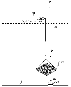
Figure 6 is similar to and will be understood from Figure 4. However, in
Figure 6, the search has progressed to search square s11, such that the picker
is now
above the receiver 26 and in the process of being lowered towards it, as
indicated by
the arrow D. As the picker approaches the seafloor it lands over the receiver
26. If the
mesh 34 is slack, the frame 32 may settle on the seafloor 4 around the
receiver with
the mesh draped over it. If, on the other hand, the mesh is not sufficiently
slack, the
frame may be supported to some extent (via the mesh) by the receiver. If the
equipment to be recovered is considered delicate, a slack mesh may be
preferred to
reduce the chance of the equipment having to support the weight of the frame
if this is
a concern.
In either case, as the picker settles over the receiver, the harpoon 22 passes
through the opening in the mesh 32. When the weight of the picker is relieved
from
the lifting cable, the reduction in load on the lifting mechanism is indicated
by the
load cell, and the lifting mechanism stops playing out the lifting cable and
starts to lift
the picker away from the seafloor as described above. However, as this happens
the
arrowhead on the harpoon 22 snags on (i.e. co-engages with) the netting
comprising
the mesh 32. Thus as the picker 24, is lifted away from the seafloor 4, the
receiver is
co-engaged with it and is also lifted. As the picker and receiver clear the
seafloor, the
load cell indicates that the load on the lifting mechanism is greater than it
was as it
was being lowered due to the extra weight of the receiver. Thus the operator
on the
ship or (or an appropriately configured controller if the equipment recovery
process is
automated) knows that the harpoon 22 has engaged with the mesh 32 and so the
search algorithm can stop and the picker can be lifted to the water surface
bringing the
receiver 22 with it.
Figure 8 is similar to and will be understood from Figure 7. However, Figure 8
shows the situation after the harpoon 22 and the mesh 32 have become co-
engaged,
and with the picker 24 and attached receiver 26 being lifted towards the water
surface,
as indicated by the arrow U.
CA 02636117 2008-07-02
WO 2007/083078 PCT/GB2006/004879
-16-
Figure 7 schematically shows the co-engagement of the harpoon 22 with the
mesh 32 during recovery of the receiver 22 from the body of water 52. Figure 7
shows
the receiver after it has been lifted free of the water surface and is ready
to be moved
to the deck of the ship to complete the recovery process. The receiver 26 may
be
deposited on the deck of the ship by appropriate manoeuvring of the picker, or
may be
separately retrieved from the picker while it is held at the water surface,
e.g. using a
separate launch.
It will be understood that while recovery of a receiver intended for seafloor
deployment and having a conventional primary recovery mechanism (i.e. remotely
detachable ballast weight) which has failed has been described above, in other
cases a
recovery mechanism according to embodiments of the invention will be the
primary
means of recovery for equipment intended for seafloor deployment. Furthermore,
because a suitable engagement element can easily and cheaply be attached to
any
equipment intended for underwater use, whether or not it is intended to be
released
onto the seafloor, it can be beneficial to provide the equipment with an
engagement
element so that it can be recovered as described above in the event it is
accidentally
dropped or otherwise becomes stranded onto the seafloor.
It some embodiments, the engaging element may be provide with a
conventional positioning transponder (e.g. an acoustic transponder) to assist
in
locating the equipment to be recovered using suitable tracking instruments on
the ship
and so reduce search time. This can be particularly helpful where the
engagement
element is to be attached to an item of equipment not normally intended for
seafloor
deployment as a means of insurance against accidental loss since such
equipment is
unlikely to have its own positioning transponder.
Furthermore, the picker may also be provided with a positioning transponder
to allow its position to be determined. This can help in ensuring the search
is effected
as efficiently as possible. For example, if both the engagement element (or
the
equipment to which it is attached) and the picker are provided with a
positioning
transponder, the positions of each (and hence their positions relative to one
another)
can be determined so that the picker can be guided towards the equipment to be
recovered based on their measured positions.
CA 02636117 2008-07-02
WO 2007/083078 PCT/GB2006/004879
-17-
Information regarding the height of the frame above the seafloor, e.g. from a
conventional echo sounder or other depth transducer, may also be provided to
allow
the picker to be dropped through the seawater as quickly as possible, but
slowed down
as it approaches the bottom to reduce the chance of damage.
Figures 9A to 9C schematically show alternative designs for the engaging end
of an engagement element and a portion of a mesh according to other
embodiments of
the invention.
In Figure 9A, the engagement element 92 comprises a central support 94 to be
attached to equipment prior to its deployment at one end (not shown) and a
pair of
barb elements pivotably attached to an upper end of the central support. An
upper
shroud 97 fixed to the central support prevents the barbs from extending
beyond a
limit angle from the central support, for example beyond 45 degrees or so. A
pair of
springs 98 urge the barbs 96 open to this limit. The springs are schematically
shown in
Figure 9A as helical springs connecting between the central support and the
respective
bards. However, in practice the springs would be arranged to leave the region
under
the barbs clear. For example pivot mounted springs may be used. The advantage
of
this arrangement is that the engagement element can deform when passing
through the
openings in the mesh and so a rigid mesh could be used. This may be
advantageous
when heavy loads are to be recovered.
In Figures 9B and 9C, the arrowhead design described above is replaced with a
single hook design (Figure 9B) and a single barb design (Figure 9C). It will
be
appreciated that many other designs could be used, for example the engagement
element is not constrained to a generally planar form and designs based on
barbs,
hooks, hitches etc extending in several directions could be used which allow
the
engagement element to pass easily through a mesh lowered onto it, but to snag
on the
mesh as it is lifted upwards. In general, the most appropriate design for the
engagement element may also depend on characteristics of the equipment to be
recovered. For example, its mass in water, mass in air, shape and balance,
sensitivity
to extra appendages and so on.
Figure 10 schematically shows an engagement element which may be used in
cases where it cannot be predicted which orientation the equipment to be
recovered
CA 02636117 2008-07-02
WO 2007/083078 PCT/GB2006/004879
-18-
will adopt on the seafloor. In this example it is assumed that the equipment
is a cuboid
box 110 that has been accidentally dropped on to the seafloor 4. The
engagement
element 112 comprises an arrow head 114, a shaft 116 and a buoyancy device 122
and
a flexible coupling 118, (e.g. rope or chain). The flexible coupling 118 is
attached to
the equipment 110 in advance of the time it is accidentally lost (i.e. it may
be attached
before the equipment 110 enters the water, or at a later stage, e.g. when it
is already
underwater, but is about to be moved and so there is a risk of dropping it).
When the
equipment 110 is dropped to the seafloor, the flexible coupling and buoyancy
device
ensure that the arrow head part of the engagement element remains pointing
upwards.
This it may be recovered as described above by lowering a mesh onto it. The
buoyancy device 122 may be, for example, one or more air filled chambers a
volumes
of polystyrene or other buoyant material. Because the engagement element 112
is not
rigidly mounted, there is an increased chance that it will not pass through
the mesh but
will be simply pressed down by it. In cases such as this where it is
considered that
there is a reasonable chance of the harpoon and mesh not engaging with each
other,
multiple several lifts and drops in each search square may be executed to help
avoid
missing the equipment.
In deep water, the combined weight of the picker and the length of lifting
cable
required to reach the seafloor may mean it is difficult to reliably sense the
additional
weight of the equipment (e.g. because underwater currents or surface heave
cause
variations in load which are significantly greater than the weight of the
equipment). In
cases such as this, it may be beneficial to locate the load cell not on the
surface vessel,
but closer to the picker (with an appropriate communications link to the
surface) so
that the weight of cable above the load cell does not effect the measurement.
Likewise, in cases where particular sensitivity is required, it may be
beneficial to
locate the load cell within the mesh itself. By providing a strain gauge (or
multiple
strain gauges) within the webbing comprising the mesh, a significant change in
measured load can be apparent even for relatively light equipment, so long as
the
equipment has a measureable weight compared to the weight of the mesh
supported
through the strain gauge (or other form of load cell).
CA 02636117 2008-07-02
WO 2007/083078 PCT/GB2006/004879
-19-
Thus there has been described an apparatus and method for recovering
equipment from within a body of water. The apparatus comprises a frame
supporting a
mesh and an engagement element. The engagement element is shaped to co-engage
with the mesh and is attached to the equipment to be recovered prior to its
deployment. Following deployment of the equipment, its recovery can be
effected by
lowering the mesh supported by the frame onto the equipment to cause the
engagement element and the mesh to co-engage. The frame and mesh may then be
lifted to the surface of the water, bringing the equipment with them. Recovery
may
include searching for the equipment by monitoring a load associated with the
frame
and the mesh as it is lowered and raised at different locations, whereby an
appropriate
increase in load is taken to indicate that the equipment has become attached
to the
mesh. Thus embodiments of the invention provide a simple, cheap and reliable
apparatus and method for recovering underwater equipment. Embodiments of the
invention provide benefits such as:
= The apparatus is simple and easy to operate, it requires no special
materials
or tolerances and inflicts minimum damage to the seafloor
= Any sub-sea equipment can be fitted with an engagement element with ease
and at low cost which ensures its recovery using a mesh supported on a frame
at any
time in the future for a fraction of the cost of traditional recovery methods
(diver/ROV).
= The frame size can be varied according to the area to be searched and there
is
no limitation on water depth, as there would be using remotely operated
vehicles or
divers.
= Because of the frame size large areas can be covered far more quickly and
effectively that traditional grappling methods.
= In areas of environmental sensitivity, instruments/moorings can be recovered
leaving nothing on the seafloor, in contrast to standard acoustic
deployment/recovery
methods, which leave a bottom weight on the seafloor after recovery.
Thus the apparatus may be used to easily recover instruments or other
equipment that have been placed or moored on the seafloor in a variety of
water
depths, on purpose or accidentally, without the need for acoustically
activated release
CA 02636117 2008-07-02
WO 2007/083078 PCT/GB2006/004879
-20-
mechanisms. The device is economical to construct and requires deployment
equipment that is fitted as standard to most vessels involved in sub-sea
projects. The
device is easily dismantled and takes up minimal space whilst not in use, If
required it
can be constructed locally to the project as no specialized materials or
tolerances are
required. Almost any item that may be placed on the seafloor, towed at depth,
moored
or accidentally lost, regardless of size, shape or water depth can be
recovered using
the apparatus significantly more easily and cheaply than with currently
available
methods.
CA 02636117 2008-07-02
WO 2007/083078 PCT/GB2006/004879
-21-
REFERENCES
[1] GB 2382875 Al (University of Southampton)
[2] US 5,770,945 (Constable)
[3] EP 1188662 (Pfitzner)
[4] GB 2279319 (Bolton)
[5] US 6,843,191 (Makotinsky)