Language selection

Search

Patent 2636403 Summary

Third-party information liability

Some of the information on this Web page has been provided by external sources. The Government of Canada is not responsible for the accuracy, reliability or currency of the information supplied by external sources. Users wishing to rely upon this information should consult directly with the source of the information. Content provided by external sources is not subject to official languages, privacy and accessibility requirements.

Claims and Abstract availability

Any discrepancies in the text and image of the Claims and Abstract are due to differing posting times. Text of the Claims and Abstract are posted:

  • At the time the application is open to public inspection;
  • At the time of issue of the patent (grant).
(12) Patent Application: (11) CA 2636403
(54) English Title: CUTTING PLATE SECURED BY INTERLOCK ON A SUPPORT PLATE
(54) French Title: PLAQUE DE COUPE FIXEE EN CORRESPONDANCE GEOMETRIQUE SUR UNE PLAQUE D'APPUI
Status: Deemed Abandoned and Beyond the Period of Reinstatement - Pending Response to Notice of Disregarded Communication
Bibliographic Data
(51) International Patent Classification (IPC):
  • B23B 27/16 (2006.01)
(72) Inventors :
  • KABELITZ, JOERG (Germany)
  • SCHUMACHER, HANS-PETER (Germany)
  • KVITTA, MANFRED (Germany)
  • KVITTA, RALPH (Germany)
  • EDER, OTTO (Germany)
(73) Owners :
  • CERAMTEC AG INNOVATIVE CERAMIC ENGINEERING
(71) Applicants :
  • CERAMTEC AG INNOVATIVE CERAMIC ENGINEERING (Germany)
(74) Agent: ROBIC AGENCE PI S.E.C./ROBIC IP AGENCY LP
(74) Associate agent:
(45) Issued:
(86) PCT Filing Date: 2007-01-05
(87) Open to Public Inspection: 2007-07-19
Availability of licence: N/A
Dedicated to the Public: N/A
(25) Language of filing: English

Patent Cooperation Treaty (PCT): Yes
(86) PCT Filing Number: PCT/EP2007/050110
(87) International Publication Number: WO 2007080151
(85) National Entry: 2008-07-07

(30) Application Priority Data:
Application No. Country/Territory Date
10 2006 001 309.3 (Germany) 2006-01-09
10 2006 052 701.1 (Germany) 2006-11-07

Abstracts

English Abstract


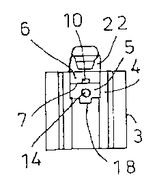
The invention relates to a cutting tool for machining processes, in essence
composed of a clamping holder (3) with a recess (4) for accepting a support
plate (5) and with a cutting plate (6) secured on the support plate (5) by way
of a clamping claw (22). It is proposed, for secure fastening of the cutting
plate (6) on the clamping holder (3), that an interlocking tongue-and-groove
connection is used for positioning of the cutting plate (6) on the support
plate (5).


French Abstract

L'invention concerne un outil de coupe pour l'usinage avec enlèvement de matière, essentiellement constitué d'un support de serrage (3) doté d'une découpe (4) de réception d'une plaque d'appui (5) et d'une plaque de coupe (6) fixée sur la plaque d'appui (5) par une griffe de serrage (22). Pour fixer de manière sûre la plaque de coupe (6) sur le support de serrage (3), l'invention propose que la plaque de coupe (6) soit placée sur la plaque d'appui (5) par l'intermédiaire d'une liaison en correspondance géométrique à rainure et ressort.

Claims

Note: Claims are shown in the official language in which they were submitted.


Claims
1. A cutting tool for machining processes, consisting
essentially of a clamping holder (3) with a recess (4)
for receiving a support plate (5), and with a cutting
plate (6) which is secured to the support plate (5) by
means of a clamping claw (22), characterised in that
the cutting plate (6) is positioned on the support
plate by means of an interlocking tongue-and-groove
connection.
2. A cutting tool according to Claim 1, characterised in
that the cutting plate (6) has on its underside (7)
oriented towards the support plate (5) a groove (10) in
which a feather key (9) engages in a form-fitting
manner, which feather key (9) is either formed
integrally with the support plate (5) or is fastened
therein or thereon.
3. A cutting tool according to Claim 2, characterised in
that the upper side (8) of the support plate (5)
oriented towards the cutting plate (6) has a slot (11)
into which the feather key (9) is inserted in a form-
fitting manner as a separate component.
4. A cutting tool according to Claim 2 or 3, characterised
in that the feather key (9) is made of a ceramic
material.
5. A cutting tool according to any one of Claims 1 to 4,
characterised in that the cutting plate (6) has on its
underside (7) oriented towards the support plate (5) a
raised feather key (5) which engages in a form-fitting
manner in a corresponding groove (11) in the upper
side (8) of the support plate (5) oriented towards the
cutting plate (6).
6. A cutting tool according to any one of Claims 1 to 5,
characterised in that the support plate (5) is secured

6
to the clamping holder by means of a screw (14), the
support plate (5) being pulled into its seating in the
recess by tightening of the screw (14).
7. A cutting tool according to any one of Claims 1 to 6,
characterised in that the support plate (5) has on its
underside (16) oriented towards the clamping holder (3)
a tongue (17) which engages in a corresponding
groove (18) in the clamping holder (3) or vice versa.
8. A cutting plate for machining processes, with an upper
side (19) having a cutting edge and an underside (7)
for being supported on a cutting tool, in particular
for use in a cutting tool according to any one of
Claims 1 to 7, characterised in that the underside (7)
of the cutting plate (6) has a groove (10) for
fastening the cutting plate (6) to the support by means
of an interlocking tongue-and-groove connection.
9. A cutting plate according to Claim 8, characterised in
that the groove (10) on the underside (7) is formed
continuously.
10. A cutting plate according to Claim 8 or 9,
characterised in that the material of the cutting
plate (6) is a ceramic material or a cubic boron
nitride.

Description

Note: Descriptions are shown in the official language in which they were submitted.


CA 02636403 2008-07-07
Cutting plate secured by interlock on a support plate
The invention relates to a cutting tool for machining
processes according to the preamble of Claim 1, and to a
cutting plate for securing to the cutting tool.
Figs. 1 a, b, c show a support plate according to the prior
art, in this case for receiving circular cutting plates.
For this purpose the support plate 1 is provided with a 120
degree prism 2 in which a cutting plate (not shown here) is
inserted (cf. EP 0 350 938 A1).
With a cutting plate thickness of, for example, 4.76 mm,
the cutting plate is very thin at the throat of the prism.
In addition the tolerances of the cutting plate with
respect to the support plate lead to inexact positioning.
An adequate seating of the plate is therefore not ensured.
At present this applies in particular to CBN cutting
plates, that is, cutting plates made of cubic boron
nitride.
It is the object of the invention to specify a cutting tool
according to the preamble of Claim 1, and an associated
cutting plate in which the fastening of the cutting plate
to the cutting tool is substantially improved.
According to the invention this object is achieved by the
features of Claims 1 and 8.
Because the cutting plate is positioned on the support
plate by means of an interlocking tongue-and-groove
connection, fastening is substantially improved.
In a configuration according to the invention the cutting
plate has on its underside oriented towards the support
plate a groove in which a feather key engages form-
fittingly, which feather key is either formed integrally
with the support plate or is fastened therein or thereon.

CA 02636403 2008-07-07
WO 2007/080151 PCT/EP 2007/050110
2
The upper side of the support plate oriented towards the
cutting plate advantageously has a slot into which the
feather key is inserted form-fittingly as a separate
component.
The feather key is preferably made of a ceramic material.
In one configuration, the cutting plate has on its
underside oriented towards the support plate a raised
feather key which engages form-fittingly in a corresponding
groove in the upper side of the support plate oriented
towards the cutting plate.
The support plate is advantageously fastened to the
clamping holder, as far as possible, by means of a screw,
the support plate being pulled into its seating in the
recess by tightening of the screw.
In a configuration, the support plate has on its underside
oriented towards the clamping holder a tongue which engages
in a corresponding groove in the clamping holder, or vice
versa.
A cutting plate according to the invention for machining
processes, with an upper side having a cutting edge and an
underside for being supported on a cutting tool, in
particular for use in the cutting tool described above, is
characterised according to the invention in that the
underside of the cutting plate has a groove for fastening
of the cutting plate to the support by means of an
interlocking tongue-and-groove connection.
The groove on the underside is advantageously formed
continuously. The material of the cutting plate consists
preferably of a ceramic. It may also be a cubic boron
nitride (CBN) or a metal.
Through the interposition according to the invention of an
interlocking tongue-and-groove connection between cutting

CA 02636403 2008-07-07
WO 2007/080151 PCT/EP 2007/050110
3
plate and support plate, improved seating of the plate is
ensured because of the flat-ground cutting plate and the
guidance in the key. A further advantage lies in the fact
that the support plate can be screwed from the front and
the groove wedge can also be designed in a ceramic
material, which results in less warping in the holder
through the heat generated during machining.
The invention is described in more detail below with
reference to the Figures.
Figs. 2 a, b, c show a clamping holder 3 with a recess 4
for receiving a support plate 5. The support plate 5 is
itself shown in Figs. 3 a, b, c, d. Figs. 4 a, b, c show
the associated feather key 9 and Fig. 5 shows a cutting
plate 6 according to the invention.
The cuttina plate 6 is preferarlv a circular cutt;ng plate
but may also have other geometries; it has a groove 10 in
its underside 7 oriented towards the support plate 5 (cf.
in particular Fig. 5). The cutting plate 6 is preferably
made of a ceramic material, but may also consist of another
material, for example metal. The cutting plate 6 is
fastened to the clamping holder 3 by means of a clamping
claw 22.
A support plate 5, shown in detai 1 in Fig. 3, is inserted
in a recess 4 of the clamping holder 3. The support
plate 5 has on its upper side 8 oriented towards the
cu ttinq plate 6 a feather key 9, the width 9a of which is
ad arted to the groove 10 in the cutting plate 6.
The feather key 9 is preferably a separate component (cf.
Fi g.4) and is made of a ceramic material.
In this preferred embodiment a slot 11, into which the
feather key 9 is inserted, is formed in the upper side 8 of
th e support plate 5.

CA 02636403 2008-07-07
WO 2007/080151 PCT/EP 2007/050110
4
The support plate 5 is screwed to the clamping holder 3.
For this purpose it has a bore 12 with a conically
decreasing diameter 13. A screw 14 can be inserted in this
bore 12, the head of which screw 14 bears against the
conically decreasing diameter 13 and the thread of which
screw 14 engages in a corresponding screw thread in the
clamping holder 3. The support plate 5 is pulled into its
seating in the recess 4 of the clamping holder 3 by
tightening of the screw 14.
On its underside 16 oriented towards the clamping holder 3
the support plate 5 has a tongue 17 which engages in a
corresponding groove 18 in the clamping holder 3. This
groove 18 (cf. Fig. 2 c) serves to guide the support
plate 5 on the clamping holder 3.
The support [sic] plate 6 (cf. Fig. 5) is configured here
as a circular cutting plate and is provided with a flat
upper side 19. The groove 10 in its underside 7 is
preferably formed continuously. A cubic boron nitride
(CBN) is preferably suitable as the material for this
cutting plate 6. However, it may consist of a different
material. The flank 20 of the cutting plate 6 preferably
has a conical configuration, the diameter of the cutting
plate 6 decreasing in the direction towards the groove 10.
The feather key 9 (cf. Fig. 4) is provided with a
chamfer 21 on each of its edges and preferably consists of
a ceramic material.

Representative Drawing
A single figure which represents the drawing illustrating the invention.
Administrative Status

2024-08-01:As part of the Next Generation Patents (NGP) transition, the Canadian Patents Database (CPD) now contains a more detailed Event History, which replicates the Event Log of our new back-office solution.

Please note that "Inactive:" events refers to events no longer in use in our new back-office solution.

For a clearer understanding of the status of the application/patent presented on this page, the site Disclaimer , as well as the definitions for Patent , Event History , Maintenance Fee  and Payment History  should be consulted.

Event History

Description Date
Letter Sent 2018-06-26
Application Not Reinstated by Deadline 2012-01-05
Time Limit for Reversal Expired 2012-01-05
Deemed Abandoned - Failure to Respond to Maintenance Fee Notice 2011-01-05
Letter Sent 2009-05-26
Inactive: Office letter 2009-05-26
Inactive: Single transfer 2009-04-02
Inactive: Declaration of entitlement - PCT 2009-02-11
Inactive: Cover page published 2008-10-29
Inactive: Notice - National entry - No RFE 2008-10-18
Inactive: First IPC assigned 2008-08-26
Application Received - PCT 2008-08-25
National Entry Requirements Determined Compliant 2008-07-07
Application Published (Open to Public Inspection) 2007-07-19

Abandonment History

Abandonment Date Reason Reinstatement Date
2011-01-05

Maintenance Fee

The last payment was received on 2009-11-23

Note : If the full payment has not been received on or before the date indicated, a further fee may be required which may be one of the following

  • the reinstatement fee;
  • the late payment fee; or
  • additional fee to reverse deemed expiry.

Patent fees are adjusted on the 1st of January every year. The amounts above are the current amounts if received by December 31 of the current year.
Please refer to the CIPO Patent Fees web page to see all current fee amounts.

Fee History

Fee Type Anniversary Year Due Date Paid Date
Basic national fee - standard 2008-07-07
MF (application, 2nd anniv.) - standard 02 2009-01-05 2008-11-13
Registration of a document 2009-04-02
MF (application, 3rd anniv.) - standard 03 2010-01-05 2009-11-23
Registration of a document 2018-03-28
Owners on Record

Note: Records showing the ownership history in alphabetical order.

Current Owners on Record
CERAMTEC AG INNOVATIVE CERAMIC ENGINEERING
Past Owners on Record
HANS-PETER SCHUMACHER
JOERG KABELITZ
MANFRED KVITTA
OTTO EDER
RALPH KVITTA
Past Owners that do not appear in the "Owners on Record" listing will appear in other documentation within the application.
Documents

To view selected files, please enter reCAPTCHA code :


To view images, click a link in the Document Description column. To download the documents, select one or more checkboxes in the first column and then click the "Download Selected in PDF format (Zip Archive)" or the "Download Selected as Single PDF" button.

List of published and non-published patent-specific documents on the CPD .

If you have any difficulty accessing content, you can call the Client Service Centre at 1-866-997-1936 or send them an e-mail at CIPO Client Service Centre.


Document
Description 
Date
(yyyy-mm-dd) 
Number of pages   Size of Image (KB) 
Abstract 2008-07-06 1 75
Description 2008-07-06 4 154
Claims 2008-07-06 2 67
Drawings 2008-07-06 5 43
Representative drawing 2008-10-28 1 4
Reminder of maintenance fee due 2008-10-19 1 111
Notice of National Entry 2008-10-17 1 193
Courtesy - Certificate of registration (related document(s)) 2009-05-25 1 102
Courtesy - Abandonment Letter (Maintenance Fee) 2011-03-01 1 173
Reminder - Request for Examination 2011-09-06 1 122
PCT 2008-07-06 8 243
PCT 2008-09-07 1 45
Fees 2008-11-12 1 54
Correspondence 2009-02-10 2 74
Correspondence 2009-05-25 1 17
Fees 2009-11-22 1 54