Note: Descriptions are shown in the official language in which they were submitted.
CA 02636510 2008-07-11
WO 2007/079544 PCT/AU2007/000028
~
REFUSE CHUTE
FIELD OF THE IN1fI-;N'TIOIrI
The present invention relates to a refuse chute for gravity disposal of
refuse from storeys of a multi-storey building such as during building
construction
or refurbishment.
BACkCGf~OUiVII OF TliE INVENTION
It is normal practice on muiti-storey building sites to provide for the
removal
of refuse from upper floors of a building by a refuse chute which defines a
shaft
whereby all types of building refuse may be dropped from the upper floors down
the chute shaft to a container located at the bottom of the chute, eg at
ground
level.
Such chutes are u$ually assombied from individual tubular sections of
circular or quadrilateral cross-section which are stackable to provide a
height
suitable to the specific building. The individual.sections which, when in
place,
extend vertically along the building have one or more refuse inlet structures
that
enable a user to put refuse into the chute for gravity disposal. As such,
conventional refuse chutes have many adjustable components to fit different
floor
heights in buildings, resulting in many pieces to be assembled. Also, there
are a
number of different refuse inlet structures, ranging from a simple opening or
hole
in a side wall of the chute sections, which may be covered by a flexible sheet
material, to elaborate tilting chute assemblies.
UK Patent document GB 2,229,427 A shows a refuse chute that comprises
-a number of chute sections that join together end-to-end to provide the
height of
refuse chute required. Chute sections that are at the height of a floor of the
building that will require removal of refuse have a refuse entry point
provided.
The refuse entry point is a sloped tubular structure attached to, and
extending
externally from, the chute seckiQn_ Such entry point is at a fixed location on
the
chute section, so the refuse may need liffiing or Iowering to put it into the
refuse
entry point; this may provc to be en oocupational health and safety hazard.
US Patent 3,627,090 discloses a refuse chute for a building compnsing a
number of sheet metal chute sections. Again, the chute'sections that are at
floor
level are provided with an external refuse entry point. The refuse entry point
is
provided by an external funnel configuration with a bottom and side wafis that
CA 02636510 2008-07-11
WO 2007/079544 PCT/AU2007/000028
2
extend outwardly frQm the chute sections into the building. The bottom portion
of
the funnel rests on the floorts) of the building and provides support to the
chute
sections. The chute sections between the floor level chute seGtions are
capable
of telescoping so that the floor level chute sections can be adjusted to allow
for
the refuse ontry point to be at floor level. The opening of the entry point
may be
covered by a flexible rubber flap.
UK Patent document GB 1,071,949 A describes a refuse chute fitted inside
a multi-storey building for residents of the building to dispose of their
refuse. The
chute is made from pre-cast concrete tubular walls and has an inlet opening
into
which the refuse can be thrown. The inlet extends outwardly from the concrete
shaft and has outer walls of concrete and a door which swings to allow siuiced
passage of the refuse into the chute. There is one inlet per floor.
US Patent 3,709,345 describes a double passage silo chute which has a
separate passage for service of the silo and discharge from the slio, the
service
passage being between the silo and the discharge passage. The separation of
the service and discharge passages is achieved by a vertical wall. Within this
vertical wall normally closed access doors are provided. When it is desired to
discharge some of the contents of the silo, the access doors are pivoted about
hinges on the lower horizontal frame of the door to form a passage from the
interior of the silo. The contents of the silo travel over the access door and
down
the discharge passage.
Australian Patent document AU 682758, in the name of the present
applicant, provides a refuse chute system having multiple refuse inlet
positions
per chute section. The unwanted inlets can be covered with removable plates so
that, apart from the inlet opening(s) that remain functional, a continuous
chute is
provided. The refuse inlet extends outwardly from the chute and has a flat
section which rests on the building floor, and then slopes to the chute.
it Is an object of the present Invention to provide a simpler refuse chute of
the type above described, that is, a chute that is comprised of a number of
3a discrete chute sections that can be assembled to provide an enolosed refuse
disposal shaft having a desired height, selected ones of the chute sections
being
provided with access openings in their peripheral wall through which refuse
may
be introduced into the chute shaft for it to fall down the chute, and which
chute
CA 02636510 2008-07-11
WO 2007/079544 PCT/AU2007/000028
3
assembly reduces the risk of injury to users of the chute by abjects falling
down
from higher up the chute shaft. .
A particular object is the provision of a safety structure in such chutes that
allows a user to push refuse into the chute shaft with reduced injury risls
from
objects falling from a level above the insertion point. -
A further object is to provide a chute inlet strueture which aliows the actual
opening into the chute shaft to remain unobstructed and yet still minimise
objects
falling down the chute from a level above the opening to exit the chute, shaft
through that opening.
SUMMARY OF THl=; IN'VENTIC7N
In a broad form, the invention provides a simple refuse chute with an
internal baffle system, for use inside or outside a building.
In one aspect, the present invention provides a refuse chute for a building
assembled from a plurality of tubular (or duct-like) chute sections, the chute
sections being stackable in an end-to-end ar telescopic relation and securable
to
provide an enclosed refuse disposal shaft, at least some of the chute
sections.
having one or more openings in a side wall of the chute section, characterised
in
that a ba=ffle is associated with each one or more of the openings, the baffle
extending from the side wall into the disposal shaft and being preferably
inclined
such that there is an obtuse angle between the baffle and the opening witn
which
the baffle is associated.
The internal baffies provide protection from refuse falling from above, so
that a user rriay safely put refuse in the chute at lower levels with minimal
chance
that 'refuse failing from above can harm them. It is desirable that the baffle
length
be equal to or longer than an average person's arm so as to protect the person
and arm of the person from refuse falling from above.
Preferably, a chute section may have multiple openings along the height
thereof, thereby providing different refuse insertion locations for disposal
of
refuse. So, for example, a person seeking to dispose of refuse does not have
to
bend over or lift it up to an opening location above floor level, and may
instead
use an inl'et at a lower height along the chute section, eg one at. floor
level,
thereby enabling refuse to be simply swept into the chute.
CA 02636510 2008-07-11
WO 2007/079544 PCT/AU2007/000028
4
Preferably, the angle and the distance that the baffle extends into the
disposal shaft are chosen such that the baffle provides an awning for the
opening
below the opening with which the baffle is associated. Even more preferably,
the
end of the bafHe distal to the opening with which it is associated is on a
horizontal
plane and with upper or a lower edge of the opening below. Such a
configuration
assists in minimizing refuse put into the disposal shaft re-entering the
building
through a lower opening. If will be understood that whilst from a
manufacturing
point of view it is desirable to have all baffles inclined at the same angle,
the
angle of inclination of the individual baffles within a chute section or
between
chute seotions need not be unifiormly the same.
Preferably, the baffle is a plate that extends substantially across a width of
the chute section. The plate may be secured to opposite side walls and at or
near a lower edge of the opening with which it is associated. The baffle is
held
securely in such a manner, avoiding bouncing as the refuse travels down the
baffle and into the disposal chute, thereby minimising damage to the baffle
and
providing a smoother path for the refuse falling into the disposal shaft.
Preferably, the plate has a[edge depending from the plate end distal to the
opening. The ledge may be provided by a reinforcement bar. Such a ledge
strengthens the baffle, minimising bending of the baffle if debris from above
hits
the free baffle edge on its descent.
In another embodiment, the baffle could be hinged at or near the edge of
the opening and be held securely at discrete angles of incfination with
respect to
the vertical. By providing the option of varying the angle of inclination of
the
baffle, the user can select the angle of the baffle that best suits specific
refuse
'disposa{ requirements. Altemativeiy, the plate may be welded fixed to the
side
walls_
The angle between the wall in which the opening is provided (or the plane
in which the apening is defined) and the plane in which the ba'Ffle extends
(ie
assuming a planar or plate-like baffle) is preferably between 110 to 150
dogrees,
preferably at about 120 degrees.
The baffle may be removably secured to the chute sections, providing for
ease in replacing damaged baffles.
CA 02636510 2008-07-11
WO 2007/079544 PCT/AU2007/000028
It wiil be appreciated that whilst the baffle may be embodied by a simple
planar plate, other structures may find use, for example a corrugated plate,
trough-like plates etc.
An illustrative embodiment of the present invention will be described with
;a reference to the accompanying figures. Fur[;hor features and advantages of
the
invention will also become apparent from the description below.
BRIt~F DESCRIPTION OF THE DRAWINGS
Figure 1 is a schematic perspective view of a refuse chute in accordance
with an embodirrment of the invention, showing refuse being placed into the
chute
on three levels by different means and failing into a container at the bottom
of the
chute, with a cut away section to show the internal configuration of the
refuse
chute;
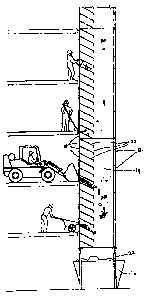
Figure 2 is a schematic, partial side elevation of the refuse chute of fig. 1,
with four building levels shown;
Figure 3 shows a top elevation (3A), front elevation (3B), and side
elevation (3C) of the refuse chute of Figure 1;
Figure 4 shows a front elevation of the refuse chute with varying covers for
the refuse inlets;
Figure 5 shows a perspective view of a stackable chute seotion of the
refuse chute of Figure 1, including a stacking facilitation portion and a
securing
device;
Figure 6 shows a schematic perspective view of a single chute section of a
refuse chute as shown in Figure 1 in, accordance with an =embodiment di the
invention; and
Figures 7A and B show a schematic of a side elevation and top elevation
respectively of two chute sections of the type shown in Figure 6 joined
together.
DESCRIPTION OF PREFERRED EMBODIMENT
The present invention may be implemented In a variety of ways and the
embodiments illustrated are to be considered only illustrative constructions.
Figure 1 is a schematic perspective view of the refuse chute 10_ Refuse
chute 10 is assembled from four ldentical chute sections 12. The chute
sections
12 may be identical and: stacked and secured together at the end faces, as
shown, or be of some other configuration such a-s a nesting arrangement in
which
CA 02636510 2008-07-11
WO 2007/079544 PCT/AU2007/000028
~
the chute sections are joined together through their side walls, ie similar to
telescopically inserted sections. The chute sections 12 can be stacked as high
as
needed for the particular application. Different types of chute sections are
known
from, for example, GB 2,229,427 A, US 3,627,090, and AU 682758, the contents
of which are hereby incorporated by reference.
In this case, the chute sections 12 are of constant quadriiateral cross-
section, made of steel sheets, and removably joined together at their end
faces to
form an enclosed disposal shaft 14, through which refuse fai[s by gravity to a
container 16 below. Refuse is fed into the disposal shaft 14 through refuse
inlets/openings 18.
The concept underiying the invention may best be appreciated by
reference to Figure 2. Each chute section 12 has multiple openings 18. These
multple openings 18 allow refuse to be fed into the refuse chute 10 at
different
heights on the same level; for example, by the tray of a boboat or $imilor
vehicle,
by hand, wheelbarrow, or by sweeping the refuse into the shaft 14. It will be
appreciated that dependent on the situation, only some of the chute sections
12
will have multiple openings 18, or even single openings.
Associated with each refuse inlet 1$ is a baffle 20 extending into the
disposal shaft, inclined at an angle to the height axis of chute sections 12
and in
particular inclined at an obtuse angle relative to the refuse inlet 18 with
which it is
associated. Each baffle, which is preferably a planar sheet metal plate, is
fixed to
its associated refuse inlet 18 at or near the lower edge of that refuse inlet
18. The
baffle 20 provides a slide such as to assist in gravity feeding the refuse
into the
disposal shaft 14, and further minimises the risk of refuse from higher tevels
harming a user placing refuse into the chute 10 at lower levels. The baffle 20
also
provides a shelter or protection to the refuse inlet 18 below the opening with
which the baffle 20 is associated. The incline and length of the baffle 20
shown is
such that the end of the baffle 20 furthest from the refuse inlet 18 is on ~
horizontal plane with the upper edge of the refuse inlet 18 below the baffle
(see
line A). The baffles have a horizont4 reinforcing lip 24 dependent from the
end of
each baffle 20 and extending the entire width thereof.
Each chute section 12 may have multiple baffles 20 (say four to six or
more baffles) which may have to be lifted into place by a lifting device due
to its
CA 02636510 2008-07-11
WO 2007/079544 PCT/AU2007/000028
7'
weight. fiowever, smaller sections 12 having one or two baffles 20 can be
-manufactured and lifted by hand and secured in place manually.
Also shown in Figure 2 is one example of struts 22 by which refuse chute
is held above the container 16. The refuse chute 10 is also able to be
5 attached to the building or to the building site scaffolding or any other
structure,
as known to those in the art, keeping it securely in position using the
securing or
attachment points 28, shown in Figures 3 and 4.
Figure U shows the top view of the refuse chute 10 along a fine A of
Figure 3C (a simplified reproduction of the side elevation of the refuse chute
10
10 from Figure 2). The length of the baffles 20 in this embodiment is about
40% to
60% (or sufficient to cover from above the length of the arm of a person
disposing
refuse) into the chute 10 of the length of the chute seGtions 12, 6nd as shown
in
Figure 3B they extend across the width of the chute sections 12.
The refuse Inlets 18 can optionally be provided with a cover 26, as shown
in Figure 4. The cover can be either a flap 26b through which refuse can still
be
placed such as a shade cloth type material or rubber, or a steel cover 26a
removably secured to the opening 18 to seal it temporarily from use.
Figure 5 shows a possible configuration for an individual chute section 12
which stacks to form a refuse chute 10 in an end-to-end configuration. The
body
and baffle 20 configuration is the same as shown in previous figures. However,
the chute section 12 includes a stacking facilitation portion 30 which is a
three
sided component placed inside the walls of the chute section 12 so as to fit
in a
nesting manner into the top of the chute section 12 below it. The stacking
portion
has an open front corresponding to the side of the refuse chute 10 which has
25 provided refuse inlets 18, extends along a portion of the side walls of the
chute
section 12, and along the wall distal and parallel to the wall which has the
openings 18 provided. In the case of a refuse chute 10 of circular cross-
section,
the stacking portion 30 would be of an arc-shape. The stacking facilitation
portion
30 could also be provided in a refuse chute 10 in which the chute sections 12
are
30 nested.
Further, a securing device 32, here shown as a chain, is provided on the
top edge of the refuse chute section 12_ This chain 32 may be attached to the
scaffolding or other structure against which the refuse chute 10 is supported,
or
CA 02636510 2008-07-11
WO 2007/079544 PCT/AU2007/000028
8
may Iink to immediately adjacent chute sections 12. The chain 32 can be used
in
addition, or as an alternative to, attachment points 28.
The most preferred configuration for the chute sections 12 and refuse
chute 10 is shown in Figures 6 and 7, which show chute sections 12 which have
a
0 single baffle 20 associated with a single opening 18. The chute section 12
is of
the type in which each chute section 12 is intended to be stacked in an end-to-
end arrangement to form a refuse chute 10. The upper and lower edges of the
chute section 12 have a lip 33 extending perpendicularly to the walls of the
chute
section 12 which correspond with similar lips on immediately adjacent chute
sections 12. The adjacent chute sections 12 are secured together with any
suitable means via attachment points 34 on the lip 33, but in the illustration
of
Figure 7, they are joined by bolts 36.
The present invention is not limited in.application to the refuse chute
configuration described. For example, the chute sections may be made out of
any
suitabie material and different cross-sectional shapes may be used to make up
the completed refuse chute depending on the needs of the application. Whilst
sheet steel would most commonly be used, reinforced plastics materials or
wooden constructions are not excluded from consideration, as are mixed-
material
solutions, eg the chute seclions being manufactured from sheet metal, and the
baffles from steel (or otherwise reinforced) plastics materials. Similarly,
steel
sheet baffles may be lined or otherwise coated/covered with abrasion-resistant
and/or sound-absorbing materials such as to minimise noise impact upon refuse
failing from above and hitting the baffle(s).