Note: Descriptions are shown in the official language in which they were submitted.
CA 02636935 2008-07-08
TITLE OF THE INVENTION
Toilet Seat Elevator Assembly
FIELD OF THE INVENTION
[0001] The present invention relates generally to toilet seat elevators, and
more
particularly to a toilet seat elevator assembly that is easily installed and
removed with
respect to a toilet bowl.
BACKGROUND OF THE INVENTION
[0002] Over the years, toilet bowls have been manufactured in many different
sizes
and shapes. More recently, the plumbing industry has become conscious of the
necessity
for the interchangeability of products and thus the dimensions of the bowl
have become
increasingly limited by consensus standards. One of the standards dictates
that the seat
on a toilet bowl, when in a horizontal or lowered position, be located between
15 and 16
inches above the floor. The conventional 15-16 inch toilet seat height is
common for both
residential and commercial bowls and is generally adapted to accommodate needs
of the
majority of people.
[0003] However, many people with physical limitations and disabilities have
difficulty
accessing the toilet seat at the conventional height and thus require a seat
which is raised
1-5 inches or higher comparative to standards. To meet this need, various seat
elevator
-1-
CA 02636935 2008-07-08
arrangeinents have been developed. These elevators raise the level of the
horizontal seat
and reduce the human body bending required to effectively use the bowl.
[0004) Toilet bowl elevators of various sorts have been commercially available
for
many years. Many of these elevators must be attached to the bowl in such a way
that the
bowl is restricted in its use or the elevator simply sits on the bowl.
Elevators that are
permanently attached or bolted to the bowl either through the conventional
seat
attachment holes or to the annular rim around the top of the bowl create many
areas
between the bowl and the elevator which are difficult to clean, while adding
moisture and
dirt collecting areas in the elevator itself. The result is an unsanitary
manner by which
the elevators are attached to the toilet bowl. By permanently attaching the
elevator to the
rim or tail of the bowl, its use is thereafter restricted to seated endeavors.
In this manner,
the possible utilization of the bowl as a standing urinal for the male users
becomes very
difficult or is totally eliminated.
[0005] The prior art seat elevators that merely sit on the bowl or are
attached by clips,
so as to be removed for cleaning, tend to be unstable in use. It should be
noted that in
view of the limitations of persons disposed to use toilet elevators, stability
and security
are of primary importance. Another serious drawback of the conventional
elevators is
that in view of the typically permanent attachment to the bowl, adjustment of
the elevator
with respect to the bowl is often not possible. This makes it difficult to
adapt usage of
the same elevator to various sizes and configurations of the bowls. In view of
the above,
it has been a long felt and unsolved need for a toilet seat elevator which can
be easily
-2-
CA 02636935 2008-07-08
attached to or removed from a bowl so as to simplify cleaning and replacement
as well as
facilitate use of the elevator with bowls of various configurations
BRIEF SUMMARY OF THE INVENTION
[00061 According to one aspect of the invention, a toilet seat elevator
assembly
includes a seat elevator and a bracket for removably connecting the seat
elevator to a
toilet bowl. The seat elevator has a support portion for resting on the toilet
bowl and a
mounting portion that extends rearwardly of the support portion. The mounting
portion
has at least one mounting projection that extends inwardly. The bracket
includes a
bottom wall that is adapted for securement to the toilet bowl and spaced
bracket side
walls extending upwardly from the bottom wall. Each bracket side wall has
forward and
rear edges that extend upwardly from the bottom wall and an elongate slot that
extends
within each bracket side wall between the forward and rear edges. Each
elongate slot is
adapted for slidably receiving the at least one mounting projection of the
mounting
portion to adjust the seat elevator between a retracted position to
accommodate various
configurations of respective toilet bowls.
-3-
CA 02636935 2008-07-08
BRIEF DESCRIPTION OF THE DRAWINGS
[0007] The foregoing summary as well as the following detailed description of
the
preferred embodiments of the present invention will be best understood when
considered
in conjunction with the accompanying drawings, wherein like designations
denote like
elements throughout the drawings, and wherein:
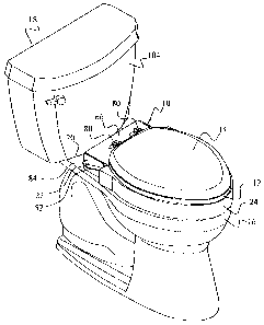
(0008] FIG. 1 is an isometric view of a toilet seat elevator assembly mounted
on a
conventional toilet in accordance with the present invention;
[0009] FIG. 2 is an exploded isometric view of the elevator assembly of FIG. 1
for
mounting to the toilet;
[0010] FIG. 3 is an isometric view of the elevator assembly partially
assembled to the
toilet and accompanying toilet seat and lid;
[0011] FIG. 4 is a side elevational view of the elevator assembly and a
portion of the
toilet, showing the manner in which the seat elevator is attached to a
mounting bracket
which is in turn mounted on the toilet bowl;
[0012] FIG. 5 is a side elevational view similar to FIG. 4 showing further
steps of
installation of the seat elevator with accompanying toilet seat and lid to the
mounting
bracket;
-4-
CA 02636935 2008-07-08
[0013] FIG. 5A is an enlarged partial side elevational view of FIG. 5 showing
movement of a mounting projection within an elongate slot of the mounting
bracket
during installation of the seat elevator;
[0014] FIG. 6 is an isometric view of a seat elevator with accompanying toilet
seat and
lid in a horizontal position that may be assumed during installation;
[0015] FIG. 7 is a side elevational view similar to FIG. 5 showing further
movement of
the seat elevator with accompanying toilet seat and lid during installation;
[0016] FIG. 8 is a side elevational view of the elevator assembly in the
installed
horizontal lowered position on the toilet bowl;
[0017] FIG. 9 is a side elevational view of the elevator assembly showing the
lid in one
upright position;
[0018] FIG. 10 is a side elevational view showing the seat elevator with
accompanying
toilet seat and lid in another upright position;
[0019] FIG. Il is an enlarged side elevational view of a mounting bracket in
accordance with a further preferred embodiment of the invention;
[0020] FIG. 12 is a side elevational view of an elevator assembly mounted to
the toilet
bowl and showing the manner in which the mounting bracket can accommodate seat
elevators of varying height;
-5-
CA 02636935 2008-07-08
[0021] FIG. 13 is an enlarged side elevational view of a mounting bracket in
accordance with yet a further preferred embodiment of the invention;
[00221 FIG. 14 is an enlarged side elevational view of a mounting bracket in
accordance with another preferred embodiment of the invention;
[0023] FIG. 15 is an enlarged side elevational view of a mounting bracket in
accordance with still another preferred embodiment of the invention;
100241 FIG. 16 is an enlarged side elevational view of a mounting bracket in
accordance with an additional preferred embodiment of the invention; and
100251 FIG. 17 is a rear isometric view of a toilet seat elevator assembly in
accordance
with another preferred embodiment of the invention;
[00261 FIG. 18 is a rear isometric view of the elevator assembly of FIG. 17 in
a
partially raised position with a handle portion removed;
[0027] FIG. 19 is a rear isometric exploded view of the elevator assembly of
FIG. 17;
[00281 FIG. 20 is a bottom isometric exploded view of the elevator assembly of
FIG.
17 with the handle removed;
[0029J FIG. 21 is a top plan view of the elevator assembly;
[00301 FIG. 22 is a sectional view of the elevator assembly taken along
section line 22-
22 of FIG. 21;
-6-
CA 02636935 2008-07-08
[0031] FIG. 23 is a sectional view of the elevator assembly taken along
section line 23-
23 of FIG. 21;
[0032] FIG. 24 is a top plan view of the elevator assembly of FIG. 17
installed on a
toilet bowl showing adjustment for elongated and standard bowl configurations;
[0033] FIG. 25 is a side elevational view in partial cross section taken along
section
line 25-25 of FIG. 24 and showing an attached toilet seat and lid;
[0034] FIG. 26 is a rear isometric view of a mounting bracket in accordance
with
another preferred embodiment of the invention;
[0035] FIG. 27 is a rear isometric view of a mounting bracket in accordance
with a
further preferred embodiment of the invention;
[0036] FIG. 28 is a rear isometric view of a mounting bracket in accordance
with yet
another preferred embodiment of the invention; and
[0037] FIG. 29 is a rear isometric view of a toilet seat elevator assembly in
accordance
with yet a further preferred embodiment of the invention.
[0038] It is noted that the drawings are intended to depict only typical or
exemplary
embodiments of the invention and thus may not be necessarily to scale.
Accordingly, the
drawings should not be considered as limiting the scope of the invention. The
invention
will now be described in greater detail with reference to the accompanying
drawings.
-7-
CA 02636935 2008-07-08
DETAILED DESCRIPTION OF THE INVENTION
[0039] Referring to the drawings and to FIGS. I and 2 in particular, a toilet
seat
elevator assembly 10 in accordance with an exemplary embodiment of the present
invention is illustrated. The elevator assembly 10 serves to increase the
height of a
conventional toilet seat 12 and lid 14 with respect to a toilet bowl 16 of a
conventional
toilet 18 to accommodate users who may otherwise experience difficultly with
toilet seats
of conventional height. The elevator assembly 10 preferably includes a
mounting bracket
20 connected to a seat mounting area 22 of the toilet bowl 16 and a seat
elevator 24
removably connected to the mounting bracket 20.
[0040] The mounting bracket 20 preferably has a bottom wall 26 and spaced side
walls
or walls 28, 30 extending upwardly from the bottom wall. The bottom wall 26
includes a
rear edge 32 and spaced slots 34, 36 that preferably extend in a parallel
manner with
respect to the rear edge. The slots 34 and 36 are in alignment with spaced
openings 38
and 40, respectively, of the toilet bowl 16 when the mounting bracket 20 is
positioned on
the seat mounting area 22 of the toilet bowl 16. The slots 34, 36 and openings
38, 40 are
sized for accepting many types of conventional fasteners which can be in the
form of
screws or bolts 42. Nuts 44 are received on the screws 42 underneath the seat
mounting
area 22 in a conventional manner for securing the mounting bracket 20 to the
toilet bowl
16. The lateral extension of the slots 34, 36 accommodates different toilet
bowl hole
spacings and sizes that may be present because of variations in tolerances
during
-8-
CA 02636935 2008-07-08
manufacture as well as different toilet bowl configurations or designs.
Accordingly, the
mounting bracket 20 is adaptable for use with a wide variety of toilet bowl
shapes and
sizes. Other attachment means including adhesives, clamps, and so on may
additionally
or alternatively be used to secure the bracket 20 to the toilet bowl 16.
[0041] With additional reference to FIG. 5A, each side wall 28, 30 (only side
wall 28
shown in FIG. 5A) of the mounting bracket 20 preferably includes a forward
edge 46 and
a rear edge 48 that extend upwardly from the bottom wall 26 and an upper edge
50 that
extends between the forward and rear edges. An elongate slot 52 extends
diagonally
from a first slot position 54 proximal the forward edge 46 and upper edge 50
to a second
slot position 56 proximal the rear edge 48 and bottom wall 26. A first slot
segment 58
extends from the upper edge 50 of the side wall to the elongate slot 52,
preferably
between the first and second slot positions. A second slot segment 60 is
spaced
rearwardly of the first slot segment 58 and preferably extends toward the
upper edge 50
from the second slot position 56 of the elongate slot 52. The purpose of the
elongate slot
and slot segments will be described in greater detail below.
[0042] With particular reference to FIG. 2, the seat elevator 24 is preferably
of
lightweight, hollow construction and includes a generally ring-shaped seat
support
portion 62 that is adapted to rest on or otherwise be supported by an upper
surface 64 of
the toilet bowl 16 and an elevator mounting portion 66 that extends rearwardly
of the
ring-shaped portion 62. Preferably, the seat support portion 62 and mounting
portion 66
form a unitary structure but may alternatively be formed separately and
connected
-9-
CA 02636935 2008-07-08
together through mechanical fasteners, brackets, adhesives, welding, or any
other well-
known connection means.
[0043] The mounting portion 66 includes a rear wall 68 and spaced slots 70, 72
that
preferably extend parallel with the rear wall. The slots 70 and 72 preferably
extend
through the mounting portion 66 and are in alignment with spaced openings 74
and 76,
respectively, of conventional seat hinges 78 when the seat 12 and lid 14 are
aligned over
the seat support portion 62. The slots 70, 72 and openings 74, 76 are sized
for accepting
screws or bolts 80. Nuts 82 are received on the screws 80 underneath the
mounting
portion 66 in a conventional manner for securing the mounting bracket 20 to
the toilet
bowl 16. If desired, the nuts 82 may be recessed into the bottom of the
mounting portion
66. The lateral extension of the slots 70, 72 accommodate different toilet
seat hinge
spacings due to variations in tolerances during manufacture as well as
different toilet seat
and/or hinge configurations. In accordance with a further embodiment of the
invention,
the slots 70, 72 and nuts 82 may be replaced with threaded openings formed in
the
mounting portion 66 to directly receive the screws 80.
[0044) The mounting portion 66 also includes mounting projections 84 and 86
that
extend outwardly from opposite side mounting walls 88 and 90, respectively.
Each
mounting projection 84, 86 is preferably cylindrical in shape and is sized for
reception
into one of the elongate slots 52 and its associated slot segments 58, 60.
Spaced grooves
92, 94 are formed in the seat elevator 24 at the junction of the ring-shaped
portion 62 and
-10-
CA 02636935 2008-07-08
the mounting portion 66 for receiving the side walls 28, 30 of the mounting
bracket 20
when the seat elevator 24 is connected to the mounting bracket 20.
[0045] Referring now to FIGS. 3-8, a method of connecting the elevator
assembly 10
to the toilet bowl 16 is illustrated. The mounting bracket 20 is first secured
to the seat
mounting area 22 of the toilet bowl 16 in the manner as previously described,
as shown in
FIGS. 3 and 4. For convenience, the toilet seat 12 and lid 14 may be pre-
mounted to the
seat elevator 24, so as to form a respective sub-assembly in the manner as
previously
described before connecting the seat elevator to the mounting bracket 20. The
seat
elevator sub-assembly, is then moved over the toilet bowl 16 until the
mounting
projections 84, 86 are aligned with the first slot segments 58 of the mounting
bracket side
walls 28, 30. Once aligned, the seat elevator 24 is then lowered in a
direction as
represented by arrow 96 (see FIG. 4), until the mounting projections 84, 86
are positioned
in the respective elongate slots 52. Subsequently, the seat elevator 24 is
slid downwardly
and rearwardly toward the second slot position 56, as denoted by arrow 98 in
FIG. 5A,
with the mounting projections 84, 86 guiding movement of the seat elevator 24
along
their respective elongate slots 52. The rotational ability of the mounting
projections 84,
86 within their respective slots 52, as represented by an arrow 100 in FIG.
5A, allows the
seat elevator 24 to be installed on the bracket 20 at an adjustable angle A
(see FIG. 5)
convenient to the installer. In this manner, the seat elevator 24 can be
connected to the
bracket 20 in a more natural upright position. This reduces the possibility of
back strain
or related injuries that may otherwise occur if the installer or user is
required to bend over
-11-
CA 02636935 2008-07-08
. =
during installation. As shown in FIG. 6, if an attempt is made to install the
seat elevator
in a horizontal position, further rearward movement of the mounting
projections 84, 86 in
their respective slots 52 is inhibited due to the sloping nature of the slots
and the position
of the mounting projections on the mounting portion 66 of the seat elevator
24.
Accordingly, the present embodiment discourages a user or installer from
assuming a
potentially unsafe bent-over position during installation of the seat elevator
24 to the
mounting bracket 20.
[0046] As shown in FIG. 7, when the mounting projections 84, 86 have reached
the
second slot position 56, the seat elevator 24 and accompanying toilet seat 14
and lid 12
can be rotated in a direction, as represented by arrow 102, to the lowered or
horizontal
position shown in FIG. 8. In this position, the mounting projections 84, 86
are located at
the upper part of the respective second slot segments 60. In this manner the
seat elevator
24 is secured against sliding movement along the elongate slots 52.
Subsequently, as
shown in FIG. 9, the lid 14 can be rotated to an open position for use.
Likewise, as
shown in FIG. 10, the seat elevator with the associated seat and lid can be
slid diagonally
and forwardly along the slots 52 until the mounting projections are located at
the first slot
position 54. The seat elevator with the associated seat and lid can then be
rotated so that
the lid 14 rests against the tank 104 of the toilet 18. This stable, over-
center position
ensures that the seat elevator 24 and the accompanying seat and lid can be
moved and
rotated for use as a urinal and/or for cleaning without removal from the
mounting bracket
20. Also, the seat elevator with toilet seat and lid may be easily and
conveniently
- 12-
CA 02636935 2008-07-08
removed from the bracket 20 for cleaning or replacement simply by reversing
the
installation procedure as described above.
[0047] With reference now to FIG. 11, in order to provide even greater
stability in the
upright position, a mounting bracket 110 in accordance with a further
embodiment of the
invention is illustrated. The mounting bracket 110 is similar in construction
to the
mounting bracket 20 of the previous embodiment, with the exception that each
side wall
112 is provided with a third slot segment 114 that extends downwardly from the
elongate
slot 52, preferably from the first slot position 54. When the seat elevator
and
accompanying seat and lid are raised to lean against the tank, as illustrated
in the FIG. 10
position, the mounting projections 84, 86 (projection 84 shown in phantom line
in FIG.
11) are located in the third slot segment 114 of the respective side walls 28,
30. This
secures the seat elevator 24 against undesirable at this time sliding movement
along the
elongate slots 52.
[0048] As shown in FIG. 12, due to the sloping nature of the elongate slot 52,
the
mounting bracket of any of the preceding or following embodiments is
particularly useful
for accommodating seat elevators 24 of various heights "H". When a seat
elevator of a
greater height is used, the mounting projection 84 is located in the elongate
slot 52
somewhere between the first slot position 54 and second slot position 56.
Although not
shown, the other mounting projection 86 would be positioned at a similar
location in the
respective side wall 30. In this position, forward and rear sliding movement
of the seat
elevator 24 with accompanying seat 12 and lid 14 along the toilet bowl 16 is
prevented
- 13 -
CA 02636935 2008-07-08
when the seat elevator is in the lowered position. This is primarily due to
the
engagement between the elevator 24 and the upper surface of the toilet bowl
16.
Accordingly, it is anticipated that the mounting bracket 20 of the present
invention can
accommodate a wide variety of seat elevator heights without modification.
However, it
will be understood that different mounting brackets with different elongate
slot elevations
may be provided for different seat heights when it is desirous to lock the
mounting
projections 84, 86 in their respective second slot segments 60.
[0049] The present invention provides seat elevator arrangement capable of
accommodating various configurations of the toilet bowls. Referring now to
FIG. 13,
wherein a mounting bracket 116 in accordance with a further embodiment of the
invention is illustrated. The mounting bracket 116 is similar in construction
to the
mounting bracket 20 of the previous embodiment, with the exception that each
side wall
118 is provided with a third slot segment 120 that extends upwardly toward the
upper
edge 50 from the elongate slot 52, preferably between the first slot segment
58 and
second slot segment 60. With this arrangement, the mounting bracket 116 can be
mounted on either round or elongate toilet bowls with the mounting projections
84, 86
(only 84 shown in FIG. 13 in phantom line) located in the slot segment 60 for
round toilet
bowls and in the slot segment 120 for elongate toilet bowls. It will be
understood that the
slot segment 120 can be located at a different position than that shown. Still
further,
more than one slot segment 120 may be provided to accommodate a wide variety
of toilet
bowl sizes and configurations.
-14-
CA 02636935 2008-07-08
[0050] Referring now to FIG. 14, a mounting bracket 122 in accordance with
still
another embodiment of the invention is illustrated. The mounting bracket 122
is similar
in construction to the mounting bracket 110 (see FIG. 11) of the previous
embodiment,
with the exception that the first slot segment 58 is in alignment with the
third slot
segment 114. With this arrangement, the seat elevator with accompanying toilet
seat and
lid may be installed in the over-center position, as shown in FIG. 10, without
the need to
lift the seat elevator to the first slot position as in the previous
embodiments. It will
therefore be understood that the first slot segment 58 may be located anywhere
along the
upper edge 50 of the mounting bracket between the first and second slot
positions 54, 56.
It will be further understood that the first slot segment 58 may intersect
with one of the
forward and rear edges 46, 48 instead of the upper edge 50.
100511 Referring now to FIG. 15, a mounting bracket 124 in accordance with
still
further embodiment of the invention is illustrated. The mounting bracket 124
is similar
in construction to the mounting bracket 20 previously described, with the
exception that
each side wall 126 includes a series of slot segments 128 that extend
downwardly from
the elongate slot 56. Each slot segment 128 is preferably semi-circular in
shape for
receiving the mounting projections 84, 86 during assembly or disassembly of
the seat
elevator with respect to the mounting bracket 124. In this embodiment the seat
elevator
can be moved and/or rotated in controlled, discrete stops or positions.
[0052] Referring now to FIG. 16, a mounting bracket 130 in accordance with a
further
embodiment of the invention is illustrated. The mounting bracket 130 is
similar in
-15
CA 02636935 2008-07-08
construction to the mounting bracket 20 previously described, with the
exception that the
side wall 132 includes an elongate slot 134 with a series of steps 136 located
between the
first slot position 54 and second slot position 56. With this arrangement, the
seat elevator
can be moved in controlled, discrete steps during assembly/disassembly.
Furthermore,
the mounting bracket 130 can be adapted to accommodate a wide variety of
toilet bowl
shapes, sizes, and elevator thicknesses.
[00531 Referring now to FIGS. 17-18, an elevator assembly 140 in accordance
with a
further embodiment of the invention is illustrated. The elevator assembly 140
preferably
includes a mounting bracket 142 for connection to a seat mounting area 22 (see
FIG. 25)
of the toilet bowl 16 and a seat elevator 144 removably connected to the
mounting
bracket 142. A support handle 146 can be connected to the mounting bracket 142
for
grasping by a user to facilitate sitting and standing motions. Preferably, the
support
handle 146 comprises a mounting section 150 and handle sections 152, 154 that
extend in
the same direction from the mounting sections. The support handle 146 can be
constructed from a single bar or rod 148 and bent into the shape as shown.
Alternatively,
the mounting section 150 and handle sections 152, 154 can be formed as
separate
elements and joined together through fastening, welding, or other well-known
connection
means. Although the support handle is shown as being generally circular in
cross section,
it will be understood that the support handle may be configured with other
cross sectional
shapes, such as square, rectangular, oval, triangular, hexagonal, and so on.
-16-
CA 02636935 2008-07-08
(0054] With additional reference to FIGS. 19-20, the mounting bracket 142
preferably
has a bottom wall 156 and spaced side panels or walls 158, 160 extending
upwardly from
the bottom wall. The bottom wall 156 includes a rear bracket section 162 that
receives
the mounting section 150 of the support handle 146. As shown, the rear bracket
section
162 is preferably semi-cylindrical in shape for accommodating the respective
shape of the
mounting section 150 of the support handle. However, it will be understood
that the rear
bracket section 162 may be of any shape, and preferably of a shape that is
complementary
to the shape of the mounting section 150. The support handle 146 can be
connected to
the rear bracket section 162 through conventional connecting means, such as
fasteners,
adhesive bonding, welding, clamps, and so on and/or may be adjustably fixed
for
accommodating the needs of different users.
(0055] Spaced slots 164, 166 preferably extend in a parallel manner with
respect to the
rear bracket section 162. The slots 164, 166 are in alignment with spaced
openings 38
and 40 (see FIG. 2), respectively, of the toilet bowl 16 when the mounting
bracket 142 is
positioned on the seat mounting area 22 of the toilet bowl 16, as previously
described.
The slots 164, 166 and openings 38, 40 are sized for accepting many types of
conventional fasteners which can be in the form of screws or bolts 42. Nuts 44
are
received on the screws 42 underneath the seat mounting area 22 (see FIG. 2) in
a
conventional manner for securing the mounting bracket 142 to the toilet bowl
16. The
lateral extension of the slots 164, 166 accommodates different toilet bowl
hole spacings
and sizes that may be present because of variations in tolerances during
manufacture as
-17-
CA 02636935 2008-07-08
well as different toilet bowl configurations or designs. Accordingly, the
mounting
bracket 142 is adaptable for use with a wide variety of toilet bowl shapes and
sizes.
Other attachment means including adhesives, clamps, and so on may additionally
or
alternatively be used to secure the bracket 142 to the toilet bowl 16.
100561 As best shown in FIG. 20, the bottom wall 156 also preferably includes
a
depression 165 that extends around the slots 164, 166 and a ridge 167 that
borders the
depression 165. Reinforcing ribs 169 preferably crisscross through the
depression to
strengthen the bottom wall 156.
[0057] As best shown in FIG. 19, each side wall 158, 160 of the mounting
bracket 142
preferably includes a forward edge 168 and a rear edge 170 that extend
upwardly from
the bottom wall 156 and an upper edge 172 that extends between the forward and
rear
edges. An elongate slot 174 preferably extends diagonally from a first slot
position 176
proximal the forward edge 168 and upper edge 172 to a second slot position 178
proximal the rear edge 170 and bottom wall 156. A first slot segment 180
extends from
the upper edge 172 of the side wall to the elongate slot 174, preferably
between the first
and second slot positions. A second slot segment 182 is spaced rearwardly of
the first
slot segment 180 and preferably extends transversely relative to the elongate
slot 174
toward the upper edge 172 from the second slot position 178 of the elongate
slot 174. A
third slot segment 184 is located between the first and second slot segments
and
preferably extends transversely to the elongate slot 174 toward the upper edge
172. As
shown, the third slot segment 184 is in the form of a groove or indentation
and is
-18-
CA 02636935 2008-07-08
preferably at the same height of the second slot segment 182 and provided to
accommodate different bowl sizes, as will be described in greater detail
below. It will be
understood that the first, second and third slot segments may extend in other
directions
from the elongate slot 174.
100581 Turning again to FIGS. 19-20, each side wall 158, 160 also preferably
includes
a depression 186 that extends around the elongate slot 174 as well as the
first, second and
third slot segments. Inner and outer ridges 188 and 190, respectively, border
the
depression 186. Reinforcing ribs 192 preferably extend through the depression
between
the outer and inner ridges to strengthen the side walls 158, 160.
[00591 The mounting bracket 142 is preferably constructed of an injection-
molded
plastic material. However, it will be understood that the bracket can be
formed using
other molding or forming techniques as well as other materials, such as
metals,
composites, ceramics, and so on.
[0060] Referring now to FIGS. 19-23, the seat elevator 144 is preferably of
lightweight, hollow construction and includes a generally ring-shaped seat
support
portion 194 that is adapted to rest on or otherwise be supported by an upper
surface 64
(see FIGS. 24-25) of the toilet bowl 16 and an elevator mounting portion 196
that extends
rearwardly of the support portion 194. In one embodiment of the invention, the
seat
elevator 144 is constructed of a lower shell section 198 and an upper shell
section 200,
each including a segment of the ring-shaped support portion and integrally
formed
- 19-
CA 02636935 2008-07-08
elevator mounting portion. As best shown in FIGS. 20 and 23, in this
embodiment,
hollow stubs 202 are formed in the lower shell portion 198 and solid shafts
204 are
formed in the upper shell portion 200 in alignment with the stubs 202. A
fastener (not
shown), such as a screw, can be inserted into each hollow stub 202 and screwed
into its
corresponding shaft 204 for securing the upper and lower shell portions
together. An
inner wall 206 extends downwardly from the upper shell portion 200 and past
the lower
shell portion 198 to form a lip 208 which can be used for properly locating
and
positioning the seat elevator 144 on the toilet bowl 16.
[0061] It will be understood that the lower and upper shell portions 198, 200
can be
connected together through other connection means such as brackets, adhesives,
welding,
and so on. It will be further understood that the entire seat elevator 144 can
be of a
unitary structure for example through a blow-molding operation. In accordance
with yet
a further embodiment of the invention, the seat elevator 144 can be formed as
a partially
solid or completely solid structure with little or no hollow interior space.
[0062] The mounting portion 196 includes a rear wall 210 and spaced grooves
212,
214 that preferably extend forwardly from the rear wall 210. The grooves 212
and 214
are spaced to receive the side walls 158 and 160, respectively, of the
mounting bracket
142 when the seat elevator 144 is installed on the mounting bracket.
[0063] The mounting portion 196 also includes side mounting walls 216 and 218
that
extend rearwardly from the support portion 194 and mounting projections 220
and 222
-20-
CA 02636935 2008-07-08
that extend inwardly toward each other from their respective side mounting
walls 216,
218. Each mounting projection 220, 222 preferably includes a substantially
cylindrical
shaft 224 which can be hollow and a head 226 formed at the outer free end of
the shaft.
However, it will be understood that the shaft 224 can be of different
configuration and/or
that the head 226 can be eliminated. Preferably, the shaft 224 is sized for
reception into
one of the elongate slots 174 and its associated slot segments 180, 182 and
184 in a
similar manner as described with respect to the previous embodiments.
[0064] In accordance with yet a further embodiment of the invention, the
mounting
projections can be in the form of spring-loaded plungers, and/or flexible or
compressible
shafts. Alternatively, the side walls 216, 218 of the mounting portion 196
and/or the side
walls 158, 160 of the mounting bracket 142 can have some measure of resilience
to
ensure adequate engagement of the mounting projections with the slot segments
during
use.
[0065] The method of connecting the elevator assembly 140 to the toilet bowl
16 is
similar to the method previously described and therefore will not be further
elaborated
on. With this arrangement, the mounting bracket 142 can be smaller in size
than the
mounting brackets of the previous embodiments since the mounting projections
220, 222
extend inwardly, thus conserving space on the toilet bowl while reducing
material and it's
associated costs.
-21-
CA 02636935 2008-07-08
100661 Referring now to FIGS. 24-25, the provision of the mounting bracket 142
with
the slot segments 182 and 184 permits the elevator assembly 140 to be
installed on end
used with both elongate toilet bowls 16 or standard sized toilet bowls 16A
(represented
by phantom line in FIGS. 24 and 25). As shown, when the shaft 224 is located
in the
third or forward slot segment 184, the seat elevator is in the extended
position so that a
forward end 228 of the seat elevator 144 is in alignment with a forward end
230 of the
elongate toilet bowl 16. Likewise, when the shaft 224 (shown in phantom line)
is located
in the second or rearward-most slot segment 182, the seat elevator is in the
retracted
position so that a forward end 228A (shown in phantom line) of the seat
elevator 144 is in
alignment with a forward end 230A (shown in phantom line) of the standard size
toilet
bowl 16A. Although two sizes of the toilet bowls are being discussed in the
embodiment
of the invention, it should be clear that the invention is capable of
accommodating the
toilet bowls of the many other shapes and sizes. Accordingly, a wide variety
of toilet
bowl sizes and configurations can be accommodated. It will be understood that
the slot
segments can be located at different positions than that shown. Still further,
more or less
slot segments may be provided.
100671 In accordance with a further embodiment of the invention, the elongate
slot 174
may be eliminated and the slot segments may be in the form of openings and/or
depressions of any desired shape in each side wall 158, 160. This embodiment
is
especially advantageous when used with spring-loaded or resilient plungers for
the
mounting projections.
-22-
CA 02636935 2008-07-08
[0068] Referring now to FIG. 26, a mounting bracket 232 in accordance with a
further
embodiment of the invention is illustrated. The mounting bracket 232 is
similar in
construction to the mounting bracket 142 of the previous embodiment, with the
exception
that each side wall 234, 236 is provided with a wall segment 238 that covers a
portion of
the elongate slot 174. In the illustrated embodiment, the wall segment 238
covers the
second slot segment 182. The wall segments 238 are preferably constructed, so
as to be
removable from the side walls 234, 236 through any well known removable
connection
means such as perforations or grooves for punching out the wall segment,
fasteners,
clainps, temporary adhesive, and so on. The removable wall segments 238 are
useful
when the mounting bracket 232 and seat elevator 144 are to be associated with
elongated
toilet bowls only. In this manner, a user is prevented from inadvertently
moving the seat
elevator in the standard bowl position. This is because such position is
effectively
blocked by the wall segments 238. When the seat elevator 144 will be used with
a
standard toilet bowl, the wall segments 238 can simply be removed, so as to
enable to
locate the seat elevator in the standard bowl position.
[0069] Referring now to FIG. 27, a mounting bracket 240 in accordance with a
further
embodiment of the invention is illustrated. The mounting bracket 240 is
similar in
construction to the mounting bracket 232 of the previous embodiment, with the
exception
that each side wall 242, 244 is provided with a wall segment 246 that extends
across the
elongate slot 174. In this manner, a portion of the elongate slot 174 facing
the interior of
the mounting bracket is blocked. Thus, outwardly facing the first slot segment
180,
-23-
CA 02636935 2008-07-08
second slot segment 182 and third slot segment 184 are formed. The wall
segment 246
can be either removably connected or permanently attached to the side walls
242, 244. In
any event, in this embodiment, shorter inwardly extending mounting projections
220, 222
(see FIG. 19) can be used to slide along the elongate slot 174 and slot
segments. This
arrangement is especially advantageous for use with mounting projections that
resiliently
engage the wall segment 246 within the slot and slot segments. In this
embodiment, the
mounting projections can be in the form of spring-loaded plunger mechanisms,
flexible
shafts, resilient side walls, and so on, as previously discussed.
[0070] Referring now to FIG. 28, a mounting bracket 250 in accordance with a
further
embodiment of the invention is illustrated. The mounting bracket 250 is
similar in
construction to the mounting bracket 240 of the previous embodiment, with the
exception
that each side wall 252, 254 is provided with an outer wall segment 256 that
extends
across the elongate slot 174. In this manner, a portion of the elongate slot
174 facing the
exterior of the mounting bracket is blocked. Thus, inwardly facing the first
slot segment
180, second slot segment 182 and third slot segment 184 are formed. As in the
previous
embodiment, the wall segment 256 can be either removably connected or
permanently
attached to the side walls 252, 254. In any event, shorter outwardly extending
mounting
projections, such as 84 and 86 (FIG. 2) can be used to slide along the
inwardly facing
elongate slot 174 and the respective slot segments. This arrangement is
especially
advantageous for use with mounting projections that resiliently engage the
wall segment
-24-
CA 02636935 2008-07-08
256 within the slot and slot segments through spring-loaded plunger
mechanisms, flexible
shafts, resilient side walls, and so on, as previously discussed.
[0071] Turning now to FIG. 29, an elevator assembly 260 in accordance with a
further
embodiment of the invention is illustrated. The elevator assembly 260 is
similar in
construction to the elevator assembly 140 previously described, with the
exception that
the inwardly extending mounting projections 220, 222 (FIG. 19) are replaced
with a
single mounting projection or shaft 264 that extends between the side walls
216 and 218
of the seat elevator 262. The shaft 264 engages the elongate slot 174 and slot
segments
180, 182 and 184 in a similar manner as the projections 220, 222 previously
described.
On the other hand, this embodiment in some instances provides greater
stability during
installation and adjustment than the previous embodiments. In a further
embodiment, the
shaft 264 can be integrally formed with the lower and upper shell portions
198, 200 of the
seat elevator 262. However, it may alternatively be separately formed and
attached to the
side walls 216, 218 of the seat elevator in a conventional manner.
[0072] It will be understood that the term "preferably" as used throughout the
specification refers to one or more exemplary embodiments of the invention and
therefore
is not to be interpreted in any limiting sense. It will be further understood
that the term
"connect" and its various derivatives as may be used throughout the
specification refer to
components that may be joined together either directly or through one or more
intermediate members. In addition, terms of orientation and/or position as may
be used
25-
CA 02636935 2008-07-08
throughout the specification relate to relative rather than absolute
orientations and/or
positions.
[0073] It will be appreciated by those skilled in the art that changes could
be made to
the embodiments described above without departing from the broad inventive
concept
thereof. By way of example, only one of the side walls may be provided with
the first
slot segment while the other side wall is void of the first slot segment. In
this manner,
one of the mounting projections may be directly inserted into the elongate
slot while the
other mounting projection is inserted into the elongate slot via the first
slot segment. It
will be understood, therefore, that this invention is not limited to the
particular
embodiments disclosed, but is intended to cover modifications within the
spirit and scope
of the present invention as defined by the appended claims.
-26-