Note: Descriptions are shown in the official language in which they were submitted.
CA 02637061 2013-02-14
SEALANT INTEGRATED FUEL CELL COMPONENTS AND METHODS
AND SYSTEMS FOR PRODUCING THE SAME
FIELD OF THE INVENTION:
[0001] The present invention relates to a method and a composition for
bonding and
sealing components of an electrochemical cell, such as a fuel cell, and an
electrochemical cell
formed therefrom. More particularly, the present invention relates to a
composition, method and
design for making an integrated, molded seal on a fuel cell membrane electrode
assembly using a
liquid sealant.
BRIEF DESCRIPTION OF RELATED TECHNOLOGY:
[0002] Although there are various known types of electrochemical cells,
one common
type is a fuel cell, such as a proton exchange membrane ("PEM") fuel cell. The
PEM fuel cell
contains a membrane electrode assembly ("MEA") provided between two flow field
plates or
bipolar plates. Gaskets are used between the bipolar plates and the MEA to
provide seals thereat.
Additionally, since an individual PEM fuel cell typically provides relatively
low voltage or
power, multiple PEM fuel cells are stacked to increase the overall electrical
output of the
resulting fuel cell assembly. Sealing is also required between the individual
PEM fuel cells.
Moreover, cooling plates are also typically provided to control temperature
within the fuel cell.
Such plates are also sealed to prevent leakage within the fuel cell assembly.
After assembling the
fuel cell stack is clamped to secure the assembly.
[0003] As described in U.S. Patent No. 6,057,054, liquid silicone rubbers
have been
proposed to be molded onto membrane electrode assemblies. Such silicone
compositions,
however, degrade before the desired operating lifetime of the fuel cell is
achieved. Also, such
silicone rubbers release materials that contaminate the fuel cell, thereby
adversely affecting the
performance of the fuel cell. Molding of liquid silicone rubber onto separator
plates is also
described in U.S. Patent No. 5,264,299. To increase the operating lifetime,
more durable
1
CA 02637061 2008-07-14
WO 2007/084472 PCT/US2007/001064
'elastoniers such as fluoroelastomers, as described in U.S. Patent No.
6,165,634, and polyolefin
hydrocarbons, as described in -U.S. Patent No. 6,159,628, have been proposed
to bond the surface
of fuel cell components. These compositions, however, do not impregnate porous
structures
such as the gas diffusion layer. The viscosities of these thermoplastic and
fluoroelastomers
compositions are also too high for injection molding without damaging the
substrate or
impregnating the porous structure.
[00041 = U.S. Patent Application Publication No. US 2005/0263246 Al
describes a method
for making an edge-seal on a membrane electrode assembly that impregnates the
gas diffusion
layer using a thermoplastic film having melting point or a glass transition
temperature of about
100 C. Such a method is problematic because the maximum temperature a proton
exchange
membrane can be exposed to will limit the melt processing temperature. The
seal will then limit
the upper operating temperature of the fuel cell. For example, proton exchange
membranes can
typically only be exposed to a maximum temperature of 130'C, while normally
operating at a
temperature of at least 90 C. Thus, the normal and maximum operating
temperatures of fuel
cells will be limited by the bonding methods of this disclosure.
[00051 U.S. Patent No. 6,884,537 described the use of rubber gaskets with
sealing beads
for sealing fuel cell components. The gaskets are secured to the fuel cell
components through .
the use of layers of adhesive to prevent movement or slippage of the gaskets.
Similarly,
International Patent Publication Nos. WO 2004/061338 Al and WO 2004/079839 A2
describe
the use of multi-piece and single-piece gaskets for sealing fuel cell
components. The gaskets are
secured to the fuel cell components through use of an adhesive. The placement
of the adhesives
and the gaskets are not only time consuming, but problematic because
misalignment may cause
leakage and loss of performance of the fuel cell.
[0006] U.S. Patent No. 6,875,534 describes a cured-in-place composition
for sealing a
periphery of a fuel cell separator plate. The cured-in-place composition
includes a
polyisobutylene polymer having a terminal ally' radial at each end, an
organopolysiloxane, an
organohydrogenpolysiloxane having at least two hydrogen atoms each attached to
a silicon atom
and a platinum catalyst. U.S. Patent No. 6,451,468 describes a formed-in-place
composition for
sealing a separator, an electrode or an ion exchange membrane of a fuel cell.
The formed-in-
2
CA 02637061 2008-07-14
WO 2007/084472 PCT/US2007/001064
place composition includes a linear polyisobutylene perfluoropolyether having
a terminal alkenyl
group at each end, a cross-linker or hardener having at least two hydrogen
atoms each bonded to
a silicon atom, and a hydrosilylation catalyst. The cross-linked density and
the resultant
properties of these compositions are limited by using linear polyisobutylene
oligomers having an
allyl or alkenyl functionality of two. Functionality of these compositions is
modified by varying
the hydrosilyl functionality, which limits the properties of the resultant
compositions.
[0007] International Patent Publication No. WO 2004/047212 A2 describes
the use of a
foam rubber gasket, a liquid silicone sealant or a solid fluoroplastic for
sealing fluid transport
layer or a gas diffusion layer of a fuel cell. The use of solid gaskets, i.e.,
foam rubber and/or
solid fluoroplastic tape or film, makes placement of these materials and
subsequent alignment of
the fuel cell components and gaskets time consuming and problematic.
[0008] U.S. Patent Application Publication No. 2003/0054225 describes the
use of rotary
equipment, such as drums or rollers, for applying electrode material to fuel
cell electrodes.
While this publication describes an automated process for forming fuel cell
electrodes, the
publication fails to address the sealing concerns of the formed fuel cells.
[0009] Despite the state of the art, there remains a need for a sealant
composition suitable
for use with electrochemical cell components, desirably applied through liquid
injection
molding.
SUMMARY OF THE INVENTION:
[0010] In a single cell arrangement, fluid-flow field plates are provided
on each of the
anode and cathode sides. The plates act as current collectors, provide support
for the electrodes,
provide access channels for the fuel and oxidant to the respective anode and
cathode surfaces,
and provide channels in some fuel cell designs for the removal of water formed
during operation
of the cell. In multiple cell arrangements, the components are stacked to
provide a fuel cell
assembly having a multiple of individual fuel cells. Two or more fuel cells
can be connected
together, generally in series but sometimes in parallel, to increase the
overall power output of the
assembly. In series arrangements, one side of a given plate serves as an anode
plate for one cell
and the other side of the plate can serve as the cathode plate for the
adjacent cell. Such a series
3
CA 02637061 2008-07-14
WO 2007/084472 PCT/US2007/001064
connected multiple fuel cell arrangement is referred to as a fuel cell stack,
and is usually held
together in its assembled state by tie rods and end plates. The stack
typically includes manifolds
and inlet ports for directing the fuel and the oxidant to the anode and
cathode flow field channels.
100111 The central element of the fuel cell is the membrane electrode
assembly (MEA)
which includes two electrodes (anode, cathode) disposed between gas diffusion
layers (GDL's)
and an ion-conducting polymer electrolyte. Each electrode layer includes
electrochemical
catalysts, such as platinum, palladium, ruthenium, and/or nickel. The GDL's
are placed on top
of the electrodes to facilitate gas transport to and from the electrode
materials and conduct
electrical current. When supplied with fuel (hydrogen) and oxidant (oxygen),
two
electrochemical half-cell reactions take place. Hydrogen fed to the anode is
oxidized to produce
protons and electrons in the presence of a catalyst. The resulting protons are
transported in an
aqueous environment across the electrolyte to the cathode. Useful electrical
energy is harnessed
by electrons moving through an external circuit before allowing them to reach
the cathode. At
the cathode, gaseous oxygen from the air is reduced and combined with the
protons and
electrons. The overall cell reaction yields one mole of water per mole of
hydrogen and half mole
of oxygen.
[0012] When the fuel cell is assembled, the membrane electrode assembly
is compressed
between separator plates, typically bipolar or monopolar plates. The plates
incorporate flow
channels for the reactant gases and may also contain conduits for heat
transfer. Accordingly, the
present invention provides a method to seal the hydrated reactant gases within
the cell. The first
step of this process includes compression molding a liquid sealant onto the
edge of the
membrane electrode assembly. Desirably, the nonconductive sealant penetrates
the gas diffusion
layers to prevent electrical shorting within the fuel cell. The result of the
molding process
provides a membrane electrode assembly with an edge seal, which can be easily
handled. Once
provided, the molded membrane electrode assembly can be placed in conjunction
with the
=
separator plates to provide a unit cell. A fuel cell stack typically consists
of a plurality of unit
cells. =
100131 According to an aspect of the present invention, a one-part, heat-
curable
hydrocarbon sealant may be used in a liquid injection molding process_ The
sealant has a
4
CA 02637061 2008-07-14
WO 2007/084472 PCT/US2007/001064
pumpable viscosity in its uncured state to allow it to assume the shape of the
mold. The sealant
may include of an allyl-terminated hydrocarbon, a reactive diluent, an
organosilylhydride, an
inhibitor and a catalyst. The reactive diluent may be monofunctional,
difunctional, frifunctional,
or multifunctional to effect the crosslink density of the cured seal. The
appropriate amount of
catalyst and inhibitor was chosen to cure the sealant at elevated temperature.
Typical curing
temperatures are within the range of 50 C to 200 C. The curing temperature is
desirably chosen
to fully cure the sealant in a timely fashion and to be compatible with the
membrane. For
instance, a typical perfluorosulfonic acid PEM cannot be heated above 130 C.
In the molding
process according to the present invention, the membrane along with electrodes
and GDL's was
placed into the mold of the injection molder and clamped closed. The one-part
hydrocarbon
sealant was injected into the heated mold, or die, at the appropriate
temperature and cured to
provide an edge seal to the MEA.
[0014] The hydrocarbon sealant material provides several advantages over
other typical
sealing and gasketing materials, such as silicones, ethylene propylene diene
monomer (EPDM)
rubber and fluoroelastomers. Silicones are typically not stable for long times
in the aggressive
acidic and thermal conditions of a fuel cell, and do not provide the necessary
sensitivity to
organic contaminants. EPDM rubbers do not provide.the necessary impregnation
to the gas
diffusion layers to prevent electrical shorting once assembled in the fuel
cell. Fluoroelastomers
are generally costly and need to be cured above the degradation temperature of
the proton
exchange membrane.
[0015] The molded MEA design of the present invention offers several
advantages over
other seal configurations. By injection molding the seal directly onto the
five-layer MEA, an
edge seal is provided to prevent reactant gases from leaking out of the MEA.
The cured seal
provides a method to hold the subsequent parts of the MEA (PEM, electrodes,
GDL's) together.
The sealant impregnates the GDL's during the injection molding process. This
improves the
adhesion of the seal to the MEA, and prevents the GDL's from touching, which
would result in a
short circuit. The one-step sealing process reduces the assembly time and
number of seals in the
fuel cell stack.
CA 02637061 2008-07-14
WO 2007/084472 PCT/US2007/001064
100161 In one aspect of the present invention, a liquid injection molded
sealant may be
used to impregnate a gas diffusion layer of a membrane electrode assembly and
polymerized to
create a seal along the edge of the membrane electrode assembly so that the
membrane electrode
assembly can operate at temperatures above the application temperature of the
sealant. The
normal operating temperature of a proton exchange membrane (PEM) fuel cell is
about 90 C.
The upper temperature limit of a typical membrane electrode assembly (MEA) is
about 130 C.
Accordingly, known thermoplastic sealants are taught to be processed in the
temperature range
between 90 C and 130 C. The thermoplastic sealant should not melt below.90 C
because
otherwise it will flow when the fuel cell is operating. Further, the
processing temperature of the
thermoplastic cannot be increased above 130 C to get faster manufacturing
times because the
MEA will degrade. In one aspect of the present invention, the use of a
thermoset sealant is
advantageous. The thermoset sealant can flow into a mold and/or parts of the
MEA, i.e., GDL's,
at a low temperature and cure in the temperature range between 90 C and 130 C
to provide a
crosslinked material which is stable not only at the fuel cell operating
temperature, but also
stable at temperatures far above the normal operating temperature. Useful
compositions may
include functional hydrocarbon and functional fluoro-containing polymers.
[00171 In another aspect of the present invention, a curable hydrocarbon
sealant is- used
in a liquid injection molding process. The sealant may include a functional
hydrocarbon, a
reactive diluent, an organosilylhydride, an inhibitor and a catalyst. The
amount of catalyst and
inhibitor is desirably chosen to cure the sealant at about 130 C or below
within a short period of
time, for example about fifteen minutes or less. In the molding process, the
sealant may be
injected directly onto the membrane electrode assembly via a mold or die at
the appropriate
temperature and cured to provide an edge seal to the membrane electrode
assembly.
[00181 In another aspect of the present invention, a polymer composition
is injected into
a mold or die that is transparent or transmissive to a specific
electromagnetic radiation, for
example, ultraviolet light. The composition is injected and exposed to the
electromagnetic
radiation of a given wavelength through the die and polymerized to forming a
seal.
100191 In another aspect of the present invention, a b-staged composition
may be melt
impregnated into the membrane electrode assembly and polymerized to provide a
functional seal.
=
6
CA 02637061 2013-02-14
[0020] In one aspect of the present invention, a method for forming a
fuel cell includes
providing a membrane electrode assembly including a gas diffusion layer;
providing a mold
having a cavity in the shape of a gasket; positioning the mold so that the
cavity is in fluid
communication with the membrane electrode assembly; applying a curable liquid
sealant
composition into the cavity; and curing the composition. The step of applying
the sealant may
further include the step of applying pressure to the sealant so that the
sealant penetrates the gas
diffusion layer and/or applying the sealant so that edge of the membrane
electrode assembly is
fully covered with the sealant. The step of curing the composition may further
include thermally
curing the sealant at a temperature of about 130 C or less, desirably at a
temperature of about
100 C or less, more desirably at a temperature of about 90 C or less. A useful
heat curable
sealant composition includes an alkenyl terminated hydrocarbon oligomer; a
polyfunctional
alkenyl monomer; a silyl hardener having at least about two silicon hydride
functional groups;
and a hydrosilylation catalyst. Desirably, the alkenyl terminated hydrocarbon
oligomer includes
an alkenyl terminated polyisobutylene oligomer.
[0021] The step of curing the composition may also include curing the
sealant at about
room temperature. The step may include the step of providing actinic radiation
to cure the
sealant at about room temperature. Desirably, the curable sealant composition
includes an
actinic radiation curable material selected from the group consisting of
acrylate, urethane,
polyether, polyolefin, polyester, copolymers thereof and combinations thereof
[0022] In another aspect of the present invention, a system for forming a
fuel cell
includes first and second mold members having opposed mating surfaces, where
at least one of
the mating surfaces has a cavity in the shape of a gasket and a port in fluid
communication with
the cavity and where at least one of the mold members transmits actinic
radiation therethrough;
and a source of actinic radiation, the actinic radiation generated therefrom
being transmittable to
the cavity when the opposed mating surfaces are disposed in substantial
abutting relationship.
Desirably, a fuel cell component is securably placeable between the first and
second mold
members where the cavity is in fluid communications with the fuel cell
component.
Alternatively, one of the mold members may be a fuel cell component, such as a
membrane
electrode assembly, onto which a cured-in-place gasket may be formed to
provide an integral
gasket thereon.
7
CA 02637061 2013-11-27
[0023] In another aspect of the present invention, a system for forming a
fuel cell
includes first and second mold members having opposed mating surfaces, where
at least one of
the mating surfaces has a cavity in the shape of a gasket and a port in fluid
communication with
the cavity and where at least one of the mold members is heatable so that
thermal energy
transmittable to the cavity when the opposed mating surfaces are disposed in
substantial abutting
relationship. Desirably, a fuel cell component is securably placeable between
the first and
second mold members where the cavity is in fluid communications with the fuel
cell component.
Alternatively, one of the mold members may be a fuel cell component, such as a
membrane
electrode assembly, onto which a cured-in-place gasket may be formed to
provide an integral
gasket thereon.
[0024] In another aspect of the present invention, an electrode membrane
assembly
having a cured sealant composition disposed over peripheral portions of the
assembly is
provided, where the cured sealant composition includes an alkenyl terminated
diallyl
polyisobutylene oligomer; a silyl hardener having at least about two silicon
hydride functional
groups where only about one hydrogen atom is bonded to a silicon atom; and a
hydrosilylation
catalyst. The cured composition may further include a polyfunctional alkenyl
monomer.
[0025] In another aspect of the present invention, a membrane electrode
assembly having
a cured sealant composition disposed over peripheral portions of the assembly
is provided, where
the cured sealant composition includes an actinic radiation curable material
selected from the
group consisting of acrylate, urethane, polyether, polyolefin, polyester,
copolymers thereof and
combinations thereof.
BRIEF DESCRIPTION OF THE DRAWINGS:
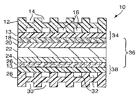
[0026] FIG. I is a cross-sectional view of a fuel cell having an anode
flow field plate, a
gas diffusion layer, an anode catalyst, a proton exchange membrane, a cathode
catalyst, a second
gas diffusion layer, and a cathode flow field plate.
[0027] FIG. 2 is a cross-sectional view of a membrane electrode assembly
for a fuel cell
having a sealant disposed at a peripheral portion of the assembly.
8
CA 02637061 2008-07-14
WO 2007/084472 PCT/US2007/001064
[00281 = FIG. 3 is a cross-sectional view of a membrane electrode assembly
for a fuel cell
having a sealant disposed at a peripheral portion and over the peripheral edge
portion of -the
assembly.
[0029] FIG. 4 is a cross-sectional view of a fuel cell having a sealant
disposed between
the membrane electrode assembly and the flow field plates of a fuel cell to
form a stacked fuel
cell assembly.
100301 FIG. 5 is a perspective view of a mold having a top and a bottom
mold member
for forming a gasket in accordance with the present invention.
[0031] FIG. 6 is a cross-sectional view of the mold of FIG. 5 taken along
the 6-6 axis.
[00321 FIG. 7 is an exploded view of the mold of FIG. 6 depicting the top
mold member
and the bottom mold member.
[00331 FIG. 8 is a bottom view of the top mold member of FIG. 7 taken
along the 8-8
axis.
[00341 FIG. 9 is a left elevational view of the top mold member of FIG. 8
taken along the
9-9 axis.
[0035] FIG. 10 is a right elevational view of the top mold member of FIG.
8 taken along
the 10-10 axis.
[00361 FIG. 11 a cross-sectional view of the top mold member of FIG. 8
taken along the
11-11 axis.
[00371 FIG. 12 is a perspective view of an alternative molds according to
the present
invention.
[00381 FIGS. 13A and 13B are cross-sectional views of the mold of FIG. 12
taken along
the 13-13 axis showing a fuel cell component disposed within the mold.
[0039] FIG. 14 is a perspective view of the top mold member of FIG. 5 or
12 depicting
the top mold member having transparent material.
9
CA 02637061 2008-07-14
WO 2007/084472 PCT/US2007/001064
100401 FIG. 15 is a cross-sectional view of the transparent top mold
member of FIG. 14
taken along the 15-15 axis.
DETAILED DESCRIPTION OF THE INVENTION:
[00411 The present invention is directed to a method for bonding and
compositions for
bonding components of an electrochemical cell. As used herein, an
electrochemical cell is a
device which produces electricity from chemical sources, including but not
limited to chemical
reactions and chemical combustion. Useful electrochemical cells include fuel
cells, dry cells,
wet cells and the like. A fuel cell, which is described in greater detail
below, produces electricity
from chemical reactants. A wet cell has a liquid electrolyte. A dry cell has
an electrolyte
absorbed in a porous medium or otherwise restrained from being flowable.
[00421 FIG. 1 shows a cross-sectional view of the basic elements of an
electrochemical
fuel cell, such as fuel cell 10. Electrochemical fuel cells convert fuel and
oxidant to electricity
and reaction product. Fuel cell 10 consists of an anode flow field plate 12
with open face coolant
channels 14 on one side and anode flow channels 16 on the second side, a resin
plate 13, a gas
diffusion layer 18, an anode catalyst 20, a proton exchange membrane 22, a
cathode catalyst 24,
a second gas diffusion layer 26, a second resin plate 13 and a cathode flow
field plate 28 with
open face coolant channels 30 on one side and cathode flow channels 32 on the
second side,
interrelated as shown in FIG. 1. The gas diffusion layer 18, the anode
catalyst 20, the proton
exchange membrane 22, the cathode catalyst 24 and the second gas diffusion
layer 26
combination is often referred to as a membrane electrode assembly 36. Gas
diffusion layers 18
and 26 are typically formed of porous, electrically conductive sheet material,
such as carbon
fiber paper. The present invention is not, however, limited to the use of
carbon fiber paper and
other materials may suitably be used. Fuel cells are not, however, limited to
such a depicted
arrangement of components. The anode and cathode catalyst layers 20 and 24 are
typically in
the form of finely comminuted platinum. The anode 34 and cathode 38 are
electrically coupled
(not shown) to provide a path for conducting electrons between the electrodes
to an external load
(not shown). The flow field plates 1.2 and 28 are typically formed of graphite
impregnated
plastic, compressed and exfoliated graphite; porous graphite; stainless steel
or other graphite
composites. The plates may be treated to effect surface properties, such as
surface wetting, or
CA 02637061 2008-07-14
WO 2007/084472 PCT/US2007/001064
may be untreated. The present invention is not, however, limited to the use of
such materials for
use as the flow field plates and other materials may suitably be used. For
example, in some fuel
cells the flow field plates are made from a metal or metal containing
material, typically, but not
limited to, stainless steel. The flow field plates may be bipolar plates,
i.e., a plate having flow
channels on opposed plate surfaces, as depicted in FIG. 1. Alternatively, the
bipolar plates may
be made by securing monopolar plates together.
[00431 Some fuel cell designs utilize resin frames 13 between the
membrane electrode
assembly 36 and the separator plates 12, 28 to improve the durability of the
membrane electrode
assembly 36 and afford the correct spacing between the membrane electrode
assembly 36 and
separator plates 12, 28 during fuel cell assembly. In such a design, it is
necessary have a seal
between the separator plates 12, 28 and the resin frames 13.
[00441 The present invention is not limited to the fuel cell components
and their
arrangement depicted in FIG. 1. For example, a direct methanol fuel cell
("DMFC") can consist
of the same components shown in FIG. 1 less the coolant channels. Further, the
fuel cell 10 can
be designed with internal or external manifolds (not shown).
[00451 While this invention has been described in terms of a proton
exchange membrane
(PEM) fuel cell, it should be appreciated that the invention is applicable to
any type of fuel cell.
The concepts in this invention can be applied to phosphoric acid fuel cells,
alkaline fuel cells,
higher temperature fuel cells such as solid oxide fuel cells and molten
carbonate fuel cells, and
other electrochemical devices.
100461 At anode 34, a fuel (not shown) traveling through the anode flow
channels 16
permeates the gas diffusion layer 18 and reacts at the anode catalyst layer 20
to form hydrogen
cations (protons), which migrate through the proton exchange membrane 22 to
cathode 38. The
proton exchange membrane 22 facilitates the migration of hydrogen ions from
the anode 34 to
the cathode 38. In addition to conducting hydrogen ions, the proton exchange
membrane 22
isolates the hydrogen-containing fuel stream from the oxygen-containing
oxidant stream.
[00471 At the cathode 38, oxygen-containing gas, such as air or
substantially pure
oxygen, reacts with the cations or hydrogen ions that have crossed the proton
exchange
11
CA 02637061 2008-07-14
WO 2007/084472 PCT/US2007/001064
membrane 22 to form liquid water as the reaction product. The anode and
cathode reactions in
hydrogen/oxygen fuel cells are shown in the following equations:
Anode reaction: I-12 2 H+ + 2 e-
(I)
Cathode reaction: 'A 02 + 2 H+ + 2 e- H20
(II)
[0048] FIG. 2 depicts the membrane electrode assembly 36 having a cured
or curable
composition 40 at or near the peripheral portion 33 of the membrane electrode
assembly 36_ As
described below, the composition 40 is useful for sealing ancUor bonding
different components of
the fuel cell to one and the other.
[0049] The present invention, however, is not limited to having fuel cell
components,
such as or the membrane electrode assembly 36, with the composition 40 at or
near the
peripheral portion 33 of the membrane electrode assembly 36. For example, as
depicted in FIG.
3, the curable or curable composition 40 may be disposed at or near the
peripheral portion 33 of
the membrane electrode assembly 36 and cover peripheral edge portions 35 of
the membrane
electrode assembly 36.
[0050] FIG. 4 shows a cross-sectional view of the basic elements of fuel
cell 10 in which
certain of the adjacent elements have a cured or curable composition 40
therebetween to provide
a fuel assembly 10'. As depicted in FIG. 4, composition 40 seals and/or bonds
the anode flow
field plate 12 to the gas diffusion layer 18 or the membrane electrode
assembly 36. The cathode
field plate 28 is also sealed and/or bonded to the gas diffusion layer 26 or
the membrane
electrode assembly 36. In this embodiment, fuel cell assembly 10' often has a
preformed
membrane electrode assembly 36 anode with the anode catalyst 20 and the
cathode catalyst 24
disposed thereon. The composition 40 disposed between the various components
of the fuel cell
assembly 10' may be the same composition or may be different compositions.
Additionally, as
depicted in FIG. 4, composition 40 may seal and/or bond the cathode flow plate
28 to a
component of a second fuel cell, such as a second anode flow field plate 12'.
Further, as
depicted in FIG. 4, composition 40 may seal and/or bond the second anode flow
field plate 12' to
a component of a second fuel cell, such as a second membrane electrode
assembly 36'. In such a
manner, the fuel cell assembly 10' is formed of multiple fuel cells having
components sealingly
and/or adhesively adjoined to provide a multiple cell electrochemical device.
12
CA 02637061 2008-07-14
WO 2007/084472 PCT/US2007/001064
100511 FIG. 5 is a perspective view of a mold 48 useful for forming cured-
in-place
gaskets according to the present invention. The mold 48 includes an upper mold
member 50, a
lower mold member 36', and an injection port 52, inter-related as shown. In
this embodiment,
composition 40 is disposed onto the lower mold member 36' to form a gasket
thereat or thereon.
In this embodiment of the present invention, the lower mold member 36' is
desirably a fuel cell
component, for example membrane electrode assembly 36. The present invention,
however, is
not limited to the use of the membrane electrode assembly 36 as the bottom
mold component,
and other fuel cell components may be the bottom mold component. As depicted
in FIG. 8, the
injection port 52 is in fluid communication with the mold cavity 54.
[00521 FIG. 6 is a cross-sectional view of the mold 48 of FIG. 5 taken
along the 6-6 axis.
As depicted in FIG. 6, the upper mold member 50 includes a mold cavity 54.
Liquid gasket-
forming compositions may be introduced into the mold cavity 54 via the
injection port 52.
[0053] FIG. 7 is a partial-break-away view of the mold 48 of FIG. 6. Mold
member 50
includes a mating surface 56, and mold member 36' includes a mating surface
58. The mold
members 50 and 36' may be aligned to one and the other, as depicted in FIG. 6,
such that the
mating surfaces 56 and 58 are substantially juxtaposed to one and the other.
As depicted in FIG.
7 a gasket 40 is removed from the mold cavity 54 and is attached to the mating
surface 58.
100541 As depicted in FIG. 8, the mold cavity 54 is in the shape of a
closed perimetric
design. Although mold cavity 54 is depicted as a rounded rectangle in FIG. 8,
the present
invention is not so limited and other shaped cavities may suitably be used.
Further, while the
cross-sectional shape of the mold cavity 54 is depicted as being rectangular
or square in FIG. 7,
the present invention is not so limited and other cross-sectional shapes may
suitably be used,
such as circular, oval, or shaped geometries having extensions for improved
sealing.
[00551 As depicted in FIG. 8, the mold 50 may contain a second port 60.
The second
port 60 is in fluid communication with the mold cavity 54. The second port 60
may be used to
degas the cavity 54 as it is being filled with the gasket-forming material. As
the gasket-forming
material in introduced into the cavity 54 via the port 52, air may escape via
the second port 60 to
degas the mold cavity 54. The size of the second port 60 is not limiting to
the present invention.
Desirably, the size, i.e., the cross-section extent, of the second port 60 is
minimized to allow for
13
CA 02637061 2008-07-14
WO 2007/084472 PCT/US2007/001064
the egress of air, but small enough to limit liquid flow of the gasket-forming
material
therethrough. In other words, the size of the second port 60 may be pin-hole
sized where air can
flow through while inhibiting substantial flow of liquid gasket-forming
material. Further, the
present invention is not limited to the use of a single port 52 or a single
port 60, and multiple
ports may be used for the introduction of the gasket material and/or the
venting of air.
[00561 FIG. 9 is a cross-sectional view of the mold member 50 taken along
the 9-9 axis
of FIG. 8. As depicted in FIG. 9, the injection port 52 may suitably be a
cavity or bore in the
mold member 50. The portion of the injection port 52 may be threaded (not
shown) or have a
valve (not shown) or a tubing or a hose (not shown) through which the gasket-
forming material
may be delivered.
[00571 FIG. 10 is a cross-sectional view of the mold member 50 taken
along the 10-10
axis of FIG. 8. As depicted in FIG. 10, the port 60 may suitably be a cavity
or bore in the mold
member 50. The portion of the port 60 may have a valve (not shown) for
controlling the egress
of air and/or gasket-forming material.
100581 FIG. 11 is a cross-sectional view of the mold member 50 taken
along the 1 1-1 1
axis of FIG. 8. The mold cavity 54 is depicted as extending into the mold
member 50 at its
mating surface 56.
[0059j FIG. 12 is a perspective view of a mold 48" useful for forming
cured-in-place
gaskets according to the present invention. The mold 48" includes an upper
mold member 50, a
lower mold member 70. As depicted in FIGS. 13A and 138, the mold members 50
and 70 are
fitable together in a fashion as discussed above and are configured such that
a fuel cell
component, such as membrane electrode assembly 36 may be disposed
therebetween. As
depicted in FIG. 13A, the mold 48" of the present invention may be used to
form the gasket 40
on peripheral portions of the opposed sides of the fuel cell component 36. As
depicted in FIG.
13B, the mold 48" of the present invention may also be used to form the gasket
40 on opposed
sides and over the peripheral sides of the fuel cell component 36.
[00601 FIG. 14 is a perspective view of the mold member 50, 70 depicting
that the mold
member 50, 70 may be made of or may comprise a transparent material.
Desirably, the mold
14
CA 02637061 2008-07-14
WO 2007/084472 PCT/US2007/001064
member 50, 70 is transparent, i.e., transmissible or substantially
transmissible, to actinic
radiation, for example ultraviolet (UV) radiation. A cross-sectional view of
the transparent mold
member 50, 70 is depicted in FIG. 15.
[0061] The method of this aspect of the present invention may further
include the step of
degassing the cavity prior to injecting or while injecting the liquid, actinic
radiation curable,
gasket-forming composition. Desirably, the step of degassing includes
degassing through the
second port 60, which is in fluid communication with the cavity 54.
[0062] With the degassing of the cavity 54 and with the above-described
fluid properties
the liquid composition fully fills the cavity 54 without the need for
excessive liquid handling
pressures. Desirably, the liquid composition fully fills the cavity 54 at a
fluid handling pressure
of about 690 kPa (100 psig) or less.
[0063] After the composition is cured or at least partially cured, the
mold members 50,
36' or 50, 70 may be released from one and the other to expose the gasket,
after which the gasket
40 may be removed from the mold cavity 54. The gasket 40 is desirably disposed
and/or affixed
to the fuel cell cornponent, for example membrane electrode assembly 36.
[0064] Although the present invention has been described as top mold
members 50, 70 as
having a groove or mold cavity 54, the present invention is not so limited.
For example, the
bottom mold member 36', 70 and/or the fuel cell component, such as membrane
exchange
membrane 36, may have a groove or mold cavity for placement and formation of
the seal in
addition to or in replacement to the mold cavity 54 of the top mold members.
[0065] Desirably, the liquid composition is cured at or about room
temperature within
about 5 minutes or less. More desirably, the liquid composition is cured
within 1 minute or less,
for example, cured within 30 seconds or less.
[0066] In another aspect of the present invention, a curable sealant may
be used in a
liquid injection molding process. The separator plates and resin frames may be
stacked and
aligned in the mold. The components are stacked from bottom to top in the
order of cathode
resin frame, cathode separator, anode separator, and anode resin frame, for
example. These fuel
cell components may contain one or more continuous pathways or gates that
allow the sealant to
CA 02637061 2008-07-14
WO 2007/084472 PCT/US2007/001064
pass through each component and bond the components while providing a molded
seal at the top,
bottom and/or on the edge. The sealant has a pumpable viscosity in its uncured
state to allow it
to assume the shape of the mold. The curable sealant is injected into the
heated mold, or die, at
an appropriate temperature to bond and seal fuel cell components.
[0067] In another aspect of the present invention, a curable sealant is
used in a liquid
injection molding process. The two separator plates are stacked and aligned in
the mold so that
the coolant pathway sides of the separators are facing each other. The
separators may contain
one or more continuous pathways that allow the sealant to bond each component
while providing
a molded seal at each end and/or on the edge. The sealant has a pumpable
viscosity in its
uncured state to allow it to assume the shape of the mold. The curable sealant
is injected into the
heated mold, or die, at the appropriate temperature to bond and seal the
separators. In the case
where there is no continuous pathway, an edge-sealed bipolar plate is
produced.
[0068] In another aspect of the present invention, a curable sealant is
used in a liquid
injection molding process. A fuel cell component such as a resin frame, which
may have one or
more gates or holes, is placed in a mold, or die. The sealant has a pumpable
viscosity in its
uncured state to allow it to assume the shape of the mold. The sealant is
injected into the heated
mold, or die, at the appropriate temperature to cure the sealant. A resin
frame with integrated
seals on both sides, and possibly the edge, is provided.
[0069] It is also envisioned that selected components may be bonded in
another process,
then proceed to the method described in this invention to be bonded and
sealed. As an example,
an MEA and a bonded assembly are stacked and aligned in a molding process. The
bonded
assembly may be composed of the resin frames and separators, as an example.
The MEA and
the bonded assembly may contain one or more continuous pathways that allow the
sealant to
bond each component while providing a molded seal at each end and/or on the
edge. The sealant
has a pumpable viscosity in its uncured state to allow it to assume the shape
of the mold. The
curable sealant is injected into the heated mold, or die, at the appropriate
temperature to bond
and seal the separators.
[0070] In one aspect of the present invention, the cured sealant
composition used in the
present invention includes an alkenyl terminated polyisobutylene oligomer, for
example an
16
CA 02637061 2008-07-14
WO 2007/084472 PCT/US2007/001064
alkenyl terminated diallyl polyisobutylene oligomer; optionally, a
polyfunctional alkenyl
monomer; a silyl hardener or cross-linker having at least one hydrogen atom
bonded to a silicon
atom; and a hydrosilyIation catalyst. Desirably, only about one hydrogen atom
bonded is to any
silicon atom in the silyl hardener.
[0071] The inventive compositions of the present invention have modified
molecular
structures, resulting in enhanced mechanical properties, cross-link densities
and heats of reaction.
The compositions of the present invention may be represented by the expression
of (A-A + Af +
Bf), where "A-A" represents the alkenyl groups of the alkenyl terminated
diallyl polyisobutylene
oligomer, i.e., a difunctional alkenyl polyisobutylene ("PIB"), "A" represents
an alkenyl group,
"B" represents a Si-H group and "f" refers to the number of corresponding
functional groups.
[0072] When both the alkenyl and hydride are di-functional, the
polymerization yields a
linear structure. The number of functional hydride groups in such a linear
structure, however,
limits the overall functionality and cross-linked density of the reacted
network. By incorporating
three or more alkenyl groups onto a single monomer or oligomer the cross-
linking density
increases and mechanical properties are improved.
[0073] Useful dialkenyl terminated linear poly(isobutylene) oligomers are
commercially
available from Kaneka Corporation, Osaka, Japan as EP200A, EP400A and EP600A.
The three
oligomers have the same functionality and have different molecular weights.
EP200A, EP400A
and EP600A have an approximate molecular weight (Mn) of 5,000, 10,000, and
20,000,
respectively.
[0074] The compositions of the present invention may also include a
silicone having at
least two reactive silicon hydride functional groups, i.e., at least two Si-H
groups. This
component functions as a hardener or cross-linker for the alkenyl terminated
diallyl
polyisobutylene oligomer. In the presence of the hydrosilation catalyst, the
silicon-bonded
hydrogen atoms in the cross-linking component undergo an addition reaction,
which is referred
to as hydrosilation, with the unsaturated groups in the reactive oligomer.
Since the reactive
oligomer contains at least two unsaturated groups, the silicone cross-linking
component may
desirably contain at least two silicon-bonded hydrogen atoms to achieve the
final= cross-linked
structure in the cured product. The silicon-bonded organic groups present in
the silicone cross-
17
CA 02637061 2013-02-14
linking component may be selected from the same group of substituted and
unsubstituted
monovalent hydrocarbon radicals as set forth above for the reactive silicone
component, with the
exception that the organic groups in the silicone cross-linker should be
substantially free of
ethylenic or acetylenic unsaturation. The silicone cross-linker may have a
molecular structure
that can be straight chained, branched straight chained, cyclic or networked.
[0075] The silicone cross-linking component may be selected from a wide
variety of
compounds, that desirably conforms to the formula below:
R4
R4
R4
R4
1
R ___________________ Si __ 0--(Si 0)---(Si 0) ___ Si __ R2
I 4 I 4 X Y
R4
where at least two of R', R2 and R3 are H; otherwise RI, R2 and R3 can be the
same or different
and can be a substituted or unsubstituted hydrocarbon radical from C1-20 such
hydrocarbon
radicals including alkyl, alkenyl, aryl, alkoxy, alkenyloxy, aryloxy,
(meth)acryl or
(meth)acryloxy; thus the SiH group may be terminal, pendent or both; R4 can
also be a
substituted or unsubstituted hydrocarbon radical from C1-20, such hydrocarbon
radicals including
a C1-20 alkyl, alkenyl, aryl, alkoxy, alkenyloxy, aryloxy, (meth)acryl or
(meth)acryloxy, and
desirably is an alkyl group such as methyl; x is an integer from 10 to 1,000;
and y is an integer
from 1 to 20. Desirably, R2 and R3 are not both hydrogen, i.e., R1 is H and
either R2 or R3, but
not both, is H. Desirably, R groups which are not H are methyl. The silicon
hydride crosslinker
should be present in amounts sufficient to achieve the desired amount of
crosslinking and
desirably in amounts of about 0.5 to about 40 percent by weight of the
composition, more
desirably from about 1 to about 20 percent by weight of the composition.
[0076] Useful platinum catalysts include platinum or platinum-containing
complexes such as the platinum hydrocarbon complexes described in U.S. Patent
Nos. 3,159,601 and 3,159,662; the platinum alcoholate catalysts described in
U.S. Patent
No. 3,220,972; the platinum complexes described in U.S. Patent No. 3,814,730;
and the
platinum chloride-olefin complexes described in U.S. Patent No. 3,516,946.
Desirably,
the platinum or platinum-containing complex is dicarbonyl platinum cyclovinyl
complex,
platinum cyclovinyl complex, platinum divinyl complex, or combinations
thereof. The
18
CA 02637061 2013-02-14
=
platinum catalysts are in sufficient quantity such that the composition cures
at a temperature of
about 130 C or less, desirably at a temperature of about 100 C or less, more
desirably at a
temperature of about 90 C or less.
100771 In another aspect of the present invention, the liquid
gasket-forming material may
include actinic radiation curable acrylates, urethanes, polyethers,
polyolefins, polyesters,
copolymers thereof and combinations thereof Desirably, the curable material
includes a
(meth)acryloyl terminated material having at least two (meth)acryloyl pendant
groups.
Desirably, the (meth)acryloyl pendant group is represented by the general
formula:
¨0C(0)C(R1)=CH2, where R1 is hydrogen or methyl. More desirably, the liquid
gasket-forming
material is a (meth)acryloyl-terminated poly acrylate. The (meth)acryloyl-
terminated poly
acrylate may desirably have a molecular weight from about 3,000 to about
40,000, more
desirably from about 8,000 to about 15,000. Further, the (meth)acryloyl-
terminated poly acrylate
may desirably have a viscosity from about 200 Pas (200,000 cPs) to about 800
Pas (800,000 cPs)
at 25 C (77 F), more desirably from about 450 Pas (450,000 cPs) to about 500
Pas (500,000
cPs). Details of such curable (meth)acryloyl-terminated materials may be found
in European
Patent Application No. EP 1 059 308 Al to Nakagawa et al., and are
commercially available
from Kaneka Corporation, Japan.
100781 Desirably, the liquid composition includes a photoinitiator.
A number of
photoinitiators may be employed herein to provide the benefits and advantages
of the present
invention to which reference is made above. Photoinitiators enhance the
rapidity of the curing
process when the photocurable compositions as a whole are exposed to
electromagnetic
radiation, such as actinic radiation. Examples of suitable photoinitiators for
use herein include,
but are not limited to, photoinitiators available commercially from Ciba
Specialty Chemicals,
under the "IRGACURE" and "DAROCUR" trade marks, specifically "IRGACURE" 184
(1-hydroxycyclohexyl phenyl ketone), 907 (2-methyl-144-(methylthio)pheny1]-2-
morpholino
propan-l-one), 369 (2-benzy1-2-N,N-dimethylamino-1-(4-morpholinopheny1)-1-
butanone), 500
(the combination of 1-hydroxy cyclohexyl phenyl ketone and benzophenone), 651
(2,2-
dimethoxy-2-phenyl acetophenone), 1700 (the combination of bis(2,6-
dimethoxybenzoy1-2,4,4-
trimethyl pentyl) phosphine oxide and 2-hydroxy-2-methyl-1-phenyl-propan-1-
one), and 819
[bis(2,4,6-trimethyl benzoyl) phenyl phosphine oxide] and "DAROCUR" 1173 (2-
hydroxy-2-
19
CA 02637061 2008-07-14
WO 2007/084472 PCT/US2007/001064
inethyl-.1-pheny1-1-propan-1-one) and 4265 (the combination of 2,4,6-
trimethylbenzoyldiphenyl-
phosphine oxide and 2-hydroxy-2-methyl-1-phenyl-propan-1-one); and the visible
light [blue]
photoinitiators, dl-camphorquinone and "IRGACURE" 784DC. Of course,
combinations of
these materials may also be employed herein.
[0079] Other photoinitiators useful herein include alkyl pyruvates, such
as methyl, ethyl,
propyl, and butyl pyruvates, and aryl pyruvates, such as phenyl, benzyl, and
appropriately
substituted derivatives thereof. Photoinitiators particularly well-suited for
use herein include
ultraviolet photoinitiators, such as 2,2-dimethoxy-2-phenyl acetophenone
(e.g., "IRGACURE"
651), and 2-hydroxy-2-methyl-1-pheny1-1-propane (e.g., "DAROCUR" 1173),
bis(2,4,6-
trimethyl benzoyl) phenyl phosphine oxide (e.g., "IRGACURE" 819), and the
ultraviolet/visible
photoinitiator combination of bis(2,6-dimethoxybenzoy1-2,4,4-trimethylpentyl)
phosphine oxide
and 2-hydroxy-2-methyl-1-phenyl-propan-1-one (e.g., "IRGACURE" 1700), as well
as the
visible photoinitiator bis (r5-2,4-cyclopentadien-1-y1)-bis[2,6-difluoro-3-(11-
1-pyrrol-1-
yOphenylititanium (e.g., "IRGACURE" 784DC). Useful actinic radiation includes
ultraviolet
light, visible light, and combinations thereof. Desirably, the actinic
radiation used to cure the
liquid gasket-forming material has a wavelength from about 200 nm to about
1,000 nm. Useful
UV includes, but is not limited to, UVA (about 320 nm to about 410 nm), UVB
(about 290 nm to
about 320 nm), UVC (about 220 nm to about 290 nm) and combinations thereof.
Useful visible
light includes, but is not limited to, blue light, green light, and
combinations thereof_ Such useful
visible lights have a wavelength from about 450 nm to about 550 nm.
[0080] Optionally, a release agent may be applied to the cavity 54 prior
to the
introduction of the liquid composition. The release agent, if needed, helps in
the easy removal of
the cured gasket from the mold cavity. Useful mold release compositions
include, but are not
limited, to dry sprays such as polytetrafluoroethylene, and spray- on-oils or
wipe-on-oils such as
silicone or organic oils. Useful mold release compositions include, but are
not limited, to
compositions including C6 to Ct4 perfluoroalkyl compounds terminally
substituted on at least one
end with an organic hydrophilic group, such as betaine, hydroxyl, carboxyl,
ammonium salt
groups and combinations thereof, which is chemically and/or physically
reactive with a metal
surface. A variety of mold releases are available, such as those marketed
under Henkel's Frekote
CA 02637061 2008-07-14
WO 2007/084472 PCT/US2007/001064
brand. Additionally, the release agent may be a thermoplastic film, which can
be formed in the
= mold shape.
21