Language selection

Search

Patent 2637291 Summary

Third-party information liability

Some of the information on this Web page has been provided by external sources. The Government of Canada is not responsible for the accuracy, reliability or currency of the information supplied by external sources. Users wishing to rely upon this information should consult directly with the source of the information. Content provided by external sources is not subject to official languages, privacy and accessibility requirements.

Claims and Abstract availability

Any discrepancies in the text and image of the Claims and Abstract are due to differing posting times. Text of the Claims and Abstract are posted:

  • At the time the application is open to public inspection;
  • At the time of issue of the patent (grant).
(12) Patent Application: (11) CA 2637291
(54) English Title: GUIDE BLADE SEGMENT OF A GAS TURBINE AND METHOD FOR ITS PRODUCTION
(54) French Title: SEGMENT D'AUBE DE GUIDAGE D'UNE TURBINE A GAZ ET PROCEDE POUR SA FABRICATION
Status: Deemed Abandoned and Beyond the Period of Reinstatement - Pending Response to Notice of Disregarded Communication
Bibliographic Data
(51) International Patent Classification (IPC):
  • F01D 11/00 (2006.01)
(72) Inventors :
  • MEIER, REINHOLD (Germany)
  • MUELLER, CLAUS (Germany)
  • DUSEL, KARL-HEINZ (Germany)
  • HUTTNER, ROLAND (Germany)
(73) Owners :
  • MTU AERO ENGINES GMBH
(71) Applicants :
  • MTU AERO ENGINES GMBH (Germany)
(74) Agent: MARKS & CLERK
(74) Associate agent:
(45) Issued:
(86) PCT Filing Date: 2007-01-19
(87) Open to Public Inspection: 2007-08-02
Examination requested: 2012-01-18
Availability of licence: N/A
Dedicated to the Public: N/A
(25) Language of filing: English

Patent Cooperation Treaty (PCT): Yes
(86) PCT Filing Number: PCT/DE2007/000097
(87) International Publication Number: DE2007000097
(85) National Entry: 2008-07-16

(30) Application Priority Data:
Application No. Country/Territory Date
10 2006 004 090.2 (Germany) 2006-01-28

Abstracts

English Abstract


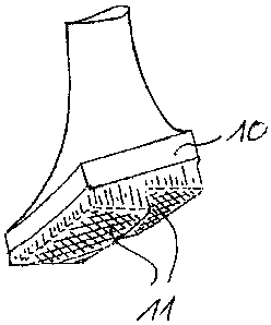
The invention relates to a guide blade segment of a gas turbine, having at
least one guide blade and having an inner cover band (10) assigned to the
radially inner end of the or each guide blade. According to the invention, an
integral constituent part of the inner cover band (10) of the guide blade
segment is a sealing element (11) which serves to seal a radially inner gap
between the guide blade segment and a gas turbine rotor.


French Abstract

L'invention concerne un segment d'aube de guidage pour turbine à gaz, qui présente au moins une aube de guidage et une bande intérieure de recouvrement (10) associée à l'extrémité située radialement à l'intérieur de la ou des aubes de guidage. Selon l'invention, un élément d'étanchéité (11) qui assure l'étanchéité d'un interstice radial intérieur entre le segment d'aube de guidage et le rotor de la turbine à gaz fait partie intégrante de la bande intérieure de recouvrement (10) du segment d'aube de guidage.

Claims

Note: Claims are shown in the official language in which they were submitted.


Claims
1. Guide blade segment of a gas turbine, having at least one guide blade and
having an inner
cover band assigned to the radially inner end of the or each guide blade,
characterized in that
an integral constituent part of the inner cover band (10) of the guide blade
segment is a
sealing element (11), which serves to seal a radially inner gap between the
guide blade
segment and a gas turbine rotor.
2. Guide blade segment according to Claim 1,
characterized in that
the sealing element (11) is integrally cast on the inner cover band (10).
3. Guide blade segment according to Claim 1,
characterized in that
the sealing element (11) is integrally formed on the inner cover band (10)
using injection
molding.
4. Guide blade segment according to one or more of Claims 1 through 3,
characterized in that
the sealing element (11) is a honeycomb seal.
5. Method for producing a guide blade segment of a gas turbine, wherein the
guide blade
segment has at least one guide blade and an inner cover band assigned to the
radially
inner end of the or each guide blade,
characterized in that
a sealing element, which serves to seal a radially inner gap between the guide
blade
segment and a gas turbine rotor, is formed on the inner cover band of the
guide blade
segment as an integral constituent part of same.
6. Method according to Claim 5,
characterized in that
the sealing element is integrally cast on the inner cover band.
6

7. Method according to Claim 5,
characterized in that
the sealing element is integrally formed on the inner cover band using
injection molding.
8. Method according to Claim 7,
characterized in that,
for this purpose, a common molded article or green compact is produced during
injection
molding for the sealing element and the inner cover band.
9. Method according to Claim 7,
characterized in that,
for this purpose, separate molded articles or green compacts are produced
during
injection molding for the sealing element and the inner cover band, which as
brown
compacts are formed on one another and jointly sintered.
10. Method according to one or more of Claims 5 through 9,
characterized in that
the injection molding is carried out as two-component injection molding.
11. Method according to one or more of Claims 5 through 10,
characterized in that
a homogeneous mass made of a powder, binding agent, and plasticizing agent is
used
during injection molding, wherein a hard metal powder and/or a powder of an
intermetallic phase and/or a powder of metal alloys and/or a ceramic powder is
used as
the powder.
12. Method according to Claim 5, characterized in that the sealing element and
the inner
cover band are integrally formed by generative manufacturing methods, in
particular the
rapid prototyping method.
13. Method according to Claim 12, characterized in that laser engineered net
shaping,
electron-beam melting, laser sintering, laser melting, laser shaping, or laser
powder
application welding are used.
7

Description

Note: Descriptions are shown in the official language in which they were submitted.


CA 02637291 2008-07-16
Guide Blade Segment of a Gas Turbine and Method for its Production
The invention relates to a guide blade segment of a gas turbine according to
the pre-
characterizing clause of Claim 1. In addition, the invention relates to a
method for producing a
guide blade segment of a gas turbine according to the pre-characterizing
clause of Claim 5.
Gas turbines, particularly gas turbine aircraft engines, have stationary guide
blade rings and
rotating rotor blade rings in the region of their compressors and turbines,
wherein the stationary
guide blade rings are assigned to a stationary housing and the rotating rotor
blade rings to a
rotating rotor of the gas turbine. The stationary guide blade rings are formed
by several guide
blade segments, wherein each guide blade segment includes at least one guide
blade. Assigned
to the radially inner end of the or each guide blade of a guide blade segment
is an inner cover
band, wherein, in order to guarantee an optimal degree of efficiency of a gas
turbine, a radially
inner gap between the inner cover band of the guide blades and the rotor of
the gas turbine needs
to be sealed. Sealing the radial inner gap between the inner cover band and
the rotor of the gas
turbine is accomplished using what is commonly called an inner air seal,
wherein, for this
purpose, sealing elements are assigned to the inner band of the guide blade
segments. These
sealing elements can be designed as honeycomb seals.
In the case of guide blade segments known from practice, the sealing elements
are designed as
separate components and are permanently connected to the inner cover band of
the guide blade
segments by soldering for example. The result of this is a high manufacturing
effort, since, on
the one hand, the sealing elements must be manufactured as a separate
component using separate
manufacturing methods, and since, on the other hand, the sealing elements have
to be connected
to the inner cover band using a joining method. Furthermore, soldered
connections for the most
part represent thermo-mechanical weak points.
Starting herefrom, the present invention is based on the objective of creating
a novel guide blade
segment of a gas turbine and a method for producing same. This objective is
attained by a guide
blade segment within the scope of Claim 1. According to the invention, an
integral constituent
part of the inner cover band of the guide blade segment is a sealing element,
which serves to seal
a radially inner gap between the guide blade segment and a gas turbine rotor.
1

CA 02637291 2008-07-16
In terms of the present invention, it is proposed in the case of a guide blade
segment of a gas
turbine, that the sealing element be designed as an integral constituent part
of the inner cover
band of the guide blade segment. This is preferably accomplished in that the
sealing element and
the inner cover band of the guide blade segment are manufactured integrally in
a forming
process. Manufacturing costs can be reduced due to the integral design of the
sealing element
with the inner cover band of the guide blade segment, because, on the one
hand, a separate
manufacturing process for the sealing element and, on the other hand, a
joining of the sealing
element to the inner cover band of the guide blade segment are eliminated. By
eliminating
joined connections between the sealing element and the inner cover band of the
guide blade
segment, the service life of the guide blade segments can also be increased,
because the joined
connections or joined points that are required by the prior art between the
sealing element and
the inner cover band of the guide blade segment represent weak points. In
particular, eliminating
the soldering heat treatment that is customary in the case of compressor guide
blade segments
does not reduce the fatigue strength of the guide blade segments.
The inventive method for manufacturing a guide blade segment of a gas turbine
is defined in
Claim 5.
Preferred developments of the invention are disclosed in the subordinate
claims and the
subsequent description. Without being limited hereto, exemplary embodiments of
the invention
are explained in greater detail on the basis of the drawing. The drawing
shows:
Fig. 1 a schematic section of an inventive guide blade segment of a gas
turbine in the region
of an inner cover band of the guide blade segment; and
Fig. 2 a detail of the inner cover band from Fig. I in the region of a sealing
element
embodied as an integral constituent part of the inner cover band.
Fig. I shows a section of an inventive guide blade segment of a gas turbine in
the region of an
inner cover band 10 arranged on radially inner ends of guide blades of the
guide blade segment,
wherein a sealing element 11 is assigned to the inner cover band 10 in the
exemplary
embodiment in Fig. 1. The sealing element 11 serves to seal a radially inner
gap between the
guide blade segment and a gas turbine rotor.
2

CA 02637291 2008-07-16
In terms of the present invention, the sealing element 11 is an integral
constituent part of the
inner cover band 10 of the guide blade segment. The sealing element 11 in this
case is either
integrally cast on the inner cover band 10 of the guide blade segment or
integrally formed on the
inner cover band 10 using powder metallurgical injection molding. The sealing
element
according to Fig. 2 is preferably embodied as a honeycomb seal made of several
honeycombs 12,
wherein the honeycombs 12 can have any contour. Thus, Fig. 2 exemplarily shows
honeycombs
12, which have a round contour in cross section, as well as honeycombs 12,
which have a
hexagonal or honeycombed contour in cross section.
As already stated above, the inventive guide blade segment is preferably
manufactured in that the
sealing element is either integrally cast on the inner cover band, integrally
formed on the inner
cover band using powder metallurgical injection molding, or the sealing
element and the inner
cover band are integrally manufactured using generative manufacturing methods.
If the manufacturing variant of powder metallurgical injection molding, which
is also known as
the metal injection molding (MIM) method, is selected, the preferred procedure
is that a common
molded article is manufactured by injection molding for the inner cover band
and thus the guide
blade segment as well as the sealing element, wherein the molded article is
also designated as a
green compact. In this case, the sealing element is then already an integral
constituent part of the
inner cover band in the green compact, wherein subsequently, as is customary
in powder
metallurgical injection molding, a binding agent and plasticizing agent are
expelled from the
green compact to produce a brown compact. The brown compact is then sintered
in order to
make the guide blade segment available.
Alternatively, it is also possible to manufacture separate green compacts for
the inner cover band
or the guide blade segment and the sealing element, wherein brown compacts are
manufactured
from these green compacts by expelling the binding agent and plasticizing
agent, and said brown
compacts are then formed on one another and jointly sintered.
A further alternative for powder metallurgical injection molding can be seen
in first
manufacturing a green compact for the inner cover band or guide blade segment
and converting
this green compact into a brown compact by expelling the binding agent and
plasticizing agent,
wherein the sealing element is then integrally formed on this brown compact by
injection
molding.
3

CA 02637291 2008-07-16
In powder metallurgical injection molding, the composition of a homogeneous
mass made of
metal powder, binding agent, and plasticizing agent that is used for injection
molding can be
adapted. Thus, when a common molded article or green compact is manufactured
by injection
molding for the inner cover band and the sealing element, during injection
molding, the
composition of the homogenous mass used for injection molding can be modified
in order to
thereby guarantee different properties in the region of the sealing element
than in the rest of the
guide blade segment.
Instead of the one-component injection molding, a two-component injection
molding can also be
carried out, wherein a first homogenous mass is then used for the injection
molding of the guide
blade segment, and a second homogeneous mass is used for the injection molding
of the sealing
element, and these two homogenous masses differ in terms of their
compositions. The
compositions are adapted respectively to the required properties of the guide
blade segment and
sealing element.
A hard metal powder and/or a powder of intermetallic phases, such as, e.g.,
titanium aluminide,
and/or a powder of metal alloys can be used as the metal powder in the
respective, homogeneous
mass required for injection molding. In addition or as an alternative to the
metal powder, a
ceramic powder can also be used as the homogeneous mass required for injection
molding.
In the case of the alternative manufacturing route using generative
manufacturing methods, the
sealing element and the inner cover band are built up in layers integrally,
i.e., made of one piece,
in particular using rapid prototyping methods. Used preferably as the
generative manufacturing
method is laser engineered net shaping, which uses electron-beam melting,
laser sintering, laser
melting, laser shaping, or laser powder application welding. Cobalt, nickel,
iron, or even
titanium-based alloys can be used for this, in that as sinterable powders,
these materials are built
up in layers by means of a source of radiation in a natural or artificial
environment directly from
the component's CAD data.
Due to this layered structure, solid and even hollow structures can be
manufactured in a manner
that is satisfactory in terms of load. The sealing element can consequently be
structured in a
simple manner as a hollow space that is open on one side (e.g., honeycombs),
as a metallic grid
structure, or a foam structure.
4

CA 02637291 2008-07-16
Following the different manufacturing routes, finish machining for the final
contour can also still
be performed by removal methods such as milling, lathing, eroding, or
electrochemical
processing.
***

Representative Drawing
A single figure which represents the drawing illustrating the invention.
Administrative Status

2024-08-01:As part of the Next Generation Patents (NGP) transition, the Canadian Patents Database (CPD) now contains a more detailed Event History, which replicates the Event Log of our new back-office solution.

Please note that "Inactive:" events refers to events no longer in use in our new back-office solution.

For a clearer understanding of the status of the application/patent presented on this page, the site Disclaimer , as well as the definitions for Patent , Event History , Maintenance Fee  and Payment History  should be consulted.

Event History

Description Date
Application Not Reinstated by Deadline 2014-01-21
Time Limit for Reversal Expired 2014-01-21
Deemed Abandoned - Failure to Respond to Maintenance Fee Notice 2013-01-21
Letter Sent 2012-02-01
Request for Examination Requirements Determined Compliant 2012-01-18
All Requirements for Examination Determined Compliant 2012-01-18
Request for Examination Received 2012-01-18
Inactive: Office letter 2011-03-23
Inactive: Office letter 2009-02-02
Letter Sent 2009-02-02
Inactive: Single transfer 2008-12-12
Correct Applicant Request Received 2008-11-10
Inactive: Cover page published 2008-11-06
Inactive: Notice - National entry - No RFE 2008-10-22
Inactive: First IPC assigned 2008-09-05
Application Received - PCT 2008-09-04
National Entry Requirements Determined Compliant 2008-07-16
Application Published (Open to Public Inspection) 2007-08-02

Abandonment History

Abandonment Date Reason Reinstatement Date
2013-01-21

Maintenance Fee

The last payment was received on 2012-01-18

Note : If the full payment has not been received on or before the date indicated, a further fee may be required which may be one of the following

  • the reinstatement fee;
  • the late payment fee; or
  • additional fee to reverse deemed expiry.

Patent fees are adjusted on the 1st of January every year. The amounts above are the current amounts if received by December 31 of the current year.
Please refer to the CIPO Patent Fees web page to see all current fee amounts.

Fee History

Fee Type Anniversary Year Due Date Paid Date
Basic national fee - standard 2008-07-16
MF (application, 2nd anniv.) - standard 02 2009-01-19 2008-07-16
Registration of a document 2008-12-12
MF (application, 3rd anniv.) - standard 03 2010-01-19 2009-12-22
MF (application, 4th anniv.) - standard 04 2011-01-19 2010-12-29
Request for examination - standard 2012-01-18
MF (application, 5th anniv.) - standard 05 2012-01-19 2012-01-18
Owners on Record

Note: Records showing the ownership history in alphabetical order.

Current Owners on Record
MTU AERO ENGINES GMBH
Past Owners on Record
CLAUS MUELLER
KARL-HEINZ DUSEL
REINHOLD MEIER
ROLAND HUTTNER
Past Owners that do not appear in the "Owners on Record" listing will appear in other documentation within the application.
Documents

To view selected files, please enter reCAPTCHA code :


To view images, click a link in the Document Description column. To download the documents, select one or more checkboxes in the first column and then click the "Download Selected in PDF format (Zip Archive)" or the "Download Selected as Single PDF" button.

List of published and non-published patent-specific documents on the CPD .

If you have any difficulty accessing content, you can call the Client Service Centre at 1-866-997-1936 or send them an e-mail at CIPO Client Service Centre.


Document
Description 
Date
(yyyy-mm-dd) 
Number of pages   Size of Image (KB) 
Abstract 2008-07-15 1 11
Description 2008-07-15 5 238
Drawings 2008-07-15 1 18
Claims 2008-07-15 2 70
Representative drawing 2008-10-22 1 8
Notice of National Entry 2008-10-21 1 208
Courtesy - Certificate of registration (related document(s)) 2009-02-01 1 104
Reminder - Request for Examination 2011-09-19 1 117
Acknowledgement of Request for Examination 2012-01-31 1 189
Courtesy - Abandonment Letter (Maintenance Fee) 2013-03-17 1 173
PCT 2008-07-15 4 150
Correspondence 2008-11-09 1 35
Correspondence 2009-02-01 1 9
Correspondence 2011-03-22 1 14