Language selection

Search

Patent 2637497 Summary

Third-party information liability

Some of the information on this Web page has been provided by external sources. The Government of Canada is not responsible for the accuracy, reliability or currency of the information supplied by external sources. Users wishing to rely upon this information should consult directly with the source of the information. Content provided by external sources is not subject to official languages, privacy and accessibility requirements.

Claims and Abstract availability

Any discrepancies in the text and image of the Claims and Abstract are due to differing posting times. Text of the Claims and Abstract are posted:

  • At the time the application is open to public inspection;
  • At the time of issue of the patent (grant).
(12) Patent Application: (11) CA 2637497
(54) English Title: LIQUID LEVEL AND DENSITY MEASUREMENT DEVICE
(54) French Title: DISPOSITIF DE MESURE DU NIVEAU ET DE LA DENSITE D'UN LIQUIDE
Status: Deemed Abandoned and Beyond the Period of Reinstatement - Pending Response to Notice of Disregarded Communication
Bibliographic Data
(51) International Patent Classification (IPC):
  • G01F 23/38 (2006.01)
  • G01F 23/76 (2006.01)
(72) Inventors :
  • DEMIN, VITALIY (United States of America)
(73) Owners :
  • FRANKLIN FUELING SYSTEMS, INC.
(71) Applicants :
  • FRANKLIN FUELING SYSTEMS, INC. (United States of America)
(74) Agent: SMART & BIGGAR LP
(74) Associate agent:
(45) Issued:
(86) PCT Filing Date: 2006-01-30
(87) Open to Public Inspection: 2007-08-02
Examination requested: 2010-11-05
Availability of licence: N/A
Dedicated to the Public: N/A
(25) Language of filing: English

Patent Cooperation Treaty (PCT): Yes
(86) PCT Filing Number: PCT/US2006/003236
(87) International Publication Number: US2006003236
(85) National Entry: 2008-07-17

(30) Application Priority Data: None

Abstracts

English Abstract


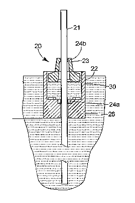
A liquid level and density measurement device is disclosed. The device
comprises an elongated magnetostrictive transducer and at least two transducer
magnets embedded into floats that can freely move along a transducer. One
float is relatively more sensitive to liquid density variation than the other
float. The less sensitive float is used for liquid level measurement and the
more sensitive float is used for liquid density measurement. The liquid
density float has a lower part completely immersed into a liquid and an upper
part partially immersed into a liquid. The upper part is made substantially in
the form of a hollow cylinder with an internal diameter larger than the
external diameter of the liquid level float. Therefore the liquid density
float can move up and down without touching the liquid level float.


French Abstract

L~invention concerne un dispositif de mesure du niveau et de la densité d~un liquide. Le dispositif comprend un transducteur magnétostrictif allongé et au moins deux aimants de transducteur incorporés dans des flotteurs susceptibles de se déplacer librement le long du transducteur. Un flotteur est relativement plus sensible que l~autre à une variation de densité du liquide. Le flotteur moins sensible est utilisé pour mesurer le niveau du liquide et le flotteur plus sensible est utilisé pour mesurer la densité du liquide. Le flotteur utilisé pour mesurer la densité du liquide comporte une partie inférieure complètement immergée dans le liquide et une partie supérieure partiellement immergée dans le liquide. La partie supérieure prend sensiblement la forme d~un cylindre creux dont le diamètre intérieur est supérieur au diamètre extérieur du flotteur utilisé pour mesurer le niveau du liquide. Le flotteur utilisé pour mesurer la densité du liquide peut donc monter et descendre sans entrer au contact du flotteur utilisé pour mesurer le niveau du liquide.

Claims

Note: Claims are shown in the official language in which they were submitted.


CLAIM:
1. A device for placement in a tank of liquid for determining the level and
density of the liquid in the tank, the device comprising:
a liquid density sensing float having a lower base portion and an upper
portion
extending substantially continuously about a periphery of the base portion and
defining a
cavity;
a liquid level sensing float disposed in the cavity; and
circuitry for determining the height of the density sensing float and the
level
sensing float.
2. The device of claim 1 wherein the density sensing float and the level
sensing
float include a magnet and the circuitry includes a magnetostrictive
transducer.
3. The device of claim 2 wherein the density sensing float and the level
sensing
float include an aperture to slidably receive the magnetostrictive transducer.
4. The device of claim 1 wherein the density sensing float is dimensioned to
fit
through a four inch opening into the tank.
5. The device of claim 1 wherein the upper portion is substantially
cylindrical.
6. A device for placement in an underground liquid storage tank, the device to
determine the level and density of liquid in the tank, the device comprising:
a magnetostrictive transducer to be generally vertically disposed in the tank;
a liquid density sensing float having a lower base portion and a generally
cylindrical upper portion extending substantially continuously about a
periphery of the base
portion and defining a cavity, wherein the density sensing float includes a
magnet and the
base portion has a bore to slidably receive the transducer;
a liquid level sensing float slidably disposed in the cavity and having a bore
to
slidably receive the transducer, wherein the level sensing float includes a
magnet; and
circuitry coupled to the transducer for determining the position of the
magnets
relative to the transducer.

7. A system for measuring the height and density of a liquid comprising:
an underground storage tank containing the liquid and having a nominally four
inch opening;
a magnetostrictive transducer generally vertically disposed in the tank;
a liquid density sensing float having a lower base portion and a generally
cylindrical upper portion extending substantially continuously about a
periphery of the base
portion and defining a cavity, wherein the density sensing float includes a
magnet and the
base portion has a bore slidably receiving the transducer;
a liquid level sensing float slidably disposed in the cavity and having a bore
slidably receiving the transducer, wherein the level sensing float includes a
magnet; and
circuitry coupled to the transducer for determining the position of the
magnets
relative to the transducer.
8. A liquid level and density measurement device comprising an elongated
magnetostrictive transducer and at least two transducer magnets embedded into
a liquid
density float and a liquid level float and spaced along a transducer, wherein
the liquid density
float is more sensitive to liquid density variations than the liquid level
float, and the liquid
density float has a lower part completely immersed into a liquid wherein the
improvement
comprises:
an upper part of the liquid density float partially immersed into the liquid
is
made substantially in the form of hollow cylinder with an internal diameter
larger than the
external diameter of the liquid level float.
6

Description

Note: Descriptions are shown in the official language in which they were submitted.


CA 02637497 2008-07-17
WO 2007/086873 PCT/US2006/003236
LIQUID LEVEL AND DENSITY MEASUREMENT DEVICE
THE FIELD OF THE TNVENTION
[0001] This invention relates to a device for measuring the level and density
of a
liquid in a tank, such as an underground petroleum storage tank.
BACKGROUND OF THE INVENTION
[0002] Magnetostrictive transducers are widely used for the liquid level
measurement.
See, for example, Koski et al., U.S. Patent 4,839,590. Koski et al., discloses
a measurement
device for precision measurement of a liquid level in an underground storage
tank that, in
combination with a temperature measurement, allows detecting very small leaks
from the
tank. There is also a need for an accurate product density measurement in the
same
containers where the level is being measured.
[0003] A widely known method of density measurement is based on the
hydrostatic
principle that the weight loss of an object in a liquid equals the weight of
the liquid displaced.
The method is used in hydrometers where a relatively large weighted lower
portion of a body
is completely immersed into a liquid and a tall narrow upper section with a
scale sticks out
above the surface. The immersion depth of the hydrometer is in an inverse
proportion to the
liquid density. The hydrometer will float higher in a heavy liquid and lower
in a light liquid.
The sensitivity of the hydrometer is in an inverse proportion with a cross
section of the upper
section. The narrower this part is, the more sensitive the hydrometer is. The
measurement
range of the hydrometer is in direct proportion with the height of upper part.
The taller that
part is, the larger measurement range is.
[0004] There are also devices that combine level and density measurement in
one
magnetostrictive transducer. See, for example, Nyce et al., U.S. Patent
5,253,522, and
Russian patent RU 2138028.
[0005] . The device disclosed in the Russian patent, and as generally
illustrated in
Figures 1 a, lb and 1 c, includes a liquid density float 17, and a liquid
level measurement float
(not shown). The level measurement float is relatively less sensitive to
liquid density
variation and the liquid density float 17 is relatively more sensitive to
liquid density variation.
The liquid density float 17 is made in the form of an immersed cylinder 16 and
four narrow
vertical rods 15 that are located on top of the cylinder around its perimeter
and extend above
the surface. In essence, it is a group of four hydrometers connected together.
The diaineter
1

CA 02637497 2008-07-17
WO 2007/086873 PCT/US2006/003236
of the density float 17 should be large enough to allow the liquid level float
to freely move
between the rods 15.
[0006] Size is one drawback of such a device. As discussed above,
magnetostrictive
transducers are widely used for leak detection in underground tanks. Such leak
detection
requires reliable measurement of very small changes of the liquid level, in
the range of 0.001
inches (0.025 mm) or less. To achieve this type of resolution, the float for
the level
measurement should be heavy enough and therefore large enough to overcome the
friction
between the float and the body of the transducer, otherwise an effect known as
"stiction" can
mask a leak. At the same time, standard openings in the tanks for the
transducer installation
are typically four inches (100 mm) in diameter or less, which limits the
permitted diameter of
the float. To increase the tank opening size would be expensive.
[0007] To be able to combine level and density measurement into one transducer
installed into a standard tank opening, without compromising leak detection
capabilities,
requires a density float to take as small portion of the opening diameter as
possible and leave
sufficient room for the level float.
SUMMARY OF THE INVENTION
[0008] In accordance with the invention, shape of the density measurement
float
allows minimizing its diameter. This is achieved by making the upper part of
the density
float substantially in the form of a hollow cylinder with an external diameter
smaller than the
opening diameter of the tank and an internal diameter larger than external
diameter of the
level float.
BRIEF DESCRIPTION OF THE DRAWINGS
[0009] Figures la, lb and lc are respective top, side and perspective views of
a prior
art liquid density measurement device.
[0010] Figures 2a, 2b and 2c are respective top, side and perspective views of
a
density float of the liquid level and density measurement device according to
the invention.
[0011] Figures 3a and 3b are side sectional views of the liquid level and
density
measurement device of Figures 2a and 2b, illustrating the float positions in
liquids of
different densities.
2

CA 02637497 2008-07-17
WO 2007/086873 PCT/US2006/003236
DESCRIPTION OF THE PREFERRED EMBODIMENT
[0012] While this invention is susceptible of embodiment in many different
forms,
there will be described herein in detail, a specific embodiment thereof with
the understanding
that the present disclosure is to be considered as an exemplification of the
principles of the
invention and is not intended to limit the invention to the specific
embodiment illustrated.
[0013] A liquid level and density measurement device, generally designated 20,
is
illustrated in Figures 2a, 2b, 2c, 3a and 3b. The liquid level and density
measurement device
20 comprises a conventional, elongated magnetostrictive transducer 21 and
first and second
transducer magnets 24a and 24b. The first transducer magnet 24a is embedded
into a liquid
density float 22, which is relatively more sensitive to liquid density
variations. The second
transducer magnet 24b is embedded in a liquid level float 23, which is
relatively less sensitive
to liquid density variations. The floats 22, 23 can freely move along the
transducer 21. The
liquid level float 23 is used for liquid level measurement, and the liquid
density 22 is used for
liquid density measurement.
[0014] The liquid density float 22 has a lower part 26 completely immersed
into a
liquid 28 and an upper part 30 partially immersed into the liquid 28. The
upper part 30 is
made substantially in the form of a hollow cylinder, with an internal diameter
defining a
cavity 30a. The internal diameter of the cavity 30a is dimensioned larger than
the external
diameter of the liquid level float 23. Therefore the liquid density float 22
can move up and
down without touching the liquid level float 23.
[0015] The liquid density float 22 is shown in a relatively more dense liquid
in Figure
3a and in a relatively less dense liquid in Figure 3b. The difference in
height "d" is indicative
of the relative difference of the densities of the two liquids.
[0016] The liquid density float 22 preferably is made of a low density
material with a
ballast at the bottom. The lower part 26 preferably has a diameter of
approximately 95 mm.
The upper part preferably has an outer diameter of 95 mm and an inner diameter
of
approximately 72 mm.
[0017] The liquid level float is preferably made of a low density material. It
has a
diameter preferably of approximately 72mm.
[0018] Openings 34 are provided through the upper part 30 to permit fluid to
flow
into the cavity 30a.
3

CA 02637497 2008-07-17
WO 2007/086873 PCT/US2006/003236
[0019] Because the generally cylindrical upper part 30 of the liquid density
float 22
has circumferentially more mass than does the prior art liquid density float,
its diameter can
be reduced to permit insertion through a typical four inch tank opening.
[0020] The upper part 30 of the'liquid density float 22 may be other than
cylindrical.
For example it may have a taper due to its formation during a molding process.
[0021] From the foregoing, it will be observed that numerous variations and
modifications may be effected without departing from the spirit and scope of
the invention. It
is to be understood that no limitation with respect to the specific apparatus
illustrated herein
is intended or should be inferred. It is, of course, intended to cover by the
appended claims
all such modifications as fall within the scope of the Claims.
4

Representative Drawing
A single figure which represents the drawing illustrating the invention.
Administrative Status

2024-08-01:As part of the Next Generation Patents (NGP) transition, the Canadian Patents Database (CPD) now contains a more detailed Event History, which replicates the Event Log of our new back-office solution.

Please note that "Inactive:" events refers to events no longer in use in our new back-office solution.

For a clearer understanding of the status of the application/patent presented on this page, the site Disclaimer , as well as the definitions for Patent , Event History , Maintenance Fee  and Payment History  should be consulted.

Event History

Description Date
Inactive: Dead - No reply to s.30(2) Rules requisition 2014-12-01
Application Not Reinstated by Deadline 2014-12-01
Deemed Abandoned - Failure to Respond to Maintenance Fee Notice 2014-01-30
Inactive: Abandoned - No reply to s.30(2) Rules requisition 2013-11-29
Inactive: S.30(2) Rules - Examiner requisition 2013-05-29
Maintenance Request Received 2013-01-30
Letter Sent 2010-11-17
Request for Examination Received 2010-11-05
Amendment Received - Voluntary Amendment 2010-11-05
All Requirements for Examination Determined Compliant 2010-11-05
Request for Examination Requirements Determined Compliant 2010-11-05
Letter Sent 2009-06-11
Inactive: Single transfer 2009-04-22
Inactive: Cover page published 2008-11-06
Inactive: Notice - National entry - No RFE 2008-10-23
Inactive: Declaration of entitlement/transfer - PCT 2008-10-23
Inactive: First IPC assigned 2008-09-06
Inactive: Applicant deleted 2008-09-05
Application Received - PCT 2008-09-05
National Entry Requirements Determined Compliant 2008-07-17
Amendment Received - Voluntary Amendment 2008-07-17
Application Published (Open to Public Inspection) 2007-08-02

Abandonment History

Abandonment Date Reason Reinstatement Date
2014-01-30

Maintenance Fee

The last payment was received on 2013-01-30

Note : If the full payment has not been received on or before the date indicated, a further fee may be required which may be one of the following

  • the reinstatement fee;
  • the late payment fee; or
  • additional fee to reverse deemed expiry.

Patent fees are adjusted on the 1st of January every year. The amounts above are the current amounts if received by December 31 of the current year.
Please refer to the CIPO Patent Fees web page to see all current fee amounts.

Fee History

Fee Type Anniversary Year Due Date Paid Date
Basic national fee - standard 2008-07-17
MF (application, 2nd anniv.) - standard 02 2008-01-30 2008-07-17
MF (application, 3rd anniv.) - standard 03 2009-01-30 2008-12-05
Registration of a document 2009-04-22
MF (application, 4th anniv.) - standard 04 2010-02-01 2010-01-20
Request for examination - standard 2010-11-05
MF (application, 5th anniv.) - standard 05 2011-01-31 2011-01-18
MF (application, 6th anniv.) - standard 06 2012-01-30 2012-01-05
MF (application, 7th anniv.) - standard 07 2013-01-30 2013-01-30
Owners on Record

Note: Records showing the ownership history in alphabetical order.

Current Owners on Record
FRANKLIN FUELING SYSTEMS, INC.
Past Owners on Record
VITALIY DEMIN
Past Owners that do not appear in the "Owners on Record" listing will appear in other documentation within the application.
Documents

To view selected files, please enter reCAPTCHA code :


To view images, click a link in the Document Description column (Temporarily unavailable). To download the documents, select one or more checkboxes in the first column and then click the "Download Selected in PDF format (Zip Archive)" or the "Download Selected as Single PDF" button.

List of published and non-published patent-specific documents on the CPD .

If you have any difficulty accessing content, you can call the Client Service Centre at 1-866-997-1936 or send them an e-mail at CIPO Client Service Centre.

({010=All Documents, 020=As Filed, 030=As Open to Public Inspection, 040=At Issuance, 050=Examination, 060=Incoming Correspondence, 070=Miscellaneous, 080=Outgoing Correspondence, 090=Payment})


Document
Description 
Date
(yyyy-mm-dd) 
Number of pages   Size of Image (KB) 
Drawings 2008-07-16 3 53
Description 2008-07-16 4 201
Representative drawing 2008-07-16 1 14
Claims 2008-07-16 2 85
Abstract 2008-07-16 1 69
Description 2008-07-17 4 191
Notice of National Entry 2008-10-22 1 208
Courtesy - Certificate of registration (related document(s)) 2009-06-10 1 102
Reminder - Request for Examination 2010-10-03 1 118
Acknowledgement of Request for Examination 2010-11-16 1 176
Courtesy - Abandonment Letter (R30(2)) 2014-01-26 1 164
Courtesy - Abandonment Letter (Maintenance Fee) 2014-03-26 1 171
PCT 2008-07-16 1 53
Correspondence 2008-10-22 1 24
Fees 2013-01-29 1 67