Note: Descriptions are shown in the official language in which they were submitted.
CA 02637603 2008-07-16
WO 2007/084963 PCT/US2007/060722
INDUCTIVE DEVICES AND METHODS FOR MAKING THE SAME
CROSS-REFERENCE TO RELATED APPLICATIONS
This application claims the benefit of U.S. Provisional
Application Number 60/759,577, filed January 18, 2006,
entitled "Electrical Core Coils and Transformers and Processes
For Making Same"; U.S. Provisional Application Number
60/759,567, filed January 18, 2006, entitled "Inductive
Devices and Process for Making Same"; and U.S. Provisional
Application Number 60/759,566, filed January 18, 2006,
entitled "Inductive Devices and Process for Making Same," each
of which is incorporated herein by reference in its entirety.
FIELD OF THE INVENTION
This invention relates generally to the field of
electrical devices and, more specifically, to inductive
devices and methods for making the same.
BACKGROUND OF THE INVENTION
Conventional inductive devices, such as coils and
transformers, have been used widely for over one hundred
years. inductive devices have applications in many areas of
technology, including electric power distribution, motor and
generators, power supplies, etc. Electric power distribution
may include transformation, accomplished by inductive devices,
at numerous points in a distribution system in order to
1
CA 02637603 2008-07-16
WO 2007/084963 PCT/US2007/060722
effectively deliver electrical power from a generating source
to an end user. inductive devices constructed for lower
frequency uses, such as electric power distribution, typically
incorporate solid magnetic materials. While improvements in
the magnetic material used in inductive devices have been
made, these improvements typically have been incremental.
Conventional transformers can be generally categorized as
one of three types: laminate core, wound core, and toroidal.
Laminate core transformers are perhaps the most widely used
and include a laminated sheet core of magnetic material around
which the electrical coils are wound. Laminate core
transformers include the so-called "E" and "I" core laminate
devices, for example. Wound core devices include a magnetic
core constructed of sheet stock. The wound core transformers
are often used in electric power distribution applications.
Toroidal transformers have been applied most often in
applications below the size range typically needed for utility
electric power distribution.
Toroidal type transformers and inductors often have many
desirable operational characteristics, but tend to be more
costly to manufacture than the other two types mentioned
above. Also, the toroidal type devices have an inherent
problem associated with heavy inrush currents, which can cause
damage and failure to the inductive device or associated
circuitry. The inrush current problem is primarily due to a
2
CA 02637603 2008-07-16
WO 2007/084963 PCT/US2007/060722
lack of magnetic gap control in conventional toroidal type
devices.
Conventional inductive device construction processes
often involve the use of manual operations, especially related
to the handling of the magnetic materials and the joining of
the magnetic materials to the electrical conductor coils.
Another common limitation relates to the use of geometries
that perturb and distort magnetic fields present when the
devices are in operation.
Laminate transformers and wound core transformers often
require considerable handwork in manufacture. Conventional
toroidal type devices also involve manual construction
operations that, even with the aid of complex machines, render
them expensive to manufacture. In some conventional devices,
electrical windings are exposed to the environment, which can
allow electromagnetic interference and flux losses from a
conventional unit to the surrounding environment and can also
subject the devices to external electromagnetic interference.
Further, conventional device designs may exhibit aberrations
of the magnetic flux pattern as a result of electrical
conductors having magnetic components disposed unevenly about
them. An uneven arrangement of magnetic material affects
reluctance and perturbs flux pathways, thus also affecting the
fundamental frequency and promoting undesirable harmonic
activity.
3
CA 02637603 2008-07-16
WO 2007/084963 PCT/US2007/060722
SUMMARY OF THE INVENTION
The present invention provides inductive devices and
related manufacturing methods which have been conceived in
light of the background discussed above.
In general, inductive devices and methods of making the
same are disclosed. For example, the invention can be applied
to coils, chokes, and/or transformers having electrical
winding components constructed in a generally toroidal shape,
where the electrical winding components constitute the
physical core of the device. Magnetic components of wire or
narrow strip material can be wound around the electrical core.
Such magnetic components of wire or narrow strip (or a
combination) can be wound to form multiple cylinders or
splayed cylinders (i.e. sector shaped components) around the
electrical core, with electrical component leads emanating
from the device in such manner as to minimize obstruction of
the magnetic components.
According to another aspect of the invention, an
electrical coil is wound in an oblong configuration to form a
cylindrical sector shaped coil. A plurality of such
electrical coils can be assembled together in an essentially
cylindrical shape to provide an inner "core" structure that
can be bound together with magnetic wire or the like. The
resulting structure is applicable to transformers and electric
motor stators, for example.
4
CA 02637603 2008-07-16
WO 2007/084963 PCT/US2007/060722
According to another aspect of the invention, the
magnetic component(s) of an inductive device can be formed
from a serpentine or other wire pattern wound onto a mandrel,
and a toroidal electrical core may be wound on the same
mandrel, thus enabling toroidal inductive devices to be easily
assembled on a simple manufacturing apparatus.
The following are exemplary of a number of particular
aspects of the invention.
A. A method of forming an inductive device, including
providing an electrical winding having a substantially
toroidal shape and a bobbin disposed about the electrical
winding, attaching magnetic material to the bobbin, and
winding the magnetic material onto the bobbin, and thereby
about the electrical winding, by rotating the bobbin about the
electrical winding.
B. An inductive device having an electrical coil formed
in a generally elongated toroidal configuration, and a
magnetic component disposed about the electrical coil along an
elongation direction and wrapped transversely to an electrical
winding direction of the electrical coil without passing
through an inner opening of the electrical coil.
C. An inductive device having an electrical winding
having a substantially toroidal shape, a plurality of bobbins,
each placed about the electrical winding and circumferentially
offset from each other, and a plurality of magnetic
components, each wound onto a corresponding one of the
CA 02637603 2008-07-16
WO 2007/084963 PCT/US2007/060722
plurality of bobbins, wherein at least one of the plurality of
magnetic components includes a plurality of discrete magnetic
subcomponents.
D. An inductive device including an electrical winding
having a substantially toroidal shape, at least one
cylindrical magnetic component disposed about the electrical
winding, and at least one sector shaped magnetic component
disposed about the electrical winding.
E. An inductive device including an electrical
component formed in a generally toroidal shape, the electrical
component including a first primary winding, a second primary
winding, a first secondary winding, and a second secondary
winding, wherein the first and second secondary windings are
disposed adjacent to each other, and the first primary winding
is disposed on an inner circumferential portion of the
toroidal shape and the second primary winding is disposed on
an outer circumferential portion of the toroidal shape, and a
magnetic component at least partially embracing the electrical
component.
F. An inductive device having a plurality of first
elongate electrical components, each of substantially
cylindrical sector form, and a plurality of second elongate
electrical components, each of substantially cylindrical
sector form, wherein the plurality of first elongate
electrical components and the plurality of second elongate
6
CA 02637603 2008-07-16
WO 2007/084963 PCT/US2007/060722
electrical components are arranged to form a substantially
cylindrical shape.
G. A method of forming an inductive device comprising
the steps of (a) winding, onto a form, a magnetic pattern
member including continuous, elongate magnetic material
extending in alternating directions transverse to a winding
direction of the pattern member onto the form; and (b) winding
an electrical component onto the form in a winding direction
transverse to said alternating directions.
H. An inductive device formed according to the method
described in paragraph G above.
The foregoing and other aspects of the present invention,
as well as its various features and advantages, will be more
readily appreciated from the following detailed description
taken in conjunction with the accompanying drawings.
BRIEF DESCRIPTION OF THE DRAWINGS
FIGS. 1-3 are diagrams for explaining a method of making
a toroidal inductive device in accordance with the present
invention;
FIG. 4 diagrammatically illustrates an apparatus for
implementation of the method of the invention;
FIG. 5 provides a view for explaining a variation of the
method of the invention;
FIG. 6 is a view for explaining further variations of the
invention;
7
CA 02637603 2008-07-16
WO 2007/084963 PCT/US2007/060722
FIGS. 7A-C illustrate exemplary means of securing
completed magnetic components on an electrical core;
FIG. 8A provides a view of an embodiment having a
magnetic component with a splayed outer surface;
FIG. 8B provides a diagrammatic view of an exemplary
removable bobbin;
FIG. 9 provides a view of an embodiment having splayed
magnetic components;
FIG. 10 provides a view of an embodiment having splayed
magnetic components and non-splayed magnetic components;
FIG. 11 provides a view of an embodiment having
alternating splayed and non-splayed magnetic components;
F2G. 12 provides a view of an electrical core including a
straight portion to facilitate winding of a magnetic
component;
FIG. 13 provides a view of an embodiment having a
toroidal electrical core onto which a magnetic component
having a toroidal shape has been wound;
FIG. 14 provides a view of an embodiment having a
toroidal electrical core onto which two magnetic components
each having a toroidal shape have been wound;
FIG. 15 provides a view of an embodiment having a
toroidal electrical core onto which multiple magnetic
components each having a toroidal shape have been wound;
8
CA 02637603 2008-07-16
WO 2007/084963 PCT/US2007/060722
FIG. 16 provides a view of an embodiment having an
electrical core onto which a plurality of magnetic components
have been wound and formed into a sector shape;
FIG. 17 shows a cross-sectional view of an exemplary
electrical coil having an elongated shape;
FIG. 18 shows a perspective view of an elongate electrical
coil having an essentially cylindrical sector form;
FIG. 19 shows top and end views of the coil shown in FIG. 18;
FIG. 20 provides an end view of an embodiment having
cylindrical sector segments disposed to form a structure having a
generally cylindrical shape;
FIG. 21 provides an end view of an embodiment having
cylindrical sector shaped elongated winding segments placed into
approximate position with each other and having electrical lead
connections;
FIG. 22 provides an end view of an embodiment having
electrical coils connected in series;
FIG. 23 provides an end view of a transformer embodiment
having plural series-connected primary windings and plural series-
connected secondary windings;
FIG. 24 provides an end view of a transformer having plural
parallel-connected primary windings and plural parallel-connected
secondary windings;
FIG. 25 provides an end-view of a transformer embodiment
including elongate electrical coils and elongate electrical
coils having a cylindrical sector shape;
9
CA 02637603 2008-07-16
WO 2007/084963 PCT/US2007/060722
FIG. 26 provides an a view of an embodiment having a
plurality of elongate electrical coils placed together and
wrapped on the outside with magnetic material;
FIG. 27 provides a view of an embodiment having
electrical coil segments in place with a rotor placed at the
center of the coil assemblies such that the rotor is
surrounded by the electrical coil assemblage;
FIG. 28 provides a diagrammatic view of an exemplary wire
material formed into a serpentine arrangement for use in a
further method of the invention;
FIGS. 29 and 30 show another form of wire material that
can be used in the invention;
FIG. 31 provides a diagrammatic illustration of an
exemplary winding apparatus;
FIG. 32 is a side view of a magnetic material component
that has been formed into a suitable arc shape to conform to
an electrical coil having a generally toroidal form;
FIG. 33 is a cut-away view of a finished exemplary
transformer with leads shown entering and exiting the device
with portions of magnetic windings shown on the inside and
outside of the annular form in accordance with the present
invention;
FIG. 34 shows an outside view of the device shown in FIG.
33;
FIG. 35 shows another outside view of the device shown in
FIG. 33;
CA 02637603 2008-07-16
WO 2007/084963 PCT/US2007/060722
FIG. 36 shows an embodiment having an elongate electrical
core enveloped by a bobbin not passing through an inner
opening of the electrical coil core;
FIG. 37 shows a cross sectional side view of an
embodiment having multiple primary and secondary windings; and
FIG. 38 shows a cross sectional top view of the device
shown in FIG. 37.
DETAILED DESCRIPTION
The embodiments described below represent non-limiting
examples of the present invention. In some instances, certain
features are shown in exaggerated or enlarged form to
facilitate a clearer understating of a particular embodiment.
FIGS. 1-3 are diagrams for explaining a method of making
a toroidal inductive device in accordance with the present
invention. In particular, the method of making an inductive
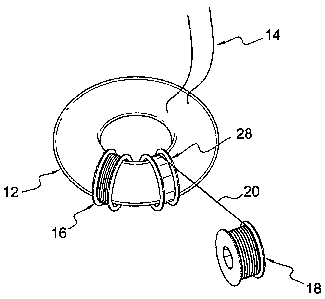
device can include providing a toroidal electrical core 12.
The toroidal electrical core 12 can include electrical leads
14. The inductive device can be configured for use as an
inductor, a choke, a transformer, or the like. The electrical
core 12 can be formed of electrical wire or electrical strip,
for example. The conductive material forming the electrical
core 12 is preferably coated with an electrically insulating
material. The toroidal shaped electrical core 12 provides a
shape about which one or more magnetic components can be
11
CA 02637603 2008-07-16
WO 2007/084963 PCT/US2007/060722
disposed so that the electrical core is at least partially
enveloped by the magnetic components_
The electrical leads 14 can be used to connect the
inductive device to another electrical device, a system or a
circuit. The number of leads extending from the electrical
core can depend on a number of factors, such as, the number of
individual windings, or coils, that constitute the electrical
core component and/or how individual windings are connected
within the electrical core component. Also, the placement of
the leads can be selected as desired depending upon the
requirements of a particular application.
As shown in FIG. 2, the method of making an inductive
device continues with the provision of a bobbin 16 disposed
about the electrical coil. The bobbin 16 is fit loosely
enough about the electrical core 12 so that the bobbin 16 can
easily be rotated about the electrical core 12 to enable
winding of a magnetic component about the electrical core 12.
A lubricant such as Teflon, silicon, or other suitable
lubricating agent can be applied to an outer surface of the
electrical core 12 and/or an inner surface of the bobbin 16 in
order to reduce friction between the bobbin 16 and the
electrical core 12 and thereby reduce or prevent frictional
damage to either component as a result of rotation. The
lubricant may be an electrical insulator.
The bobbin 16 may be formed of plastic, fiber reinforced
plastic, or other suitable material. The bobbin 16 can be
12
CA 02637603 2008-07-16
WO 2007/084963 PCT/US2007/060722
made to be later removable and/or reusable, or it may become a
permanent part of the inductive device. The bobbin 16 may be
formed as a cylinder without shoulders, or as a cylinder with
shoulders as shown. If the magnetic material being wound onto
the bobbin should break, the magnetic material may simply be
reattached to the bobbin and the winding can continue. Also,
multiple. magnetic subcomponents may be wound onto the bobbin
16. The magnetic material may include a single strand wire,
multi-strand wire, a single strip, multiple strips, or a
combination of the above.
FIG. 3 shows a single wire winding arrangement having a
supply reel 18 of wire or strip magnetic material 20. Supply
reel 18 supplies magnetic material 20 for winding onto the
bobbin 16. The winding of the magnetic material 20 onto the
bobbin 16 can be performed manually, automatically, or through
a combination of the above.
In practice, an end of the magnetic material 20 can be
attached to the bobbin 16. The bobbin 16 is then be rotated
about the electrical core 12. As the bobbin 16 rotates about
the electrical core 12, the magnetic material 20 is fed from
the supply reel 18 and onto the bobbin 16 thereby forming a
wound magnetic component about the electrical core 12.
FIG. 3 shows a beginning of winding a single wire onto
the bobbin 16 as, for example, a first magnetic material
sector wound onto the electrical core 12. While a single
supply reel 18 is shown as carrying a single magnetic wire 20,
13
CA 02637603 2008-07-16
WO 2007/084963 PCT/US2007/060722
it should be appreciated that the supply reel may carry a
plurality of wires or strips. In order to increase the
density of the magnetic component, the magnetic wire may
include wires having different shapes and/or different sizes.
For example, the magnetic wire may include round wires having
two different sizes with, for example, a circumference ratio
that is between 5:1 and 6:1. The magnetic wire can include
wire having different cross-sectional shapes, sizes, and/or
cross-sectional areas. It should be appreciated that multiple
wires, or multiple strands, may be used to build an inductive
device according to the method described above, and such use
may require fewer rotations of the bobbin 16 and thereby
contribute to the efficiency of the manufacturing process.
FIG. 4 provides a diagrammatic view of an embodiment
having a source of motive force to engage the bobbin and wind
the magnetic medium onto the electrical coil. In particular,
in addition to the elements described above, FIG. 4 shows a
bobbin rotator 22. The bobbin rotator 22 includes a drive 24
(e.g., a speed-controlled electric motor) and a bobbin drive
wheel 26 attached to a rotatably driven shaft of the drive 24.
In the form shown, the bobbin drive wheel 26 frictionally
engages end flanges of the bobbin 16 and rotates the bobbin 16
about the electrical core 12. The magnetic material 20,
having been attached to the bobbin 16 prior to rotation, is
thus wound onto the bobbin 16, and thereby wound about the
electrical core 12, as the bobbin 16 is rotated by the bobbin
14
CA 02637603 2008-07-16
WO 2007/084963 PCT/US2007/060722
drive wheel 26. The magnetic material 20 may be attached to
the bobbin 16 by any suitable means such as adhesive, adhesive
tape, a fastener, etc. As the magnetic material 20 is wound
onto the bobbin 16, the magnetic material 20 is unwound from
the supply reel 18. The supply reel may rotate freely in
response to the unwinding of the magnetic material 20, or it
may rotate under power. To facilitate engagement with the
bobbin end flanges, the bobbin drive wheel may have an elastic
(e.g., rubber) outer surface which elastically engages the
bobbin flanges.
FIG. 5 provides a view showing a winding of a second
magnetic component onto the electrical coil. In particular,
in addition to the elements described above, a second bobbin
28 is shown. FIG. 5 illustrates a continuation of the
building process, with one completed magnetic component having
been wound onto the first bobbin 16, and a second magnetic
component about to be wound on the second bobbin 28. The
second magnetic component can be wound in the same manner as
described above.
After each bobbin has been wound with magnetic material
as desired, it can be detached from the magnetic material
supply, and the combined wound magnetic component and bobbin
may be held in place on the electrical core by suitable means
such as adhesive, adhesive tape, or an insulative wrapping
material. The construction process of winding a bobbin to a
desired level and then moving on to wind a next bobbin with
CA 02637603 2008-07-16
WO 2007/084963 PCT/US2007/060722
magnetic material can continue until the electrical core is
full with little or no additional room for another bobbin
(i.e., the electrical core may be substantially enveloped or
surrounded by bobbins/magnetic winding components) or until
there is sufficient magnetic material in place for a
contemplated operational characteristic.
FIG. 6 shows two means of winding multiple lengths of
magnetic material onto the electrical core at the same time,
drawing from multiple supply reels or from a single, common
supply reel. In particular, a first means of supplying
multiple wires or strips for winding onto a bobbin (or an
electrical core) may include multiple spools 30, 32, 34 each
supplying a single wire or strip. A second means for
supplying multiple wires or strips for winding onto a bobbin
(or an electrical core) may include a single supply reel 36
supplying multiple wires or strips to wind onto a bobbin (or
an electrical core).
FIGS. 7A-C illustrate several exemplary techniques for
securing completed magnetic components to the annular
electrical core. In particular, FIG. 7A provides a
diagrammatic view of an electrical core 12 (shown in section)
with a bobbin 16 disposed thereabout and a spacer 38 disposed
between an outer surface of the electrical core 12 and an
inner surface of the bobbin 16. A plurality of such spacers
may be fitted, preferably tightly, between the bobbin 16 and
16
CA 02637603 2008-07-16
WO 2007/084963 PCT/US2007/060722
the electrical core 12, thus holding the bobbin in position
retaining it in position about the electrical core.
FIG. 7B provides a diagrammatic view an electrical core
12 with a bobbin 16 disposed thereabout and a separate winding
of magnetic material 40 disposed between an outer surface of
the electrical core 12 and an inner surface of the bobbin 16.
The separate winding of magnetic material 40 may include wire,
strip, sheet material, or the like. Also, the magnetic
material 40 may the same or different from the magnetic
material wound onto the bobbin 16. The magnetic material 40
may act as a wedge or "shim" to help keep the bobbin 16 in
place about the electrical core 12. For example, the magnetic
material 40 may be wound onto the electrical core 12 and then
the bobbin 16 may be slid along the electrical core and over
the magnetic material 40.
FIG. 7C provides a diagrammatic view an electrical core
12 with a bobbin 16 disposed thereabout and an adhesive 42
disposed between an outer surface of the electrical core 12
and an inner surface of the bobbin 16. The adhesive 42 can be
used to hold the bobbin 16 in place about the electrical core
12. The adhesive 42 may be a nonmagnetic adhesive or may be a
magnetic adhesive constituted by an adhesive material
impregnated with magnetic material such as magnetic powder or
particles.
FIG. 8A provides a view of an embodiment having a splayed
magnetic component 44. The splayed magnetic component 44 is
17
CA 02637603 2008-07-16
WO 2007/084963 PCT/US2007/060722
splayed outwardly toward the outer diameter circumference
surface 46 of the electrical core 12. The magnetic component
44 may be formed as a splayed component during winding (by
guiding the magnetic material relative to the bobbin), or
after winding. The splaying may be performed manually,
automatically, or through a combination of the above.
By splaying the magnetic components into a generally
sector shape, as shown in FIG. 8A, the outer portion of the
toroidal electrical core can be more widely covered, thereby
providing greater magnetic efficiency and enhanced magnetic
shielding.
FIG. 8B provides a diagrammatic view of an exemplary
removable bobbin. In particular, a removable bobbin 48
includes a first portion 50 and a second portion 52, separable
from each other at a joint connecting inside end portions 54.
The first portion 50 and the second portion 52 may be joined
by snapping together interlocking members, by applying an
adhesive, by using a fastener, or any other suitable means to
form the aforementioned joint. Also, each of the first
portion 50 and the second portion 52 includes a longitudinal
joint 56 that allows the first portion 50 and the second
portion 52 to each separate into respective halves. The
bobbin is mounted on an electrical core by assembling the two
halves of each portion 50 and 52 about the core and then
joining the portions 50 and 52 together at the portions 54.
The bobbin may be removed by reversing this procedure.
18
CA 02637603 2008-07-16
WO 2007/084963 PCT/US2007/060722
FIG. 9 provides,a view of an embodiment having a toroidal
electrical core with five splayed magnetic sector components
each surrounding the electrical core 12 and having leads 14.
First magnetic components 44 and one or more second magnetic
components 58 (one being shown) are disposed about the
electrical core 12 and circumferentially offset from each
other. The magnetic components 44 and 58 may be formed in a
same or different manner. For example, the magnetic
components 44 may be formed by winding magnetic material onto
a bobbin and splayed as described above, and the magnetic
component 58 may be formed in a sector shape on a jig, then
cut, removed from the jig and disposed about the electrical
core so as to provide a gap in a meridional plane as described
in International Patent Application Publication No.
W02005/086186, incorporated herein by reference.
FIG. 10 provides a view of an embodiment having splayed
magnetic components and non-splayed magnetic components. In
particular, the inductive device of FIG. 10 includes five
splayed magnetic components 60 and two non-splayed, or
cylindrical, magnetic components 62, all wound by the above-
described technique. The splayed magnetic components have a
generally sector shape. The non-splayed magnetic components
62 can readily be wound onto the electrical core 12 after the
splayed magnetic components 60 have been wound, thus
accommodating the decreased amount of space available on the
19
CA 02637603 2008-07-16
WO 2007/084963 PCT/US2007/060722
electrical core after the sector components 60 have been
formed.
FIG. 11 provides a view of an embodiment having splayed
magnetic sector components and non-splayed magnetic sector
components that are interspersed. In particular, FIG. 11
shows an arrangement of alternating splayed magnetic material
component sectors 60 and non-splayed magnetic components 62.
Gaps in the spacing of the splayed and/or non-splayed magnetic
components around the annulus can be very small or
substantial, depending on the desired characteristics. For
example, large gaps can be employed to facilitate cooling of
the magnetic components and the electrical core.
FIG. 12 provides a view of an electrical core with a
straight portion 64. The straight portion 64 is of sufficient
length to allow a bobbin, disposed about the straight portion
64, to rotate easily about the electrical core 12, thus
facilitating the winding of magnetic material. Once a
magnetic component has been wound, it can be slid away from
the straight portion 64 and along the length of the electrical
core to make room for another magnetic component to be wound
at the straight portion.
The straight portion 64 may be formed during winding of
the electrical core 12, or after winding of the electrical
core 12, and it may be permanent or temporary. In the case of
a temporary straight portion, the straight portion may be
CA 02637603 2008-07-16
WO 2007/084963 PCT/US2007/060722
returned to a rounded shape after winding of the magnetic
components thereon is complete.
FIG. 13 provides a view of an embodiment having a
toroidal electrical core onto which a magnetic component
having a toroidal shape has been wound. In particular, the
inductive device of FIG. 13 includes an electrical core 12,
leads 14 connected to the electrical core, and a magnetic
component 66 wound about the electrical core 12 in the manner
described above. The internal hole of the electrical coil is
substantially filled by the magnetic component 66.
FIG. 14 provides a view of an embodiment having a
toroidal electrical core onto which two magnetic components 66
each having a toroidal shape have been wound in the manner
described above. The inductive device of FIG. 14 includes an
electrical core 12 (with leads not shown) andtwo magnetic
components 66 each wound about the electrical core 12. The
two magnetic components 66 are disposed about generally
opposite side portions of the electrical core 12_
FIG. 15 provides a view of an embodiment having a
toroidal electrical core onto which a plurality of magnetic
components 66 each having a toroidal shape have been wound as
previously described. The inductive device of FIG. 15
includes an electrical core 12 (with leads not shown) and
multiple (3 or more, here 7) magnetic components 66 wound
about the electrical core 12. Each of the magnetic components
21
CA 02637603 2008-07-16
WO 2007/084963 PCT/US2007/060722
66 disposed about the electrical core 12 is circumferentially
offset from the others.
FIG. 16 provides a view of an embodiment having an
electrical core 12 with a plurality of magnetic components 66
disposed thereabout. The plurality of magnetic components are
circumferentially offset from each other, and formed by
winding onto the electrical core 12 with a bobbin as described
above. The wound magnetic components provide an effective
magnetic gap (specifically, a distributed gap) by virtue of
the fact that the winding follows a non-circular path whereas
magnetic flux is circular and is thus forced to "jump" between
successive turns of the winding as they traverse the circular
flux path.
FIG. 17 is a side view of an exemplary inductive device 68
having an electrical coil 76 formed in a generally elongated
toroidal configuration and leads 70 connected to the
electrical coil. The electrical coil 76 is elongated along an
elongation direction indicated by arrow 72. The inductive
device 68 also includes a magnetic component 73 wound about
the electrical coil 76 in a winding direction transverse to
the electrical winding direction of the electrical coil 76 and
without passing through an inner opening 74 of the electrical
coil 76. Optionally, additional magnetic material, such as
wire, strip, powder, magnetic adhesive, or the like, may be
disposed in the inner opening 74.
22
CA 02637603 2008-07-16
WO 2007/084963 PCT/US2007/060722
FIG. 18 shows an elongated electrical coil having an
essentially cylindrical sector form. In particular, a cylindrical
sector 78 electrical component includes an electric winding 80
having a sector shaped end portion 82 and elongated sides 84.
The electric winding 80 is connected via electrical leads 86.
The cylindrical sector 78 can be formed by winding electrical
wire onto a jig. Adhesive material may be used to bind the
electrical wire during or after formation of the cylindrical
sector 78 to maintain the desired form. Also, tape or other
binding material may be used to secure the cylindrical sector
78 in its wound configuration.
It should be appreciated that magnetic material in the
form of a wire, strip, powder material, or the like, could be
placed within an inner area formed by loops of the electrical
coil 78 either as a continuous component or in sections.
FIG. 19 shows top and end views of the coil shown in FIG. 18.
In particular, the cylindrical sector 78 electrical component
includes an electric winding 80 having a sector shaped end
portion 82 and elongated sides 84. The electric winding 80 is
connected via electrical leads 86. The sector shaped
configuration of electrical component 78 permits multiple
cylindrical sector shaped electrical components to be arranged
to form an overall cylindrical structure.
FIG. 20 provides an end view of an embodiment having
cylindrical sector components disposed to form a structure having a
generally cylindrical shape. In FIG. 20, an inductive device 88
23
CA 02637603 2008-07-16
WO 2007/084963 PCT/US2007/060722
includes a plurality of elongate electrical components 78, each
of a substantially cylindrical sector form. The plurality of
elongate electrical components 78 are arranged to form a
substantially cylindrical structure. The spacing between
adjacent components may be filled with an insulative adhesive
or potting material to assure structural integrity of the
assembled components. Although the components are shown
spaced from each other, such spacing is not strictly necessary
so long as adjacent sides of the components are not in
electrical contact. For this purpose, any suitable insulating
material may be disposed between the components, or the
windings may be coated with insulation. Also, magnetic
material in the form of wire, narrow strip, powder material,
or the like, could be installed in a center area of the device
defined by the portions of the cylindrical sectors (or wedges)
where they converge in the middle.
FIG. 21 provides an end view of an embodiment of similar
cylindrical sector shaped elongated winding segments 78 placed into
approximate position with each other and having electrical lead
connections 86.
In practice, the electrical components 78 can be
connected in various ways, such as individually, in series, in
parallel, or in group arrangements as may be suitable for a
contemplated use of the embodiment. FIG. 22 shows an
arrangement in which the electrical components 78 are
connected in series. FIG. 23 provides an end view of a
24
CA 02637603 2008-07-16
WO 2007/084963 PCT/US2007/060722
transformer arrangement having a primary and a secondary, each
comprised of a group of cylindrical sector shaped electrical winding
components connected in a series configuration. In particular,
transformer 94 includes input leads 96 connected to a group of
series-connected elongate electrical components 99 forming the
primary, and output leads 98 connected to a group of series-
connected elongate electrical components 97 forming the
secondary. Each of the first and second elongate electrical
components 97, 99 is of substantially cylindrical sector form,
and the elongate electrical components are collectively
arranged to form a substantially cylindrical shape.
In operation, electrical energy provided to the primary
leads 96 is transformed by the inductive coupling between the
primary electrical coils 99 and the secondary electrical coils
97 and output via leads 98.
FIG. 24 provides an end view of a transformer arrangement
having a primary and a secondary, each comprised of a group of
cylindrical sector shaped electrical winding components connected in
a series configuration. in particular, transformer 100 includes
input leads 102 connected to a group of parallel-connected
elongate electrical components 103 forming the primary, and
output leads 104 connected to a group of parallel-connected
elongate electrical components 105 forming the secondary.
Each of the first and second elongate electrical components
103, 105 is of substantially cylindrical sector form, and the
CA 02637603 2008-07-16
WO 2007/084963 PCT/US2007/060722
elongate electrical components are collectively arranged to
form a substantially cylindrical shape.
FIG. 25 provides an end-view of another transformer
arrangement combining cylindrical sector shaped coils 110 and
elongated toroidal coils 112. The coils 110 and 112 are
similar to the electrical coils shown in FIGS. 18 and 17,
respectively.
FIG. 26 provides a view of an embodiment having a
cylindrical arrangement of electrical coil components (as
exemplified in any of FIGS. 20-25) wrapped on the outside with
magnetic material. The magnetic component 120 may be formed
of magnetic wire, magnetic strip, or other suitable magnetic
material. Magnetic wire or strip material would preferably be
wound transverse to the electrical windings of the cylindrical
core 118. The cylindrical core can be connected to a circuit
via electrical leads 124 (only two of which are shown in the
drawing). It should be appreciated that the number of leads
may vary depending on a contemplated use of the embodiment and
other factors such as number of electrical windings within the
device.
The magnetic component 120 serves to contain the magnetic
flux generated within the cylindrical core 118 and direct the
flux along a path about the cylindrical core 118. Inductive
coupling between the individual coils of the cylindrical core
is provided by the outer magnetic component and air (or
26
CA 02637603 2008-07-16
WO 2007/084963 PCT/US2007/060722
magnetic material, if desired) inside the cylindrical core
118.
FIG. 27 provides a view of an embodiment having
electrical coil components with a rotor placed at the center
of the assembled coil components such that the rotor is
surrounded by the electrical coil assemblage. In particular,
an electric motor 126 includes stator coils 128 and a rotor
130. The stator coils 128 can include an inductive device 68,
a cylindrical sector 78, or a combination of the two. The
rotor can take the form of a shaft having grooves formed along
its length or any other suitable for that will provide
electromagnetic interaction with the stator to effect rotation
of the rotor. Of course, generator action may also be
provided, as will readily be understood by those skilled in
the art. Other embodiments can provide linear motion.
The assembled stator coils 128 may be wrapped on the
outside with magnetic material, such as wire or strip
material. Also, the stator coils 128 may be held together
using potting material, clamps, a tube made of ceramic or
other suitable nonmetallic material, etc.
FIG. 28 provides a diagrammatic view of a magnetic
pattern member 132 composed of magnetic wire formed into a
serpentine arrangement. Such a pattern member and one or more
toroidal electrical components can be wound in the same
direction on a common form, thus facilitating the manufacture
of a toroidal inductive device with the magnetic pattern
27
CA 02637603 2008-07-16
WO 2007/084963 PCT/US2007/060722
member serving as a magnetic component of the device. The
magnetic pattern member 132 is formed such that adjacent
lengths 134 of a continuous, elongate magnetic material 136
extend in alternating directions transverse to a longitudinal
direction 138 of the pattern member. The continuous material
may be constituted of magnetic wire or other elongate magnetic
material, such as magnetic strip material, and may be held in
shape by adhesive material, for example, such that the pattern
member essentially becomes a strip-like material having
lengths 134 running transverse to the longitudinal direction
of the "strip."
FIGS. 29-30 illustrate another technique of forming a
pattern member.from magnetic wire. in particular, a helical
coil 140 of magnetic wire is first formed along a forming
direction 142. Next the coil 140 is flattened, and optionally
compressed longitudinally, to produce a substantially flat
member of magnetic material 144, where adjacent portions of
material forming the member extend substantially transversely
to the forming direction 142. Like member 132, the member 144
may be held in shape by adhesive material or any other
suitable means.
FIG. 31 provides a diagrammatic illustration of an
exemplary inductive device winding apparatus 149. The
apparatus 149 includes a mandrel 150, magnetic material
shaping devices (indicated diagrammatically by arrows 151), a
winding apparatus 152 having a motor 154 and a shaft 156, a
28
CA 02637603 2008-07-16
WO 2007/084963 PCT/US2007/060722
supply rail 158, and magnetic material 160 supplied from the
supply reel. Magnetic material 160 is constituted by a
magnetic pattern member formed as shown in FIGS. 28-30.
To form a magnetic component, magnetic material 160 is
attached to the mandrel 150 and winding apparatus 152 is
operated to rotate mandrel 150 to wind the magnetic material
160 onto the mandrel. The magnetic strip is advanced
lengthwise as it is wound onto the mandrel 150, its adjacent
portions 134 or the like extending transversely to the winding
direction. The surface of mandrel 150 can be of concave form,
as shown, corresponding to the inner surface of the desired
toroidal shape of a finished toroidal inductive device.
After winding a desired length of the magnetic member 160
onto the mandrel 150, one or more coils of electrical wire may
be wound over the magnetic material present on the mandrel to
form a toroidal electrical core. Finally, one or more layers
of magnetic material 160 can be wound over the electrical
winding(s). As the further magnetic material is being wound
about the mandrel 150, the magnetic material shaping devices
151 can shape and form the magnetic material so as to embrace
and conform to the underlying material on the mandrel. The
shaping devices 151 may be simple manual tools configured to
press the advancing magnetic material so as to conform with
the outer surface of the underlying material on the mandrel,
or they may be automatically controlled shaping tools such as
computer-controlled shaping roller devices. It will be
29
CA 02637603 2008-07-16
WO 2007/084963 PCT/US2007/060722
appreciated that a shaping tool may also be employed during
the first magnetic material winding step, before winding the
electrical core. FIG. 32 is a diagrammati.c view illustrating
a magnetic pattern member 162 that has been shaped into an
arcuate form to conform to an electrical coil having a
generally toroidal form.
According to another approach, the magnetic pattern
member could be formed "on the fly" as it is being fed from a
spool of wire to the mandrel 150.
FIG. 33 is a diagrammatic cut-away view of a toroidal
transformer 165 formed by the technique described in
connection with FIG. 31. The transformer 165 includes a
magnetic component 166 composed of inner and outer magnetic
pattern members wound on a mandrel and shaped to conform to an
intermediate electrical core also wound on the mandrel, as
described above_ Leads 170 and 172 connect to windings of the
electrical core 168. FIG. 34 is a diagram of the transformer
taken from the side. FIG. 35 is a corresponding plan view
diagram.
FIG. 36 depicts the use of a bobbin 164 disposed about an
elongated electrical core 166 for winding a magnetic material
about the core at its outer cross-dimension. The electrical
core 166 is elongated in an elongation direction 168 and may
include one or more electrical windings. Magnetic material
(e.g., wire) 170 is wound onto the bobbin 164 in a winding
direction 172 transverse to the elongation direction 168 of
CA 02637603 2008-07-16
WO 2007/084963 PCT/US2007/060722
the core (i.e., transverse to the lengthwise direction of the
electrical core wires within the bobbin). An area 174 is
defined by an inside surface of the elongated electrical core
166. As shown in FIG. 36, an entire outer cross-dimension of
the core 166 is received within the bobbin 164 (the bobbin 164
does not pass through the area 174 of the inner core opening),
whereby the resulting wound structure will resemble that shown
in FIG. 17. The bobbin may be retained as part of the
finished device or removed, as described in connection with
earlier embodiments.
FIGS. 37 and 38 show two views of an exemplary inductive
device having heavy current elements in the center with high-
tension elements on both sides. In particular, inductive
device 176 having a toroidal shape 178 includes a first
primary winding 180, a second primary winding 182, a first
secondary winding 184, a second secondary winding 186, and
leads 188.
The first and second secondary windings (184 and 186) are
disposed adjacent to each other and in the center of the
torus. The first primary winding 180 is disposed on an inner
circumferential portion of the toroidal shape and the second
primary winding 182 is disposed on an outer circumferential
portion of the toroidal shape. The inductive device 176 may
also include a magnetic component 187 wrapped about the
composite core composed of the primary and secondary windings.
Alternatively, magnetic components may be wound onto the
31
CA 02637603 2008-07-16
WO 2007/084963 PCT/US2007/060722
electrical core using a bobbin in the manner described in
connection with FIGS. 1-12.
While this invention has been described in conjunction
with a number of embodiments, it will be apparent to those
skilled in the art that many alternatives, modifications and
variations are possible without departing from the principles
and spirit of the invention.
32