Language selection

Search

Patent 2637619 Summary

Third-party information liability

Some of the information on this Web page has been provided by external sources. The Government of Canada is not responsible for the accuracy, reliability or currency of the information supplied by external sources. Users wishing to rely upon this information should consult directly with the source of the information. Content provided by external sources is not subject to official languages, privacy and accessibility requirements.

Claims and Abstract availability

Any discrepancies in the text and image of the Claims and Abstract are due to differing posting times. Text of the Claims and Abstract are posted:

  • At the time the application is open to public inspection;
  • At the time of issue of the patent (grant).
(12) Patent Application: (11) CA 2637619
(54) English Title: FLOATING OPTIC ACCOMMODATING INTRAOCULAR LENS
(54) French Title: LENTILLE INTRA-OCULAIRE A ACCOMMODATION OPTIQUE FLOTTANTE
Status: Deemed Abandoned and Beyond the Period of Reinstatement - Pending Response to Notice of Disregarded Communication
Bibliographic Data
(51) International Patent Classification (IPC):
  • A61F 02/16 (2006.01)
(72) Inventors :
  • CUMMING, J. STUART (United States of America)
  • DELL, STEVEN J. (United States of America)
  • SOISETH, JONATHAN R. (United States of America)
(73) Owners :
  • C & C VISION INTERNATIONAL LIMITED
(71) Applicants :
  • C & C VISION INTERNATIONAL LIMITED (Iran (Islamic Republic of))
(74) Agent: SMART & BIGGAR LP
(74) Associate agent:
(45) Issued:
(86) PCT Filing Date: 2007-02-20
(87) Open to Public Inspection: 2007-08-30
Examination requested: 2011-03-08
Availability of licence: N/A
Dedicated to the Public: N/A
(25) Language of filing: English

Patent Cooperation Treaty (PCT): Yes
(86) PCT Filing Number: PCT/US2007/004436
(87) International Publication Number: US2007004436
(85) National Entry: 2008-07-23

(30) Application Priority Data:
Application No. Country/Territory Date
11/360,019 (United States of America) 2006-02-21

Abstracts

English Abstract


An accommodating intraocular lens (10) comprising a flexible body (12), a
flexible optic (14) which is moveable anteriorly and posteriorly relative to
the lens body, and a weakened portion connecting the optic to the body. The
body may have extending centration and fixation loops (24) on its distal ends.


French Abstract

La présente invention concerne une lentille intra-oculaire à accommodation comprenant un corps flexible, un élément optique flexible qui est partiellement mobile antérieurement et postérieurement par rapport au corps de la lentille, et une partie affaiblie connectant l'élément optique au corps. Le corps peut comprendre un centrage extensible et des boucles de fixation sur son extrémité distale.

Claims

Note: Claims are shown in the official language in which they were submitted.

WHAT IS CLAIMED IS:
1. An accommodating intraocular lens comprising a flexible body, and a
flexible optic
mounted to and surrounded by the body by a structure allowing the lens optic
to move
anteriorly and posteriorly relative to the lens body.
2. A lens as in Claim 1 wherein there is a plurality of straps between the
body and
optic.
3. A lens as in Claim 1 wherein a continuous skirt surrounds the optic
connecting it to
the lens body.
4. A lens as in Claim 1 further including loops extending from outer ends of
the body.
5. A lens as in Claim 1 wherein a posterior side of the body includes ridges.
6. An accommodating intraocular lens comprising a flexible body and a flexible
optic;
the flexible optic being mounted to the body by a plurality of thin flexible
straps disposed
between the optic and the body, the straps being approximately 0.5 mm long
radially and
approximately 0.1 mm thick, and the lens including a plurity of fixation loops
attached to ends
of the body.
7. A lens as in Claim 6 including haptics with a weaked thinned or hinged
portion
within the lens body allowing the lens optic, its surrounding lens body part
central to the
hinges, to move forward and backward relative to the outer ends of the
haptics.
8. A lens as in Claim 6 wherein the outer ends of the haptics include loops to
securely
fixate and center the lens.
9. A lens as in Claim 6 wherein the optic is constructed to optically deform,
with
ciliary muscle contraction, to enhance near vision.
10. A lens as in Claim 6 wherein the lens body has anterior projections to
separate the
anterior human lens capsule from the lens body, thereby creating a space for
the optic to move
foreward upon ciliary muscle contraction.
-5-

Description

Note: Descriptions are shown in the official language in which they were submitted.


CA 02637619 2008-07-23
WO 2007/098173 PCT/US2007/004436
FLOATING OPTIC ACCOMMODATING INTRAOCULAR LENS
BACKGROUND
100011 Intraocular lenses have for many years had a design of a single optic
with loops
attached to the optic to center the lens and fixate it in the empty capsular
bag of the human eye.
In the mid '80s plate lenses were introduced, which comprised a silicone lens,
10.5 mm. in
length, witli a 6 mm. optic. These lenses could be folded but did not fixate
well in the capsular
bag, but resided in pockets between the anterior and posterior capsules. The
first foldable
lenses were all niade of silicone. In the mid 1990s an acrylic material was
introduced as the
optic of lenses. The acrylic lens comprised a biconvex optic with a straight
edge into which
were inserted loops to center the lens in the eye and fixate it within the
capsular bag.
{0002] Recently accommodating intraocular lenses have been introduced to the
market,
which generally are modified plate haptic lenses and, like the silicone plate
haptic lenses, have
no clear demarcation between the junction of the plate with the optic's
posterior surface. A
plate liaptic lens may be defined as an intraocular lens having two or more
plate haptics where
combined junctions with the optic represent one quarter or more of the
circumference of the
optic.
100031 Flexible acrylic material has gained significant popularity among
ophthalmic
surgeons. In 2003 for example more than 50% of the intraocular lenses
implanted had acrylic
optics. Hydrogel lenses have also been introduced. Both the acrylic and
hydrogel materials
are incapable of muitiple flexions without fracturing.
(0004] The advent of an accommodating lens which functions by moving the optic
along the axis ofthe eye by repeated flexions somewhat limited the materials
from which the
lelis could be made. Silicone is the ideal material, since it is flexible and
can be bent probably
several million times without showing any damage. Additionally a groove or
hinge can be
placed across the plate adjacent to the optic as part of the lens design to
facilitate movement of
the optic relative to the outer ends of the haptics. An example accommodating
lens of this
nature is disclosed in U.S. Patent 6,387,126 in the name of J. Stuart Cumming.
SUMMARY OF THE INVENTION
(0005] According to the present invention a new form of accommodating
intraocular
lens having a lens body and optic is provided which can be thought of as
including a "floating
piston optic" witli plural straps or fingers, such as four, between the lens
body and optic to
allow the optic to move anteriorly and posteriorly in a piston fashion in
response to the
pressure gradient created with accommodation.
-1-

CA 02637619 2008-07-23
WO 2007/098173 PCT/US2007/004436
j0006) Thus, it is a feature of the present invention to provide a new form of
accommodating lens.
BRIEF DESCRIPTION OF THE DRAWINGS
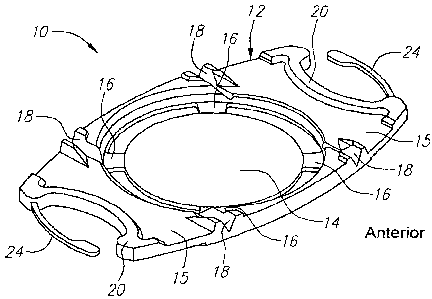
100071 Figure 1 is a prospective view of the front or anterior side of the
lens according
to the present invention.
100081 Figure 2 is a plan view of the anterior side.
100091 Figure 3 is a plan view of the back or posterior side of the lens.
100101 Figure 4 is a side view.
100111 Figure 5 is an end view.
100121 Figure 6 is a cross-sectional view along lines 6-6 of Figure 2.
100131 Figure 7 is a perspective view of the back or posterior side of the
lens.
DESCRIPTION OF PREFERRED EMBODIMENT
100141 Turning now to the drawings, Figure 1 is a perspective view of the
present lens
includitlg a lens body or plate 12 and optic 14. The body 12 includes haptics
15. The body
12 and optic 14 are fornled of silicone or other suitable flexible material.
Flexible straps 16 are
provided between the body 12 and the periphery or outer diameter of the optic
14. The straps
may be 0.5 mni long in the radial direction and 0.1 mm thick so as to
essentially create an
"piston optic" 14 supported by the straps. In yet another iteration the lens
may have a
continuous skirt surrounding the optic and connecting the optic to the lens
body. The optic 14
typically can have a diameter of 4.5 mm, atypical width of the overall Iens 10
on the short side
is 6.1 mm ai1d the typical length from end to end (not including fixation
fingers) on the long
side is 10.5 niin.
[0015] The body 12 and optic 14, as well as outer thickened footplate ends 20,
are
fomied of silicone or other suitable flexible material. The lens 10 also
includes fixation loops
24 of polymide or similar inaterial. A typical outer loop-to-loop length is
11.5 mm. The
tliickened ends 20 fully engulf the fixation loops 24 in the silicon thus to
provide a strong
matrix to hold the loops 24. There is an additional function of these
thickened areas of the
plate. They also serve to elevate the anterior capsule of the human lens away
from the optic
and fronl the posterior capsule after the cataract has been removed. This may
serve to reduce
capsular opacification and contraction.
100161 The straps 16 function as a pseudo-zonular complex, allowing the optic
to move
anteriorly and posteriorly. The approximately 0.7 mm wide straps are a point
of relative
weakness in the plane of the lens body 12 encircling the optic 14, thereby
allowing the entire
-2-

CA 02637619 2008-07-23
WO 2007/098173 PCT/US2007/004436
optic 14 to lierniate forward (anteriorly) from its far posterior position in
a translational
forward movement. This feature is enhanced by keeping the mass of the optic 14
to a
mininium as described below. This new mechanism may boost the effect of the
other features
of the lens. Rather than a fluid-filled sac pushing through an aperture as in
some prior lenses,
the present lens involves a deformable solid optic moving anteriorly and
posteriorly through a
weak area (16) in the plate or body 12. Hinges 18 on the anterior side of the
body 12 hinging
the haptics 15 further facilitate movement of the optic with ciliary muscle
contraction.
[00171 Another feature allowing the present lens to accommodate is that the
optic 14
can be deformable and constructed with a lower durometer than previously built
into any lens.
The surrounding plate 12 preferably is made of a higher, standard durometer
material, similar
to the eyeonics Inc. AT45 lens (which is durometer 48). The optic 14 itself is
not required to
contribute to the strLictural stability of the lens and, therefore, the optic
14 can be extremely
soft. In addition to forward axial translation, the bending or deformation of
the optic 14 with
accommodation will induce power change. This may result in the bending of the
optic to be
accentuated. This feature is further enhanced by maintaining the optic very
thin since a thinner
optic will bend niore than a thick optic for any given level of force applied.
An example range
of optic 14 center thicknesses is about 0.38 mm to 1.07 mm for a diopter range
of 10 to 33. A
typical common diopter of the optic of the present lens is 22 diopters and
which has a thickness
of 0.73 mm. As a coniparison, the AT 45 noted earlier in a 22 diopter has a
thickness of 0.88
tnm, and a newer AT-45SE is 0.98 mm.
100181 A 4.5 rnrr- diai-neter optic 14 and with a reduced edge thickness of
0.1 to 0.2 mm
for example can be provided. The index of refraction can be increased and this
will accentuate
this feature even further. The fact that this optic 14 is symmetrically
tethered to the plate 12 in
all meridians by the straps can mean that power changes in the curvature are
also symmetrical,
meaning spherical power change as opposed to astigmatic changes found in some
other lenses.
Optic flexure is a new and poorly understood phenomenon, and unwanted optical
distortion
may be encountered resulting in poor vision either at near or far distances,
in which case the
duronieter of the material will need to be raised.
100191 The present lens can be easily foldable with forceps or an injector. A
pre-
loaded system is preferable.
[00201 An additional feature is the incorporation of a ridge or ridges 40 on
the back
surface (posterior side) of the plate 12 and/or haptic arm as the case may be
as seen in Figs. 3
and 7. These ridges traverse the plate and completely encircle the optic
around the perimeter
of the lens body. There is an additional ridge central to the first ridge
traversing the plate
-3-

CA 02637619 2008-07-23
WO 2007/098173 PCT/US2007/004436
adjacent to the optic straps. The purpose of these ridges is to prevent
proliferation of lens
epitlielial cells into the area behind the plate or optic. For plate lenses
this can dramatically
reduce the incidence of capsular contraction. Epithelial cells will be
prevented from migrating
under the plate and undergoing a fibrotic contraction. Furthermore, the square
edge of the
loops, plate haptics and the square edge of the optic further prOtect against
cells migrating in
frorn the sides of the plate.
100211 While an embodiment of the present invention as been shown and
described,
various niodifications may be made without departing from the scope of the
present invention,
and all such modifications and equivalents are intended to be covered.
-4-

Representative Drawing
A single figure which represents the drawing illustrating the invention.
Administrative Status

2024-08-01:As part of the Next Generation Patents (NGP) transition, the Canadian Patents Database (CPD) now contains a more detailed Event History, which replicates the Event Log of our new back-office solution.

Please note that "Inactive:" events refers to events no longer in use in our new back-office solution.

For a clearer understanding of the status of the application/patent presented on this page, the site Disclaimer , as well as the definitions for Patent , Event History , Maintenance Fee  and Payment History  should be consulted.

Event History

Description Date
Inactive: Dead - No reply to s.30(2) Rules requisition 2015-01-19
Application Not Reinstated by Deadline 2015-01-19
Deemed Abandoned - Failure to Respond to Maintenance Fee Notice 2014-02-20
Inactive: Abandoned - No reply to s.30(2) Rules requisition 2014-01-17
Inactive: S.30(2) Rules - Examiner requisition 2013-07-17
Amendment Received - Voluntary Amendment 2013-05-02
Amendment Received - Voluntary Amendment 2013-01-25
Inactive: S.30(2) Rules - Examiner requisition 2012-08-08
Letter Sent 2011-03-21
Request for Examination Requirements Determined Compliant 2011-03-08
Request for Examination Received 2011-03-08
All Requirements for Examination Determined Compliant 2011-03-08
Inactive: Cover page published 2008-11-10
Inactive: Notice - National entry - No RFE 2008-10-23
Inactive: First IPC assigned 2008-09-09
Application Received - PCT 2008-09-08
National Entry Requirements Determined Compliant 2008-07-23
Application Published (Open to Public Inspection) 2007-08-30

Abandonment History

Abandonment Date Reason Reinstatement Date
2014-02-20

Maintenance Fee

The last payment was received on 2013-01-18

Note : If the full payment has not been received on or before the date indicated, a further fee may be required which may be one of the following

  • the reinstatement fee;
  • the late payment fee; or
  • additional fee to reverse deemed expiry.

Patent fees are adjusted on the 1st of January every year. The amounts above are the current amounts if received by December 31 of the current year.
Please refer to the CIPO Patent Fees web page to see all current fee amounts.

Fee History

Fee Type Anniversary Year Due Date Paid Date
Basic national fee - standard 2008-07-23
MF (application, 2nd anniv.) - standard 02 2009-02-20 2009-02-03
MF (application, 3rd anniv.) - standard 03 2010-02-22 2009-12-16
MF (application, 4th anniv.) - standard 04 2011-02-21 2010-12-15
Request for examination - standard 2011-03-08
MF (application, 5th anniv.) - standard 05 2012-02-20 2011-12-20
MF (application, 6th anniv.) - standard 06 2013-02-20 2013-01-18
Owners on Record

Note: Records showing the ownership history in alphabetical order.

Current Owners on Record
C & C VISION INTERNATIONAL LIMITED
Past Owners on Record
J. STUART CUMMING
JONATHAN R. SOISETH
STEVEN J. DELL
Past Owners that do not appear in the "Owners on Record" listing will appear in other documentation within the application.
Documents

To view selected files, please enter reCAPTCHA code :


To view images, click a link in the Document Description column. To download the documents, select one or more checkboxes in the first column and then click the "Download Selected in PDF format (Zip Archive)" or the "Download Selected as Single PDF" button.

List of published and non-published patent-specific documents on the CPD .

If you have any difficulty accessing content, you can call the Client Service Centre at 1-866-997-1936 or send them an e-mail at CIPO Client Service Centre.


Document
Description 
Date
(yyyy-mm-dd) 
Number of pages   Size of Image (KB) 
Claims 2008-07-22 1 40
Abstract 2008-07-22 2 75
Description 2008-07-22 4 208
Drawings 2008-07-22 2 56
Representative drawing 2008-10-23 1 15
Description 2013-01-24 5 217
Claims 2013-01-24 1 28
Reminder of maintenance fee due 2008-10-22 1 115
Notice of National Entry 2008-10-22 1 208
Acknowledgement of Request for Examination 2011-03-20 1 189
Courtesy - Abandonment Letter (R30(2)) 2014-03-16 1 164
Courtesy - Abandonment Letter (Maintenance Fee) 2014-04-16 1 172
PCT 2008-07-22 9 297
PCT 2010-08-02 1 38