Note: Descriptions are shown in the official language in which they were submitted.
CA 02637660 2008-07-17
WO 2007/087342 PCT/US2007/001872
SIDE HANDLES FOR A CARTON
BACKGROUND OF THE INVENTION
The present invention generally relates to a carrier or carton with handle
features.
Cartons, such as paperboard cartons, used to hold, carry, or dispense articles
are well known. These cartons usually are formed or assembled by folding a
paperboard carton blank that has been cut and scored in selected areas to
provide
desired features and characteristics. These features often include tear lines,
handles,
opening features, dispensers, and other well-known attributes.
For example, a.variety of carton handles are known. Nonetheless, there is
always a desire for handles that provide a new balance of properties.
BRIEF SUMMARY OF SOME ASPECTS OF THE INVENTION
In accordance with one aspect of the present invention, handle features of a
carton can help to ease the burden of lifting and carrying the carton. The
handle
features can be side handles that are disposed at opposite ends of the carton.
In accordance with another aspect of the present invention, the blank from
which the carton can be erected can be configured to minimize the amount of
paperboard utilized (e.g., as compared to conventional twin stack carton
designs)
while maintaining at least sufficient functionality.
According to one aspect of the present invention, a carton includes a
plurality
of panels that extend at least partially around an interior of the carton. The
plurality of
panels includes a first panel, and at least one end flap is foldably connected
to the first
panel. A reinforcement panel can be in an overlapping relationship with at
least a
portion of the end flap. More specifically, the reinforcement panel can be in
an
overlapping relationship with at least a portion of a handle panel, with the
handle
panel being a part of the end flap that typically is adjacent to a handle
opening that is
at least partially defined in the end flap. The reinforcement panel may be
adhered to
the handle panel. The reinforcement panel can be foldably connected to an edge
of
the handle panel that is distant from the handle opening. Optionally, a
closure flap
1
CA 02637660 2008-07-17
WO 2007/087342 PCT/US2007/001872
can be provided for closing the handle opening, and an edge of the
reinforcement
panel can extend along, and be shaped substantially like, at least a portion
of an edge
of the handle opening.
The first panel can be a bottom panel of the carton, and the end flap can be a
bottom end flap. The plurality of panels, which extends at least partially
around the
interior of the carton, can include a side panel. A side end flap, which at
least partially
closes an end of the carton, can be foldably connected to the side panel. The
reinforcement panel can be connected to (e.g., releasably adhered to) the side
end flap.
In one example, the reinforcement panel was originally struck from the side
end flap.
The bottom end flap can include an intermediate panel that is positioned
between the bottom panel and the handle panel. In one example, a connection
(e.g.,
formed by adhesive material) between the intermediate panel and the side end
flap is
stronger than the connection (e.g., formed by adhesive material) between the
reinforcement panel and the side end flap, so that the handle panel can be
pivoted
(e.g., folded) away from the side end flap while the intermediate panel
remains
connected to (e.g., adhered to) the side end flap.
The reinforcement panel can be a first reinforcement panel, and the edge of
the
handle panel, to which the first reinforcement panel is foldably connected,
can be a
first edge of the handle panel. The carton can further include a second
reinforcement
panel that is in an overlapping relationship with at least a portion of the
handle panel.
The second reinforcement panel can be foldably connected to a second edge of
the
handle panel that is distant from the handle opening, and the first and second
edges of
the handle panel can be opposite from one another.
In accordance with one aspect of the present invention, a carton includes a
plurality of panels that extend at least partially around an interior of the
carton, and
first and second handle flaps are each at least indirectly pivotably connected
to the
plurality of panels for pivoting in opposite directions away from the
plurality of
panels. In accordance with this aspect, the handle flaps are spaced apart from
one
another, and each of the handle flaps defines a handle opening. Optionally,
the handle
openings are respectively closed by closure flaps that extend into the handle
openings.
The carton can include bottom end flaps respectively foldably connected to
opposite
2
CA 02637660 2008-07-17
WO 2007/087342 PCT/US2007/001872
ends of a bottom panel of the carton, with the first handle flap being
connected (e.g.,
foldably connected) to one of the bottom end flaps, and the second handle flap
being
connected (e.g., foldably connected) to the other bottom end flap. Optionally,
the
handle flaps can be reinforced.
According to one aspect of the present invention, a blank includes a plurality
of panels that are respectively foldably connected to one another, a first end
flap
foldably connected to a first panel of the plurality of panels, and a second
end flap
foldably connected to a second panel of the plurality of panels. The first end
flap at
least partially defines a handle opening, and the second end flap includes a
reinforcement panel that is foldably connected to the first end flap. The
blank can
further include a third end flap foldably connected to a third panel of the
plurality of
panels, with the third end flap including a second reinforcement panel that is
foldably
connected to another edge of the first end flap.
. In accordance with another aspect of the present invention, a blank includes
a
plurality of panels that are respectively foldably connected to one another,
and first
and second end flaps are respectively connected to first and second panels of
the
plurality of panels. The first end flap comprises a handle panel, which may
have a
handle opening proximate thereto. A reinforcement panel is in an overlapping
relationship with, and adhered to, at least a portion of the handle panel. The
reinforcement panel was struck from the second end flap, so that the second
end flap
defines an opening at least partially resulting from the reinforcement panel
having
been struck from the second end flap. The reinforcement panel may be foldably
connected to an edge of the first end flap.
A second reinforcement panel can be in an overlapping relationship with, and
adhered to, at least a portion of the first end flap. The second reinforcement
panel was
struck from a third end flap, so that the third end flap defines an opening at
least
partially resulting from the second reinforcement panel having been struck
from the
third end flap.
One aspect of the present invention is the provision of a method of forming a
construct, such as a carton or an improved blank, from an initial blank. In
accordance
with an exemplary method, a blank is provided so that the blank includes a
plurality of
3
CA 02637660 2010-04-12
panels that are respectively foldably connected to one another, a first end
flap foldably
connected to a first panel of the plurality of panels, and a second end flap
foldably
connected to a second panel of the plurality of panels. The first end flap at
least
partially defines a handle opening, and the second end flap includes a
reinforcement
panel that is foldably connected to the first end flap. The exemplary method
includes
forming a reinforced handle. The forming of the reinforced handle can include
arranging the first end flap and the reinforcement panel in an overlapping
arrangement
with respect to one another so that the reinforcement panel reinforces at
least a portion
of the first end flap that is proximate the handle opening. The arranging can
include
folding the reinforcement panel relative to the first end flap. In one
example, the
arranging includes striking the reinforcement panel from the second end flap.
The
striking can include tearing along at least one tear line that at least
partially defines the
reinforcement panel in the second end flap.
According to one aspect of the present invention there is provided a carton
characterized in that a plurality of panels including a first panel, the first
panel disposed
between a second panel and a third panel; at least a first end flap foldably
connected to
the first panel along a fold line, with the first end flap at least partially
defining a handle
opening; at least a second end flap foldably connected to the second panel and
at least a
third end flap foldably connected to the third panel; the first end flap being
divided by a
fold line into a handle panel and an intermediate panel; the intermediate
panel positioned
between the fold line connecting the first end flap to the first panel and the
fold line
connecting the handle panel to the intermediate panel; the second end flap
including a
second end flap reinforcement panel and a second end flap remainder portion
separated
by a second end flap tear line; the third end flap including a third end flap
reinforcement
panel and a third end flap remainder portion separated by a third end flap
tear line; and
wherein, upon formation of the carton, the second end flap reinforcement panel
and the
third end flap reinforcement panel are separated along the second end flap
tear line and
the third end flap tear line, respectively, and are folded in an overlapping
relationship
with the handle panel of the first end flap.
According to a further aspect of the present invention there is provided a
blank
characterized in that a plurality of panels including a first panel, the first
panel disposed
between a second panel and a third panel; a first end flap foldably connected
to the first
panel; a second end flap foldably connected to the second panel, wherein the
first end flap
4
CA 02637660 2010-04-12
at least partially defines a handle opening, a third end flap foldably
connected to the third
panel; the first end flap being divided by a fold line into a handle panel and
an
intermediate panel; the intermediate panel positioned between the fold line
connecting the
first end flap to the first panel and the fold line connecting the handle
panel to the
intermediate panel; the second end flap including a second end flap
reinforcement panel
that is foldably connected to the first end flap and a second end flap
remainder portion
separated by a second end flap tear line; the third end flap including a third
end flap
reinforcement panel and a third end flap remainder portion separated by a
third end flap
tear line; wherein the second end flap reinforcement panel is connected along
a fold line
to the handle panel and wherein the third end flap reinforcement panel is
connected along
a fold line to the handle panel.
According to another aspect of the present invention there is provided a
method of
forming a construct from a blank, the method characterized in that providing a
blank
having a plurality of panels including a first panel, the first panel disposed
between a
second panel and a third panel; a first end flap foldably connected to the
first panel; a
second end flap foldably connected to the second panel, wherein the first end
flap at least
partially defines a handle opening, a third end flap foldably connected to the
third panel;
the first end flap is divided by a fold line into a handle panel and an
intermediate panel;
the intermediate panel is positioned between the fold line and the first
panel; the second
end flap including a second end flap reinforcement panel and a second end flap
remainder
portion separated by a second end flap tear line; the third end flap including
a third end
flap reinforcement panel and a third end flap remainder portion separated by a
third end
flap tear line; and forming a reinforced handle by overlapping and adhering
the second
end flap reinforcement panel over the first end flap and overlapping the third
end flap
reinforcement panel over the first end flap, the second end flap reinforcement
panel and
the third end flap reinforcement panel reinforcing the handle panel of the
first end flap
above a first handle opening.
The method can further include pivoting the reinforced handle relative to
other
portions of the carton, and lifting the carton at least by the reinforced
handle.
Other aspects and advantages of the present invention will become apparent
from the following.
4a
CA 02637660 2008-12-19
BRIEF DESCRIPTION OF THE DRAWINGS
Having described some aspects of the invention in general terms, reference
will now be made to the accompanying drawings that illustrate an exemplary
embodiment of the present invention, are not necessarily drawn to scale, may
be
schematic, and are briefly described below:
Fig. I is a plan view of a blank from which a carton can be formed.
Fig. 2 is an enlarged view of a portion of the blank of Fig. 1.
Fig. 3 is illustrates the portion shown in Fig. 2, with reinforcement panels
having been folded inward to reinforce the handle. Fig. 3 can be characterized
as
illustrating a portion of an improved blank that is formed from the blank of
Fig. 1.
Fig. 4 shows a carton erected from the blank of Fig. 3, with an end of the
carton being partially open and articles in the interior carton.
4b
CA 02637660 2008-07-17
WO 2007/087342 PCT/US2007/001872
Fig. 5 is a partial view of the end shown in Fig. 4, with the end being
farther
closed and glue locators being schematically illustrated by rectangles.
Fig. 6 shows the end of Figs. 4 and 5 fully closed.
Fig. 7 shows the end of Fig. 6 with a reinforced handle flap partially
detached
and pivoted outwardly, so that it can be used in- lifting the carton.
Fig. 8 shows the fully erected carton with both of the reinforced handle flaps
partially detached and pivoted outwardly, so that they can be used to lift the
carton.
Fig. 9 is like Fig. 8, except that a user is shown lifting the carton from the
reinforced handle flaps.
DETAILED DESCRIPTION OF EXEMPLARY EMBODIMENT
Referring now in greater detail to the drawings, in which like numerals refer
to
like parts throughout the several views, reference is made in the following to
constructs, namely blanks, a carton, and a package, according to an exemplary
embodiment the present invention.
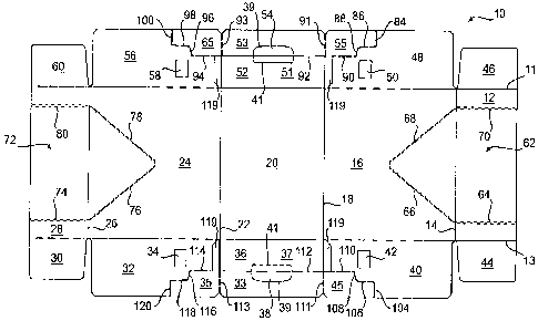
Fig. 1 illustrates a blank 10 that can be formed into a carton (Figs. 6-9), in
accordance with the exemplary embodiment of the present invention. Referring
to the
blank 10 of Fig. I in greater detail, it includes a first top panel 12
connected to a side
panel 16 by a fold line 14. The side panel 16 is connected to a bottom panel
20 at a
fold line 18. The bottom panel 20 is connected to a side panel 24 by a fold
line 22.
The side panel 24 is connected to a second top panel 28 by a fold line 26. The
blank
also includes one or more end flaps respectively at a peripheral portions of
the
panels 12, 16, 20, 24, 28, and in Fig. I the end flaps are respectively
foldably
connected to the panels by fold lines 11, 13 that extend between the ends of
the blank
10. At least some of the end flaps are optional. More specifically and as
shown in
Fig. 1, top end flaps 30, 60 are foldably attached to the opposite ends of the
second
top panel 28, end flaps 32, 56 are foldably connected to opposite ends of the
side
panel 24, bottom end flaps 36, 52 are foldably attached to opposite ends of
the bottom
panel 20, side end flaps 40, 48 are foldably attached to opposite ends of the
side panel
16, and top end flaps 44, 46 are foldably attached to opposite ends of the
first top
panel 12.
5
CA 02637660 2008-07-17
WO 2007/087342 PCT/US2007/001872
Pivotably attached closure flaps 38, 54 are respectively formed in the bottom
end flaps 36, 52 for closing / opening respective handle openings. The closure
flaps
38, 54 can be characterized as being optional, because they could be omitted
so that
the handle openings that are closed by the closure flaps are not closed by
closure flaps.
For example, the closure flap 54 is omitted in Figs. 2 and 3 so that its
associated
handle opening is seen. Each of the closure flaps 38, 54 can be defined, for
example,
by tear line(s) and/or slit(s) that extend between opposite ends of a fold
line, so that
the closure flap can be pivoted (e.g., folded) at its fold line. For example
and as
shown in Fig 1, each of the closure flaps 38, 54 is defined by a fold line 41,
and a
generally U-shaped slit or tear line 39 that extends between opposite ends of
the fold
line 41. Typically, the closure flaps 38, 54 will be configured so that they
are
manually deployed in a manner that cushions a user's grip on the handles of
the carton
erected from the blank 10, as will be discussed in greater detail below.
Differently
configured closure flaps 38, 54 and handle openings are within the scope of
the
present invention. For example and alternatively, each closure flap 38, 54 can
be in
the form of two or more closure flaps.
Glue locators are schematically designated as rectangles identified by
numerals 34, 42, 50, and 58 on the side end flaps 32, 40, 48, 56, although
differently
shaped glue locators can be used. Very generally described, each glue locator
34, 42,
50, 58 can be characterized as a target area for receiving adhesive material.
More
specifically and in accordance with one example, each glue locator can be
characterized as providing a "50% glue location site", although this
percentage can
vary with 50% being provided as exemplary only. In one example, each glue
locator
34, 42, 50, 58 can be cut 50% around its perimeter, although this percentage
can also
vary as desired, to allow top layer(s) of the paperboard at the glue locators
34, 42, 50,
58 to separate and be removed with the adhesive material adhered thereto, as
will be
discussed in greater detail below. In one specific example, the glue locators
34, 42,
50, 58 can be defined by (e.g., circumscribed by) kiss-cuts that extends
through about
50%, or another effective amount, of the thickness of the blank 10, so a
partial
thickness of the blank at the glue locators tears from the end flaps 32, 40,
48, 56 and
remains with adhesive material adhered thereto, as will be discussed in
greater detail
6
CA 02637660 2008-07-17
WO 2007/087342 PCT/US2007/001872
below. As also discussed in greater detail below, the glue locators 34, 42,
50, 58 can
be omitted or replaced with other features.
Fig. 1 also shows optional opening features 62 and 72 that can be at least
partially torn away from the carton erected from the blank 10, to provide
dispenser
openings through which contents can be removed from the interior of the
carton. In
general, the opening feature 62 is defined by one or more tear lines, which
can be
continuous or discontinuous. More specifically, the opening feature 62 can be
characterized as being partially defined by tear lines 64, 70 that are in the
top panel
12, and are shown as being substantially parallel to the fold lines 11, 13.
The opening
feature 62 can be further characterized as being defined by tear lines 66, 68
that are
located in the side panel 16 and extend obliquely / convergently from the tear
lines 64,
70 in the top panel 12. The tear lines 66 and 68 respectively intersect with
the tear
lines 64 and 70 at the fold line 14. The tear lines 66 and 68 extend
diagonally and
meet each other in a central portion of the side panel 16. Additional opening
features,
such as finger flaps or other features can be included to assist in the
separation of the
opening feature 62 from the blank 10 or carton formed therefrom, with such
additional
opening features typically being included somewhere along one of the tear
lines such
as adjacent the intersection of the tear lines 66 and 68.
The opening feature 72 is shown in Fig. 1 as being substantially similar to
(e.g., a mirror image of) the opening feature 62. The opening feature 72 is
defined by
one or more tear lines, which can be.continuous or discontinuous. More
specifically,
the opening feature 72 can be characterized as including tear lines 74, 80
that extend
in the top panel 28 and are parallel to the fold lines 11, 13. The opening
feature 72
can be further characterized as being defined by tear lines 76, 78 that are
located in the
side panel 24 and extend obliquely / convergently from the tear lines 74, 80
that
extend in the top panel 28. The tear lines 76 and 78 respectively intersect
the tear
lines 74 and 80 at the fold line 26. The tear lines 76 and 78 extend in a
generally
diagonal direction to meet each other in a central portion of the side panel
24.
Additional opening features, such as finger flaps, can be included with the
opening
feature 72, such as at the intersection of the tear lines 76 and 78.
7
CA 02637660 2008-07-17
WO 2007/087342 PCT/US2007/001872
In accordance with the exemplary embodiment of the present invention, the
carton erected from the blank 10 includes reinforced handle flaps 82, 102
(Figs. 3-9)
that include reinforcement features for increasing the strength of the handle
flaps or
areas adjacent the handle flaps. The reinforced handle flaps 82, 102 include
several
reinforcement features that are included in blank 10 and that can be folded
upon one
another during the manufacturing process to increase the strength of the
handles.
As can be understood with reference to Figs. 2 and 3, the reinforced handle
flap 82 includes a handle panel 53 that is a portion of the end flap 52, or is
an
additional segment of the end flap 52. More specifically and is shown in Figs.
I and
2, the end flap 52 can be characterized as including an intermediate portion
51 that is
foldably connected to the bottom panel 20 at the fold line 11, and foldably
connected
to the handle panel 53 at a fold line 92. As shown in Fig. 1, the fold line 92
extends
across the closure flap 54. A handle reinforcement portion 55 is defined by
slits
and/or tear lines such as tear lines 84, 86, 88, and 90 that extend in the
side end flap
48, and another tear line or fold line 91 that foldably connects the
reinforcement
portion 55 to the handle panel 53. The tear lines 86 and 88 define a profile
that is
substantially similar to the profile of a corresponding portion of the closure
flap 54 I
handle opening that is closed by the closure flap 54. Therefore, when the
reinforcement portion 55 is separated from (e.g., struck from) the side end
flap 48
along the tear lines 84, 86, 88, 90, and folded (e.g., pivoted) about the fold
line 91
onto the handle panel 53, the edges resulting from the tearing along the tear
lines 86
and 88 substantially extend along and are shaped substantially like adjacent
edges of
the handle opening associated with the closure flap 54. As shown in Fig. 3,
the side
end flap 48 defines an opening at least partially resulting from the
reinforcement
portion 55 having been struck from the side end flap 48.
Similarly, a reinforcement panel 65 is defined by tear lines 94, 96, 98, 100,
which are in the end flap 56, and a tear line or fold line 93. The tear lines
96 and 98
define a profile that is substantially similar to the profile of a
corresponding portion of
the closure flap 54 / handle opening that is closed by the closure flap 54.
Therefore,
when the reinforcement panel 65 is separated from (e.g., struck from) the side
end flap
56 along the tear lines 94, 96, 98, 100, and folded about the fold line 93,
the edges
8
CA 02637660 2008-07-17
WO 2007/087342 PCT/US2007/001872
resulting from the tearing along the tear lines 96 and 98 substantially extend
along and
are shaped substantially like adjacent edges of the handle opening associated
with the
closure flap 54. As shown in Fig. 3, the side end flap 56 defines an opening
at least
partially resulting from the reinforcement portion 65 having been struck from
the side
end flap 56.
Similarly, features for forming the reinforced handle flap 102 (Figs. 4-9) are
shown in Fig. 1, and the reinforced handle flap 102 is substantially similar
to the
reinforced handle flap 82. For example, a fold line 112 in the bottom end flap
36
demarcates a handle panel 33 of the bottom end flap 36. The handle panel 33
can be
characterized as being a part of the bottom end flap 36, and/or the handle
panel 33 can
be characterized as being foldably connected to the bottom end flap 36 by the
fold line
112, and/or the handle panel 33 can be characterized as being foldably
connected to an
intermediate portion 37 of the bottom end flap by the fold line 112. As shown
in Fig.
1, the fold line 112 extends across the closure flap 38, although other
arrangements
can be suitable. For example, the fold lines 112, 92 may be omitted, such as
from the
closure flaps 38, 54.
Tear lines 104, 106, 108, and 110, together with a tear line or fold line 111,
define a reinforcement panel 45 that is shown in the blank 10 as a segment of
end flap
40. Detachment of the reinforcement portion 45 along the tear lines 104, 106,
108,
and 110 (e.g., striking of the reinforcement portion 45 from the side end flap
40)
allows the reinforcement portion 45 to be pivoted (e.g., folded) about the
fold line
111, so that the reinforcement portion 45 reinforces the handle panel 33. The
tear
lines 106 and 108 substantially correspond in shape to the outline of a
portion of the
closure flap 38 and/or the handle opening associated with the closure flap 38.
Tear lines 114, 116, 118, and 120, together with a tear line or fold line 113,
define a reinforcement panel 35 that is shown in Fig. 1 as being a segment of
the side
end flap 32. Detachment along the tear lines 114, 116, 118, and 120 (e.g.,
striking of
the reinforcement portion 35 from the side end flap 32) allows the
reinforcement panel
35 to be folded about the fold line 113 to overlie the handle panel 33. In
this
overlying configuration, the edges resulting from tearing along the tear lines
116 and
118 have a profile that follows along and substantially corresponds to the
profile of a
9
CA 02637660 2008-07-17
WO 2007/087342 PCT/US2007/001872
corresponding portion of the closure flap 38 / associated handle opening,
similar to as
was discussed above regarding tear lines 96 and 98 in reference to the closure
flap 54.
Optionally, cut-outs / openings 119 can respectively be adjacent to, and
partially
define the shape, each of, the reinforcement panels 35, 45, 55, 65.
In accordance with the exemplary embodiment of the present invention, after
the blank 10 has been formed, a forming or other machine detaches (e.g.,
strikes) the
reinforcement panels 35, 45, 55, 65 along their respective tear lines and
pivots them to
create reinforcement. The reinforcement panels 35 and 45 can be folded over
and
adhered to the handle panel 33 to provide reinforcement thereto, and the
reinforcement portions 55 and 65 can be folded onto and adhered to the handle
panel
53 to provide reinforcement thereto, to respectively form the reinforced
handle flaps
82, 102. Typically, the reinforced handle flaps 82, 102 will be formed in the
blanks
prior to (e.g., immediately prior to or a long time prior to) erecting the
blanks into
cartons. Accordingly and in accordance with one aspect of the present
invention, a
blank that includes formed handle flaps 82, 102 can still be referred to as a
blank.
In accordance with an alternative embodiment of the present invention, the
handle flaps 82, 102 are not reinforced. In this case, they can respectively
consist
essentially of the handle panels 53, 33
An acceptable method for erecting a carton from a blank, after the reinforced
handle flaps 82, 102 have been formed in the blank, is described in the
following, in
accordance with the exemplary embodiment of the present invention. The blank
is
folded, such as along fold lines 18 and 26, so that there is an overlapping
arrangement
between portions of the top panels 12, 28, and the overlapped portions of the
top
panels 12, 28 are secured together by adhesive material or other means to form
a
sleeve. Then, the sleeve is opened by folding along the fold lines 14, 18, 22,
26, so
that the panels 12, 16, 20, 24, 28 extend around the interior of the open
sleeve / carton.
Cans C or other articles can be inserted into the interior of the open sleeve.
The
opposite ends of the sleeve are respectively closed with the end flaps 30, 32,
36, 40,
44, 46, 48, 52, 56, 50, which can be respectively secured to one another with
adhesive
material or other attachment mechanisms.
CA 02637660 2008-07-17
WO 2007/087342 PCT/US2007/001872
For example, Fig. 4 shows a partially open carton formed from the blank 10,
with cylindrical beverage containers C loaded therein, although the invention
is not
limited to such containers C or contents. In Fig. 4, the carton is housing two
levels of
containers C separated by a divider pad 122, which can be conventional. The
end
illustrated in Fig. 4 is partially closed by folding the side end flaps 32, 40
inwardly, for
example so that they abut the downwardly extending flap of the optional
divider pad
122. The upper end flaps 30, 40 are folded downwardly and respectively
securely
adhered to the closed side end flaps 32, 40. The bottom end flap 36 with the
reinforced handle 102 is folded inwardly so that the intermediate portion 37
of the
bottom end flap 36 abuts lower portions of the side end flaps 32, 40, and the
reinforcement panels 35, 45 of the reinforced handle 102 also abut the side
end flaps
32, 40. The intermediate portion 37 of the bottom end flap 36 is securely
adhered to
the side end flaps 32, 40, such as by way of adhesive material interposed
between the
intermediate portion 37 and the side end flaps 32, 40. The reinforcement
panels 35,
45 of the reinforced handle 102 are releasably adhered to the side end flaps
32, 40,
such as by way of adhesive material interposed between the reinforcement
panels 35,
45 and the side end flaps 32, 40.
Referring to Fig. 5, the releasable adhesion between the reinforcement panels
35, 45 of the reinforced handle 102 and the side end flaps 32, 40 can be
provided by
way of the glue locators 34, 42. In accordance with the exemplary embodiment
of the
present invention, the reinforcement panels 35, 45 of the reinforced handle
102 are
adhered to the side end flaps 32, 40 solely at the glue locators 34, 42, so
that this
adhesion is releasable. For example, the glue locators 34, 42 can be cut
(e.g., kiss-cut,
or otherwise cut) so that at least portions of the glue locators 34, 42 (e.g.,
top layer(s)
of the paperboard, or the like) can separate from the side end flaps 32, 40
when the
adhesive material that is adhered to the glue locators 34, 42 is pulled (e.g.,
pivoted)
away from the side end flaps 32, 40, as will be discussed in greater detail
below.
The other end of the carton is closed in a manner like that described above.
That is and in accordance with the exemplary embodiment of the present
invention,
the reinforced handles 82, 102 are respectively adhered to the side end flaps
32, 40,
48, 56 solely at the glue locators 34, 42, 50, 58, so that the reinforced
handles 82, 102
11
CA 02637660 2008-07-17
WO 2007/087342 PCT/US2007/001872
are respectively releasably attached (e.g., releasably adhered) to the side
end flaps 32,
40, 48, 56. Alternatively, the reinforced handles 82, 102 are respectively
releasably
attached to the side end flaps 32, 40, 48, 56 by way of any other mechanism
(e.g., by
using a releasable adhesive, or by adhering to a release coating, or any
combination
thereof or by any other suitable mechanism) that is sufficient for allowing
the
functionalities described herein. As another alternative, all adhesion between
the
reinforced handles 82, 102 and the side end flaps 32, 40, 48, 56 may in some
situations be omitted.
Fig. 6 shows the fully erected, loaded and closed carton. Fig. 7 shows the
carton with the reinforced handle flap 102 having been partially detached. In
order to
partially detach the reinforced handle flap 102 / move it from its closed
position
shown in Fig. 6 to the open position shown in Fig. 7, the handle flap 102 is
pivoted
downwardly, such as along the fold line 112, or another line. The handle flap
102
detaches from the side end flaps 32, 40 at the glue locators 34, 42, such as
by way of
portions of the glue locators 34, 42 tearing away from the side end flaps 32,
40. For
example, remnants of the glue locators 34, 42 are designated by 34a, 34b, 42a
and 42b
in Fig. 7. As mentioned above, the handle flap 102 can be releasably adhered
to or
otherwise connected to the side end flaps 32, 40 by way of features other than
the glue
locators 34, 42, and in an alternative embodiment the direct connection
between the
handle flap 102 and the side end flaps 32, 40 may be completely omitted.
In accordance with the exemplary embodiment of the present invention, prior
to detachment of the handle flaps 82, 102, typically, the adhesion between the
intermediate portions 37, 51 of the bottom end flaps 36, 52 and the side end
flaps 32,
40, 48, 56 is more secure / stronger than the adhesion between the handle
flaps 82,
102 and the side end flaps 32, 40, 48, 56, so that the intermediate portions
37, 51 of
the bottom end flaps 36, 52 remain adhered to the side end flaps 32, 40, 48,
56, when
the handle flaps 82, 102 are detached from the side end flaps 32, 40, 48, 56.
Alternatively, the intermediate portions 37, 51 of the bottom end flaps 36, 52
can
detach from the side end flaps 32, 40, 48, 56 along with the handle flaps 82,
102, in
which case the fold lines 92, 112 may be omitted from the bottom end flaps 36,
52.
12
CA 02637660 2008-07-17
WO 2007/087342 PCT/US2007/001872
Fig. 8 shows the fully erected carton with the handle flaps 82, 102 having
been
detached / pivoted in opposite directions downwardly relative to the remainder
of the
carton, and the initial downwardly pivoting typically involves unadhering the
handle
flaps from the side end flaps 32, 40, 48, 56, as discussed above. Glue
locators
remnants 34b, 58b are shown in Fig. 8, although they are optional as discussed
above.
As shown in Fig. 9, a user's fingers have been inserted through the handle
openings to
facilitate lifting of the carton. In accordance with one acceptable example,
the user's
fingers can be inserted through the handle openings by manually pivoting the
closure
flaps 38, 54 inwardly to open the handle openings so that the inwardly pivoted
closure
flaps 38, 54 cushion the user's grip on the handle flaps 82, 102, although the
closure
flaps 38, 54 may be omitted or configured differently.
In accordance with the exemplary embodiment of the present invention, the
carton can be opened by at least partially tearing the opening feature 62
and/or the
opening feature 72 from the carton, such as by tearing along one or more of
the tear
lines that define the opening feature(s), although other methods and features
for
opening are also within the scope of the present invention.
In the drawing figures herewith, the handle flaps 82, 102 are located at a
lower
portion of the carton, namely at each bottom end flap 36, 52; however, the
present
invention is not limited to this arrangement or orientation. Accordingly, the
handle
flaps could be disposed at different elevational levels and locations. In
addition,
whereas the handles have been shown and described as being in the form of
flaps, the
flap-like functionality of the handle flaps may be omitted in some situations,
such that
the handles are stationary with respect to the remainder of the carton rather
than being
flaps for pivoting with respect to the remainder of the carton. Further, the
carton as
shown in the drawing figures can be oriented to rest on any side. When this
occurs,
the handles can be seen on the side panels, top and bottom panels, or any
combination
thereof. Further, the handle feature(s) could be created in only one end panel
in lieu
of both end panels as shown in the drawing figures, and other configurations
are
contemplated.
13
CA 02637660 2008-07-17
WO 2007/087342 PCT/US2007/001872
In the embodiment shown in the drawing figures, the carton is shown as
accommodating cans or other substantially cylindrical packaged articles or
products.
Other types of articles, such as bottles or boxes, however, can be
accommodated
within a package according to the present invention. The dimensions of the
blank also
may be altered, for example, to accommodate various products, articles, etc.
In accordance with the exemplary embodiment of the present invention, the
blanks can be formed from paperboard, corrugated cardboard or other materials
having properties suitable for at least generally enabling respective
functionalities
described above. Paperboard is typically of a caliper such that it is heavier
and more
rigid than ordinary paper, and corrugated cardboard is typically of a caliper
such that it
is heavier and more rigid than paperboard. Typically, at least the side of the
paperboard or cardboard that will be an exterior surface in the carton erected
therefrom will be coated with a clay coating, or the like. The clay coating
can be
printed over with product, advertising, price-coding, and other information or
images.
The blanks may then be coated with a varnish to protect any information
printed on
the blanks. The blanks may also be coated with, for example, a moisture
barrier layer,
on one or both sides. The blanks can also be laminated to or coated with one
or more
sheet-like materials.
In accordance with the exemplary embodiment of the present invention, a fold
line can be any at least somewhat line-like arranged, although not necessarily
straight,
form of weakening that facilitates folding therealong; and a tear line can be
any at
least somewhat line-like arranged, although not necessarily straight, form of
weakening that facilitates tearing therealong. More specifically, but not for
the
purpose of narrowing the scope of the present invention, conventional fold
lines
include: a crease, such as formed by folding; a score line, such as formed
with a blunt
scoring knife, or the like, which creates a crushed portion in the material
along the
desired line of weakness; a slit that extends partially into the material
along the
desired line of weakness, and/or a series of spaced apart slits that extend
partially into
and/or completely through the material along the desired line of weakness; or
various
combinations of these features. More specifically, but not for the purpose of
narrowing the scope of the present invention, conventional tear lines include:
a slit
14
CA 02637660 2008-07-17
WO 2007/087342 PCT/US2007/001872
that extends partially into the material along the desired line of weakness,
and/or a
series of spaced apart slits that extend partially into and/or completely
through the
material along the desired line of weakness, or various combinations of these
features.
As a more specific example, one type of conventional tear line is in the form
of a series of spaced apart slits that extend completely through the material,
with
adjacent slits being spaced apart slightly so that a nick (e.g., a small
somewhat
bridging-like piece of the material) is defined between the adjacent slits for
typically
temporarily connecting the material across the tear line. The nicks are broken
during
tearing along the tear line. The nicks typically are a relatively small
percentage of the
tear line, and alternatively the nicks can be omitted from or torn in a tear
line such that
the tear line is a continuous cut line. That is, it is within the scope of the
present
invention for each of the tear lines to be replaced with a continuous slit, or
the like.
In accordance with the exemplary embodiment of the present invention, both
fold lines and tear lines can be more generally referred to as lines of
disruption.
For purposes of illustration, the exemplary embodiment of the present
invention has been disclosed as a paperboard carton configured for containing
containers, such as cans, in its interior. It will be understood that while
the carton
illustrated in the drawing figures generally is shown as a certain sized
carton, the
present invention is not limited to any specific size or dimension. For
example, the
carton of the present invention would work satisfactorily if sized and shaped
to hold
articles of other configurations, including thinner, thicker, and/or more
irregularly
shaped articles. Features of the present invention can also be used in cartons
that
include various other features, including opening features that provide easy
access to
the articles, tilt features that position the articles and carton, additional
handle
features, multiple openings, other opening or handle features, etc. Further,
different
shaped cartons, including nonrectangular or non-square or non-parallelepiped
cartons
and hexagonal cartons, are also within the scope of the present invention.
Also for purposes of illustration, the exemplary embodiment of the present
invention has been shown with tear lines defining opening features opening
features
62, 72. However, the present invention is not limited to any specific opening
features,
or openings formed by the opening features. In addition and more generally,
the
CA 02637660 2008-07-17
WO 2007/087342 PCT/US2007/001872
disclosed opening features and associated dispenser openings can be
characterized as
being optional (i.e., they could be omitted), since the contents of the carton
(e.g.,
articles such as cans, bottles, or the like) could be accessed by other means,
such as by
opening the end flaps, by a pour spout, by differently configured opening
features or
other mechanisms.
It will be understood by those skilled in the art that while the present
invention
has been discussed above with reference to exemplary embodiments, various
additions, modifications and changes can be made thereto without departing
from the
spirit and scope of the invention as set forth in the following claims.
16