Note: Descriptions are shown in the official language in which they were submitted.
CA 02637930 2014-01-06
SELF-EXCITING, SELF-SENSING PIEZOELECTRIC CANTILEVER SENSOR
[0001]
TECHNICAL FIELD
[0002] The technical field generally relates to sensors, and more specifically
relates to
piezoelectric cantilever sensors and to detecting and measuring analytes
utilizing a piezoelectric
cantilever sensor.
BACKGROUND
[0003] Cantilever sensors can be broadly divided into two categories,
depending upon
dimensions of the sensor: micro-cantilevers and macro-cantilevers. Micro-
cantilever sensors can
be utilized in both static (bending) mode and dynamic (resonance) mode. In
static mode, the
deformation of the cantilever arm is measured to determine if an analyte
(substance under
analysis) is present. In dynamic mode, a resonance frequency is measured to
determine if an
analyte is present. Macro-cantilever sensors typically are not utilized in the
static mode because
- 1 -
CA 02637930 2008-07-21
WO 2007/087328 PCT/US2007/001835
bending of the cantilever arm is often limited. Macro-cantilever sensors can
be utilized under
liquid immersion conditions or in a gas or vacuum. Typically, greater
sensitivity is achievable
when a cantilever sensor is utilized in a gas/vacuum than in a liquid. Liquid
dampening tends to
adversely affect sensitivity. However, Measuring analytes in liquid medium has
many practical
applications.
[0004] One type of known micro-cantilever sensor is a silicon-based micro-
cantilever
sensor. A typical silicon-based micro-cantilever sensor comprises a micro-
cantilever that acts as
a resonator. The micro-cantilever is driven by an external actuator at the
base of the micro-
cantilever to generate vibrations in the resonator. Typically, the vibrations
are detected by an
external optical detector. One disadvantage of typical silicon-based micro-
cantilevers is the
complex external optical components required for detection. Further, optical
detection means
disadvantageously limit application of the micro-cantilever sensor to
optically clear samples.
Another disadvantage is the weight and complexity added to the sensor due to
the external
actuator. Yet another disadvantage is that the external actuator can be
located only at the base of
the micro-cantilever, which limits its effectiveness in driving the
cantilever's vibration. A
further disadvantage of silicon-based micro-cantilever sensors is that they
are mechanically
fragile. Thus, silicon-based micro-cantilever sensors can not be used in high
liquid flow rate
environments. Further, typical silicon-based micro-cantilever sensors lose
detection sensitivity
in liquid media due to viscous damping.
[0005] Another type of known cantilever sensor is a quartz-based piezoelectric
cantilever sensor. Quartz is a weak piezoelectric, and thus, much like silicon-
based cantilever
sensors, quartz-based piezoelectric cantilever sensors lose detection
sensitivity in liquid media
due to viscous damping. Further, the detection sensitivity of quartz-based
sensors is limited by
the planar geometry of the sensor.
[0006] Conventional piezoelectric cantilevers are known to be fabricated with
a
piezoelectric layer attached to a non-piezoelectric layer over part or the
entire surface of the
piezoelectric layer. In some conventional piezoelectric cantilevers, the
piezoelectric layer is
fixed at one end so that when the piezoelectric material is excited, the non-
piezoelectric layer
flexes to accommodate the strain caused in the piezoelectric material. When
the frequency of
excitation is the same as the natural frequency of the underlying mechanical
structure, resonance
occurs. This type of piezoelectric cantilever sensor is known to operate at
frequencies lower than
about 100 kHz at millimeter size. Currently, higher frequencies are obtainable
only by making
- 2 -
CA 02637930 2008-07-21
WO 2007/087328 PCT/US2007/001835
the cantilever sensor very short (less than 1.0 mm in length), very narrow
(less than 0.1 mm in
width), and very thin (less than 100 microns in thickness). However, reducing
the dimensions of
the cantilever sensor, particularly the width, thusly, makes the cantilever
senor less usable in a
liquid medium due to viscous damping. Damping increases inversely with square
of cantilever
width.
SUMMARY
[0007] A self-exciting and self-sensing piezoelectric cantilever sensing
apparatus
includes a piezoelectric layer and a non-piezoelectric layer attached to the
piezoelectric layer
such that a distal end of the non-piezoelectric layer extends beyond a distal
end of the
piezoelectric layer or a distal end of the piezoelectric layer extends beyond
a distal end of the
non-piezoelectric layer. That is, the piezoelectric layer is coupled to the
non-piezoelectric layer
such that the piezoelectric layer and the non-piezoelectric layer are not
coextensive In various
configurations of the piezoelectric cantilever sensing apparatus, the
piezoelectric layer, the non-
piezoelectric layer, or both are anchored to at least one base. Electrodes are
operatively
associated with the piezoelectric layer. The self-exciting, self-sensing
piezoelectric cantilever
sensor is utilized to sense mass change. To determine the mass of an analyte
on the sensing
apparatus, the resonance frequency of the mechanical member of the cantilever
sensor is
measured. The measured resonance frequency is compared with a baseline
resonance frequency
to determine a difference in frequency. The difference in frequency is
indicative of a mass of an
analyte on the sensing apparatus.
=
BRIEF DESCRIPTION OF THE DRAWINGS
[0008] The foregoing summary, as well as the following detailed description,
is better
understood when read in conjunction with the appended drawings. For the
purpose of
illustrating a self-exciting, self-sensing piezoelectric Cantilever sensor,
there is shown in the
drawings exemplary constructions thereof; however, a self-exciting, self-
sensing piezoelectric
cantilever sensor is not limited to the specific methods and instrumentalities
disclosed.
[0009] Figure 1 is an illustration of an example configuration of a self-
exciting, self-
sensing piezoelectric cantilever sensor.
=
- 3 -
CA 02637930 2008-07-21
WO 2007/087328 PCT/US2007/001835
[0010] Figure 2 is a cross-sectional view of an example self-exciting, self-
sensing
piezoelectric cantilever sensor depicting electrode placement regions for
electrodes operationally
associated with the piezoelectric layer.
[0011] Figure 3 is a cross-sectional view of an example self-exciting, self-
sensing
piezoelectric cantilever sensor showing depicting example electrode placement
within a base
portion of the self-exciting, self-sensing piezoelectric cantilever sensor.
[0012] Figure 4 is a cross-sectional view of an example self-exciting, self-
sensing
piezoelectric cantilever sensor showing depicting example electrode placement
not within a base
portion of the self-exciting, self-sensing piezoelectric cantilever sensor.
[0013] Figure 5 is an illustration of an example configuration of a self-
exciting, self-
sensing piezoelectric cantilever sensor wherein the distal end of the
piezoelectric layer is flush
with the distal end of the non-piezoelectric layer.
[0014] Figure 6 is an illustration of an example configuration of a self-
exciting, self-
sensing piezoelectric cantilever sensor wherein the distal end of the
piezoelectric layer extends
beyond the distal end of the non-piezoelectric layer and the proximate end of
the piezoelectric
layer extends beyond the proximate end of the non-piezoelectric layer.
=
[0015] Figure 7 is an illustration of an example configuration of a self-
exciting, self-
sensing piezoelectric cantilever sensor having two base portions.
[0016] Figure 8 is an illustration of another example configuration of a self-
exciting,
self-sensing piezoelectric cantilever sensor, wherein the piezoelectric layer
is not attached to
either base portion.
[0017] Figure 9 is an illustration of an example configuration of a self-
exciting, self-
sensing piezoelectric cantilever sensor having the piezoelectric layer
anchored at two ends.
[0018] Figure 10 is an illustration of an example configuration of a self-
exciting, self-
sensing piezoelectric cantilever sensor wherein the piezoelectric layer
comprises two portions,
one of which is anchored.
-4-
CA 02637930 2008-07-21
WO 2007/087328 PCT/US2007/001835
[0019] Figure 11 is another illustration of an example configuration of a self-
exciting,
self-sensing piezoelectric cantilever sensor wherein the piezoelectric layer
comprises two
portions, one of which is anchored. ,
[0020] Figure 12 is an illustration of an example configuration of a self-
exciting, self-
sensing piezoelectric cantilever sensor wherein the piezoelectric layer
comprises two portions,
neither which is anchored.
[0021] Figure 13 is an illustration of an example configuration of a self-
exciting, self-
sensing piezoelectric cantilever sensor having an anchored non-piezoelectric
portion and a non-
anchored piezoelectric portion.
[0022] Figure 14 is an illustration of an example configuration of a self-
exciting, self-
sensing piezoelectric cantilever sensor, wherein the non-piezoelectric layer
is not attached to
either base portion.
[0023] Figure 15 is illustration of another example configuration of a self-
exciting, self-
sensing piezoelectric cantilever sensor wherein the piezoelectric portion has
a different width
than the piezoelectric portion.
[0024] Figure 16 is an illustration of an example configuration of a self-
exciting, self-
sensing piezoelectric cantilever sensor comprising a piezoelectric layer and a
non-piezoelectric
layer, wherein the width, of the piezoelectric layer is less than the width of
the non-piezoelectric
layer 16, and the distal end of the piezoelectric layer extends beyond the
distal end of the non-
piezoelectric layer and the proximate end of the piezoelectric layer extends
beyond the proximate
end of the non-piezoelectric layer.
[0025] Figure 17 is a flow diagram of an example process for detecting an
analyte
utilizing the self-exciting, self-sensing piezoelectric cantilever sensor.
[0026] Figure 18 is a plot of an example resonance spectrum of the
configuration of the
self-exciting, self-sensing piezoelectric cantilever sensor depicted in Figure
1, operated in air.
DETAILED DESCRIPTION OF ILLUSTRATIVE EMBODIMENTS
[0027] A self-exciting, self-sensing piezoelectric cantilever sensor as
described herein
provides the ability to detect and measure extremely small amounts of an
analyte. The self-
- 5 -
CA 02637930 2008-07-21
WO 2007/087328 PCT/US2007/001835
exciting, self-sensing piezoelectric cantilever sensor can be utilized to
detect and measure an
analyte immersed in a liquid and an analyte contained in a gas or vacuum. In
various example
configurations, the self-exciting, self-sensing piezoelectric cantilever
sensor comprises at least
one piezoelectric layer and at least one non-piezoelectric layer, wherein the
piezoelectric layer is
coupled to the non-piezoelectric layer such that the piezoelectric layer and
the non-piezoelectric
layer are not coextensive. The piezoelectric layer, the non-piezoelectric
layer, or both can be
coupled to at least one base. The piezoelectric layer and the non-
piezoelectric layer can be of
varying widths, lengths, and thicknesses.
[0028] The self-exciting, self-sensing piezoelectric cantilever sensor is
utilizable to
determine the mass of an analyte accumulated thereon. In an example
embodiment, a portion of
the self-exciting, self-sensing piezoelectric cantilever sensor is placed in a
medium (e.g., liquid,
gas, vacuum). While in the medium, a resonance frequency of the self-exciting,
self-sensing
piezoelectric cantilever sensor is measured and compared to a baseline
resonance frequency.
The difference in the measured resonance frequency and the baseline resonance
frequency is
indicative of an amount of mass of analyte accumulated (e.g., bound, adsorbed,
absorbed) on the
self-exciting, self-sensing piezoelectric cantilever sensor.
[0029] Analytes can be directly or indirectly bound to the surface of the non-
piezoelectric portion of the self-exciting, self-sensing piezoelectric
cantilever sensor. Binding of
an analyte to the non-piezoelectric portion of the self-exciting, self-sensing
piezoelectric
cantilever sensor results in a change in mass of the self-exciting, self-
sensing piezoelectric
cantilever sensor, a change in stiffness of the self-exciting, self-sensing
piezoelectric cantilever
sensor, or a combination thereof. The changes in mass and/or stiffness are
measurable as
changes in resonance frequency, and can be monitored and measured by an
appropriate analysis
device, such as an operational amplifier, an impedance analyzer, a network
analyzer, an
oscillator circuit, or the like, for example. Resonance frequency changes,
wherein at least a
portion of the self-exciting, self-sensing piezoelectric cantilever sensor is
immersed in a liquid,
are detectable and measurable. Resonance frequency changes, wherein at least a
portion of the
self-exciting, self-sensing piezoelectric cantilever sensor is immersed in a
gas or a vacuum, also
are detectable and measurable.
[0030] The self-exciting, self-sensing piezoelectric cantilever sensor is
operateable at
high frequencies, such as, on the order of 0.1 MHz. to 6 MHz, for example. At
these high
frequencies, a Q factor (the ratio of the resonance peak frequency relative to
the resonance peak
-6-
CA 02637930 2008-07-21
WO 2007/087328 PCT/US2007/001835
width at half peak height), on the order of 10 to 100, under liquid immersion
is obtainable. The
self-exciting, self-sensing piezoelectric cantilever sensor is operateable at
relative high
frequencies in liquid media, gas media, and a vacuum. The self-exciting, self-
sensing
piezoelectric cantilever sensor thus provides extreme sensitivity to mass
changes. The self-
exciting, self-sensing piezoelectric cantilever sensor is especially suitable
for analytes that are
present at very low concentrations in media such as in body fluids, water, and
food materials, for
example.
[0031] The self-exciting, self-sensing piezoelectric cantilever sensor
described herein
provides the ability to detect changes in mass accumulated thereon as small as
100 attogram/Hz
(100x10-18 grams/Hertz) or less when immersed in a liquid media. Thus, with
respect to
detecting changes in mass, the self-exciting, self-sensing piezoelectric
cantilever sensor is
approximately 1 million times more sensitive than a quartz crystal micro-
cantilever sensor,
approximate 100,000 times more sensitive than standard analytical instruments,
and about
10,000 times more sensitive than conventional, three-layer piezoelectric
cantilever designs.
[0032] The self-exciting, self-sensing piezoelectric cantilever sensor permits
detection
of extremely small concentrations of analyte that bind to the non-
piezoelectric portion thereof.
Utilizing the self-exciting, self-sensing piezoelectric cantilever sensor,
pathogens and proteins
are detectable at concentrations as low as a few pathogens/mL and, for
proteins of average size
(60 kilo-Daltons, kDa), at less than 1 pathogen/mL. Furthermore, any analyte
that binds to an
organic or inorganic functional group on the non-piezoelectric portion is
detectable. The self-
exciting, self-sensing piezoelectric cantilever sensor is operable in media
having relatively high
flow rates. The piezoelectric cantilevers sensors is operable in media having
flow rates of 0.5 to
10.0 mL/minute, which is approximately 1000 times the flow rate used
successfully with known
bending mode micro-cantilevers.
[0033] Various example applications of the piezoelectric cantilever include
the
detection of bioterrorism agents, such as Bacillus anthracis, the detection of
food-borne
pathogens, such as E. coli, the detection of pathogens in food and water, the
detection of certain
cell types in body fluids (e.g., circulating tumor cells), the detection of
biomarkers in body fluids
(e.g., proteins that mark specific pathophysiology- alpha-fetoprotein, beta-2-
microglobulin,
bladder tumor antigen, breast cancer marker CA-15-3, and other CAs (cancer
antigens),
calcitonin, carcinoembryonic antigen, and others), the detection of markers of
explosives such as
trinitrotoluene, the presence of dinitrotoluene, and the detection of airborne
and waterborne
- 7 -
CA 02637930 2008-07-21
WO 2007/087328 PCT/US2007/001835
toxins. The self-exciting, self-sensing piezoelectric cantilever sensor also
can be used for the
detection of biological entities at picogram levels, and for the detection of
protein-protein
interactions, both steady state and kinetic.
[0034] Pathogens, such as E-coli for example, are detectable utilizing the
self-exciting,
self-sensing piezoelectric cantilever sensor. Detection of a model protein,
lipoprotein, DNA,
and/or RNA at a concentration 1.0 femtogram per mL (10-15 grains) and
pathogens at 1
pathogen/mL, respectively is achievable by measuring directly in liquid using
the self-exciting,
self-sensing piezoelectric cantilever sensor immobilized with antibodies
specific to the target
analyte at a frequency of about 1 to 2 MHz. The self-exciting, self-sensing
piezoelectric
cantilever sensor is capable of detecting a target analyte without false
positives or negatives even
when contaminating entities are present. The self-exciting, self-sensing
piezoelectric cantilever
sensor described herein is particularly advantageous when utilized with a raw
sample, and no
preparation, concentrating step, and/or enrichment of any type. Detection of
an analyte utilizing
the self-exciting, self-sensing piezoelectric cantilever sensor can be
conducted directly in raw
samples under flow conditions, such as 0.5 to 10.0 mL/minute for example. If
clean samples are
available, such as in a laboratory environment, detection at 1 femtogram/mL is
achievable. This
sensitivity is approximately 100 times more sensitive than the sensitivity
associated with known
optical techniques.
[0035] As described below, the sensitivity of the self-exciting, self-sensing
piezoelectric cantilever sensor is due in part to the geometric design
thereof. The relative lengths
and widths of the piezoelectric and non-piezoelectric layers of the self-
exciting, self-sensing
piezoelectric cantilever sensor determine the sensitivity, and also the shape
of the peak of the
frequency spectrum provided by the self-exciting, self-sensing piezoelectric
cantilever sensor. -
As described in more detail below, the self-exciting, self-sensing
piezoelectric cantilever sensor
comprises a piezoelectric layer and a non-piezoelectric layer coupled together
such that a portion
of the piezoelectric layer extends beyond the non-piezoelectric layer, or a
portion of the non-
piezoelectric layer extends beyond the piezoelectric layer, or a combination
thereof. Thus, the
piezoelectric layer and the non-piezoelectric layer are not coextensive. That
is, the self-exciting,
self-sensing piezoelectric cantilever sensor is configured such that an entire
surface of the non-
piezoelectric layer is not coupled to an entire surface of the piezoelectric
layer.
[0036] The sensitivity of the self-exciting, self-sensing piezoelectric
cantilever sensor is
due in part to utilizing the piezoelectric layer of the cantilever sensor for
both actuation and
- 8 -
CA 02637930 2008-07-21
WO 2007/087328 PCT/US2007/001835
sensing and the electromechanical properties of the piezoelectric layer of the
self-exciting, self-
sensing piezoelectric cantilever sensor. At resonance, the oscillating
cantilever concentrates
stress in the piezoelectric layer toward a base portion of the self-exciting,
self-sensing
piezoelectric cantilever. This results in an amplified change in the resistive
component of the
piezoelectric layer, and a large shift in resonance frequency. Directing this
stress to a portion of
the piezoelectric layer having a low bending modulus (e.g., more flexible)
allows for exploitation
of the associated shift in resonance frequency to detect extremely small
changes in mass of the
self-exciting, self-sensing piezoelectric cantilever sensor. For example, if
both the piezoelectric
layer and the non-piezoelectric layer of a piezoelectric cantilever sensor are
anchored at the same
end (e.g., potted in epoxy), the sensor is less sensitive to changes in mass
because the bending
stress in the sensing piezoelectric layer proximal to the anchored end is
lower compared to the
case when only the piezoelectric layer is anchored. This is because the
bending modulus of the
two combined layers is higher than the case of anchoring the piezoelectric
layer only. Bending
modulus is the product of elastic modulus and moment of inertia about the
neutral axis. And,
moment of inertia is proportional to the cube power of thickness.
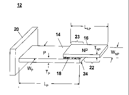
100371 Figure 1 is an illustration of a self-exciting, self-sensing
piezoelectric cantilever
sensor 12 comprising a piezoelectric portion 14 and a non-piezoelectric
portion 16. Piezoelectric
portions are labeled with an uppercase letter p ("P"), and non-piezoelectric
portions are labeled
with the uppercase letters np ("NP"). The self-exciting, self-sensing
piezoelectric cantilever
sensor 12 depicts an embodiment of an unanchored, overhang, self-exciting,
self-sensing
piezoelectric cantilever sensor. The self-exciting, self-sensing piezoelectric
cantilever sensor 12
is termed "unanchored" because the non-piezoelectric layer 16 is not attached
to the base portion
20. The self-exciting, self-sensing piezoelectric cantilever sensor 12 is
termed, "overhang"
because the non-piezoelectric layer 16 extends beyond the distal tip 24 of the
piezoelectric layer
14 to create an overhanging portion 22 of the non-piezoelectric layer 16. The
piezoelectric
portion 14 is coupled to the non-piezoelectric portion 16 via adhesive portion
18. The
piezoelectric portion 14 and the non-piezoelectric portion overlap at region
23. The adhesive
portion 18 is positioned between the overlapping portions of the piezoelectric
portion 14 and the
non-piezoelectric portion 16. The piezoelectric portion 14 is coupled to a
base portion 20.
[00381 The piezoelectric portion 14 can comprise any appropriate material such
as lead
zirconate titanate, lead magnesium niobate-lead titanate solid solutions,
strontium lead titanate,
quartz silica, piezoelectric ceramic lead zirconate and titanate
piezoceramic-polymer fiber
composites, or the like, for example. The non-piezoelectric portion 16 can
comprise any
-9-
CA 02637930 2008-07-21
WO 2007/087328 PCT/US2007/001835
appropriate material such as glass, ceramics, metals, polymers and composites
of one or more of
ceramics, and polymers, such as silicon dioxide, copper, stainless steel,
titanium, or the like, for
example.
100391 The self-exciting, self-sensing piezoelectric cantilever sensor can
comprise
portions having any appropriate combination of dimensions. Further, physical
dimensions can
be non-uniform. Thus, the piezoelectric layer and/or the non-piezoelectric
layer can be tapered.
For example, the length (e.g., Lp in Figure 1) of the piezoelectric portion
(e.g., piezoelectric
portion 14) can range from about 0.1 to about 10 mm. The length (e.g., 1.,Np
in Figure 1) of the
non-piezoelectric portion (e.g., non-piezoelectric portion 16) can range from
about 0.1 to about
mm. The overlap region (e.g., overlap region 23) can range from about 0.1 to
about 10 mm in
length. The width (e.g., W p in Figure 1) of the piezoelectric portion (e.g.,
piezoelectric portion
14), and the width (e.g., WNp in Figure 1) of the non-piezoelectric portion
(e.g., non-piezoelectric
portion 16), can range from about 0.1 mm to about 4.0 mm. The width (e.g., Wp
in Figure 1) of
the piezoelectric portion can differ from the width (e.g., WNp in Figure 1) of
the non-
piezoelectric portion as well. The thickness of the (e.g., Tp in Figure 1) of
the piezoelectric
portion (e.g., piezoelectric portion 14), and the thickness (e.g., TNp in
Figure 1) of the non-
piezoelectric portion (e.g., non-piezoelectric portion 16), can range from
about 0.1 mm to about
4.0 mm. The thickness (e.g., Tp in Figure 1) of the piezoelectric portion also
can differ from the
thickness (e.g., TNp in Figure 1) of the non-piezoelectric portion.
[0040] Figure 2 is a cross-sectional view of the self-exciting, self-sensing
piezoelectric
cantilever sensor 12 depicting electrode placement regions 26 for electrodes
operationally
associated with the piezoelectric portion 14. Electrodes can be placed at any
appropriate location
on the piezoelectric portion of the self-exciting, self-sensing piezoelectric
cantilever sensor as
indicated by brackets 26. For example, as shown in Figure 3, electrodes 28 can
be coupled to the
piezoelectric portion 14 within the base portion 20. Or, as depicted in Figure
4, electrodes 32
can be coupled to the piezoelectric portion 14 at any location not within the
base portion 20 and
not overlapped by the non-piezoelectric portion 16. Electrodes need not be
placed symmetrically
about the piezoelectric portion 14. In an example embodiment, one electrode
can be coupled to
the piezoelectric portion 14 within the base portion 20 and the other
electrode can be coupled to
the piezoelectric portion 14 not within the base portion 20. Electrodes, or
any appropriate means
(e.g., inductive means, wireless means), can be utilized to provide an
electrical signal to and
receive an electrical signal from the piezoelectric portion 14. In an example
embodiment,
electrodes can be coupled to the piezoelectric portion 14 via a bonding pad or
the like (depicted
-10-
CA 02637930 2008-07-21
WO 2007/087328 PCT/US2007/001835
as elements 30 in Figure 3 and elements 34 in Figure 4). Example bonding pads
can comprise
any appropriate material (e.g., gold, silicon oxide) capable of immobilization
of a receptor
material and/or an absorbent material appropriate for use in chemical sensing
or for bio-sensing.
[0041] Electrodes can be placed at any appropriate location. In an example
embodiment, electrodes are operatively located near a location of concentrated
stress in the
piezoelectric layer 14. As described above, the sensitivity of the self-
exciting, self-sensing
piezoelectric cantilever sensor is due in part to advantageously directing
(concentrating) the
stress in the piezoelectric layer 14 and placing electrodes proximate thereto.
The configurations
of the self-exciting, self-sensing piezoelectric cantilever sensor described
herein (and variants
thereof) tend to concentrate oscillation associated stress in the
piezoelectric layer 14. At
resonance, in some of the configurations of the self-exciting, self-sensing
piezoelectric cantilever
sensor, the oscillating cantilever concentrates stress in the piezoelectric
layer 14 toward the base
portion 20. This results in an amplified change in the resistive component of
the piezoelectric
layer 14, and a large shift in resonance frequency at the locations of high
stress. Directing this
stress to a portion of the piezoelectric layer 14 having a low bending modulus
(e.g., more
flexible) allows for exploitation of the associated shift in resonance
frequency to detect
extremely small changes in mass of the self-exciting, self-sensing
piezoelectric cantilever sensor.
Thus, in example configurations of the self-exciting, self-sensing
piezoelectric cantilever sensor,
the thickness of the piezoelectric layer 14 located near the base portion 20
is thinner than
portions of the piezoelectric layer 14 further away from the base portion 20.
This tends to
concentrate stress toward the thinner portion of the piezoelectric layer 14.
In example
configurations, electrodes are located at or near the locations of the
oscillation associated
concentrated stress near the base portion of the self-exciting, self-sensing
piezoelectric cantilever
sensor. In other example configurations of the self-exciting, self-sensing
piezoelectric cantilever
sensor electrodes are positioned proximate the location of concentrated stress
in the piezoelectric
layer regardless of the proximity of the concentrated stress to a base portion
of the self-exciting,
self-sensing piezoelectric cantilever sensor.
[0042] The self-exciting, self-sensing piezoelectric cantilever sensor can be
configured
in accordance with a plurality of configurations, some of which are depicted
in Figure 5 through
Figure 16. It is to be understood however, that the configurations depicted
herein do not
represent all possible configurations, but rather a representative sample of
configurations of the
self-exciting, self-sensing piezoelectric cantilever sensor. Figure 5 is an
illustration of an
example configuration 36 of an unanchored self-exciting, self-sensing
piezoelectric cantilever
-11-
CA 02637930 2008-07-21
WO 2007/087328 PCT/US2007/001835
sensor wherein the distal end 40 of the piezoelectric portion 14 is flush with
the distal end 38 of
the non-piezoelectric portion 16. The self-exciting, self-sensing
piezoelectric cantilever sensor
36 is termed "unanchored" because the non-piezoelectric portion 16 is not
attached to the base
portion 20. The piezoelectric portion 14 is coupled to the non-piezoelectric
portion 16 via
adhesive portion 18. The adhesive portion 18 is positioned between the
overlapping portions of
the piezoelectric portion 14 and the non-piezoelectric portion 16. The
piezoelectric portion 14 is
coupled to a base portion 20.
[0043] Figure 6 is an illustration of an example configuration 42 of an
unanchored self-
exciting, self-sensing piezoelectric cantilever sensor wherein the distal end
44 of the
piezoelectric portion 14 extends beyond the distal end 46 of the non-
piezoelectric portion 16 and
the proximate end 43 of the piezoelectric portion 14 extends beyond the
proximate end 45 of the
non-piezoelectric portion 16. The piezoelectric portion 14 is coupled to the
non-piezoelectric
portion 16 via adhesive portion 18. The adhesive portion 18 is positioned
between the
overlapping portions of the piezoelectric portion 14 and the non-piezoelectric
portion 16. The
piezoelectric portion 14 is coupled to the base portion 20.
[0044] The self-exciting, self-sensing piezoelectric cantilever sensor also
can be
configured to comprise multiple base portions. Example configurations of the
self-exciting, self-
sensing piezoelectric cantilever sensor comprising multiple base portions are
depicted in Figure 7
through Figure 14. Configuring the self-exciting, self-sensing piezoelectric
cantilever sensor to
comprise multiple base portions is not intuitive because the expectation of
one skilled in the art
would be that affixation of both ends of the self-exciting, self-sensing
piezoelectric cantilever
sensor would provide a poor response as a result of the restrictions of the
displacement of the
self-exciting, self-sensing piezoelectric cantilever sensor as a result of its
affixation to the
multiple base portions. For configurations of the self-exciting, self-sensing
piezoelectric
cantilever sensor comprising two base portions, in an example embodiment, the
stress of in the
piezoelectric portion is measured, rather than the displacement of the
piezoelectric portion.
Configuring the self-exciting, self-sensing piezoelectric cantilever sensor to
comprise two base
portions provides a stable and robust sensor that can perform under relatively
high media flow
conditions and provide excellent mass change sensitivity. Along with providing
a mechanically
robust self-exciting, self-sensing piezoelectric cantilever sensor that can
withstand a relatively
wide range of media flow conditions with minimal determination in performance,
configuring
the self-exciting, self-sensing piezoelectric cantilever sensor to comprise
two base portions
- 12 -
CA 02637930 2008-07-21
WO 2007/087328 PCT/US2007/001835
provides a fundamental frequency (e.g., greater than 100 kHz) that is three to
four times higher
than a cantilever sensor having a single base portion and of similar
dimensions.
[0045] Figure 7 is an illustration of an example configuration 48 of an
anchored self-
exciting, self-sensing piezoelectric cantilever sensor comprising two base
portions 20, 50. The
self-exciting, self-sensing piezoelectric cantilever sensor 48 is termed
"anchored" because the
non-piezoelectric portion 16 is attached to the base portion 20. In the
configuration depicted in
the self-exciting, self-sensing piezoelectric cantilever sensor 48, both the
proximate end 52 of the
piezoelectric portion 14 and the proximate end 54 of the non-piezoelectric
portion 16 are
attached to the base portion 20. The piezoelectric portion and the non-
piezoelectric portion can
be attached to the base portion via any appropriate means. The distal end 58
of the non-
piezoelectric portion 16 also is attached to the base portion 50. The distal
end 58 of the non-
piezoelectric portion 16 extends beyond the distal portion 56 of the
piezoelectric portion 14. The
piezoelectric portion 14 is coupled to the non-piezoelectric portion 16 via
adhesive portion 18.
The adhesive portion 18 is positioned between the overlapping portions of the
piezoelectric
portion 14 and the non-piezoelectric portion 16.
[0046] Figure 8 is an illustration of an example configuration 60 of an
anchored self-
exciting, self-sensing piezoelectric cantilever sensor comprising two base
portions 20, 50,
wherein the piezoelectric portion 14 is not attached to either base portion 20
or base portion 50.
In the configuration depicted in the self-exciting, self-sensing piezoelectric
cantilever sensor 60,
the proximate end 62 of the non-piezoelectric portion 16 is attached to the
base portion 20 and
the distal end 64 of the non-piezoelectric portion 16 is attached to the base
portion 50. The
proximate end 62 of the non-piezoelectric portion 16 extends beyond the
proximate end 66 of the
piezoelectric portion 14 and the distal end 64 of the non-piezoelectric
portion 16 extends beyond
the distal end 68 of the piezoelectric portion 14. The piezoelectric portion
14 is coupled to the
non-piezoelectric portion 16 via adhesive portion 18. The adhesive portion 18
is positioned
between the overlapping portions of the piezoelectric portion 14 and the non-
piezoelectric
portion 16.
[0047] Figure 9 is an illustration of an example configuration 70 of an
anchored self-
exciting, self-sensing piezoelectric cantilever sensor comprising two base
portions 20, 50,
comprising two piezoelectric portions 14, 72, and comprising two adhesive
portions 18, 74. In
the configuration depicted in the self-exciting, self-sensing piezoelectric
cantilever sensor 70, the
proximate end 76 of the piezoelectric portion 14 and the proximate end 78 of
the non-
- 13 -
CA 02637930 2008-07-21
WO 2007/087328 PCT/US2007/001835
piezoelectric portion 16 are attached to the base portion 20. The distal end
80 of the
piezoelectric portion 72 and the distal end 82 of the non-piezoelectric
portion 16 are attached to
the base portion 50. The proximate end 78 of the non-piezoelectric portion 16
extends beyond
the proximate end 86 of the piezoelectric portion 72. The distal end 82 of the
non-piezoelectric
portion 16 extends beyond the distal end 84 of the piezoelectric portion 14.
The distal end 84 of
the piezoelectric portion 14 and the proximate end 86 of the piezoelectric
portion 72 form a
space 88 therebetween. The piezoelectric portion 14 is coupled to the non-
piezoelectric portion
16 via adhesive portion 18. The piezoelectric portion 72 is coupled to the non-
piezoelectric
portion 16 via adhesive portion 74. The adhesive portions 18 and 74 are
positioned, respectively,
between the overlapping portions of the piezoelectric portion 14 and the non-
piezoelectric
portion 16, and the piezoelectric portion 72 and the non-piezoelectric portion
16.
[0048] In various alternate example configurations of the configuration 70
depicted in
Figure 9, only one of the piezoelectric portions 14, 72 is attached to a
respective base portion 20,
50. For example, in one example configuration as depicted in Figure 10, the
piezoelectric
portion 14 is attached to the base portion 20 and the piezoelectric portion 72
is not attached to the
base portion 50. In another example configuration, as depicted in Figure 11,
the piezoelectric
portion 72 is attached to the base portion 50 and the piezoelectric portion 14
is not attached to the
base portion 20. In yet another example configuration, as depicted in
Figure.12, neither the
piezoelectric portion 14 nor the piezoelectric portion 72 is attached to a
respective base portion
20, 50.. In the various example configurations in which a piezoelectric layer
comprises multiple
portions, electrodes can be attached to any appropriate piezoelectric portion
or portions. For
example, in the example configuration depicted in Figure 9, Figure 10, Figure
11, and Figure 12,
electrodes can be attached to piezoelectric portion 14, piezoelectric portion
72, or a combination
thereof.
[0049] Figure 13 is an illustration of an example configuration 90 of an
anchored self-
exciting, self-sensing piezoelectric cantilever sensor comprising two base
portions 20, 50,
wherein the piezoelectric portion 14 is attached to the base portion 20 and
the non-piezoelectric
portion 16 is attached to the base portion 50. The piezoelectric portion 14 is
coupled to the non-
piezoelectric portion 16 via adhesive portion 18. The adhesive portion 18 is
positioned between
the overlapping portions of the piezoelectric portion 14 and the non-
piezoelectric portion 16.
The distal end 98 of the non-piezoelectric portion 16 extends beyond the
distal end 96 of the
piezoelectric portion 14. The proximate end 92 of the piezoelectric portion 14
extends beyond
the proximate end 94 of the non-piezoelectric portion 16.
- 14 -
CA 02637930 2008-07-21
WO 2007/087328 PCT/US2007/001835
[0050] Figure 14 is an illustration of an example configuration 100 of an
anchored self-
exciting, self-sensing piezoelectric cantilever sensor comprising two base
portions 20, 50,
wherein the non-piezoelectric portion 16 is not attached to either base
portion 20 or base portion
50. In the configuration depicted in the self-exciting, self-sensing
piezoelectric cantilever sensor
100, the proximate end 102 of the piezoelectric portion 14 is attached to the
base portion 20 and
the distal end 104 of the piezoelectric portion 14 is attached to the base
portion 50. The
proximate end 102 of the piezoelectric portion 14 extends beyond the proximate
end 106 of the
non-piezoelectric portion 16 and the distal end 104 of the piezoelectric
portion 14 extends
beyond the distal end 108 of the non-piezoelectric portion 16. The
piezoelectric portion 14 is
coupled to the non-piezoelectric portion 16 via adhesive portion 18. The
adhesive portion 18 is
positioned between the overlapping portions of the piezoelectric portion 14
and the non-
piezoelectric portion 16.
[0051] Figure 15 is an illustration of an example configuration 110 of an
unanchored
self-exciting, self-sensing piezoelectric cantilever sensor comprising a
piezoelectric portion 14
and a non-piezoelectric portion 16, wherein the width, Wp, of the
piezoelectric portion is less
than the width, WNp, of the non-piezoelectric portion 16. The configuration
110 depicted in
Figure 15 is similar to the configuration 12 depicted in Figure 1, with the
exception that Wp is
less than WNp. According, the self-exciting, self-sensing piezoelectric
cantilever sensor 110
depicts arrembodiment of an unanchored, overhang, self-exciting, self-sensing
piezoelectric
cantilever sensor. The piezoelectric portion 14 is coupled to the non-
piezoelectric portion 16 via
adhesive portion (adhesive portion not shown in Figure 15). The adhesive
portion is positioned
between the overlapping portions of the piezoelectric portion 14 and the non-
piezoelectric
portion 16. The piezoelectric portion 14 is coupled to a base portion 20.
[0052] Figure 16 is an illustration of an example configuration 112 of an
unanchored
self-exciting, self-sensing piezoelectric cantilever sensor comprising a
piezoelectric portion 14
and a non-piezoelectric portion 16, wherein the width, Wp, of the
piezoelectric portion is less
than the width, WNp, of the non-piezoelectric portion 16, and wherein the
distal end 114 of the
piezoelectric portion 14 extends beyond the distal end 116 of the non-
piezoelectric portion 16
and the proximate end 118 of the piezoelectric portion 14 extends beyond the
proximate end 120
of the non-piezoelectric portion 16. The configuration 112 depicted in Figure
16 is similar to the
configuration 42 depicted in Figure 6, with the exception that Wp is less than
WNp. The
piezoelectric portion 14 is coupled to the non-piezoelectric portion 16 via
adhesive portion
(adhesive portion not shown in Figure 16). The adhesive portion is positioned
between the
- 15 -
CA 02637930 2008-07-21
WO 2007/087328 PCT/US2007/001835
overlapping portions of the piezoelectric portion 14 and the non-piezoelectric
portion 16. The
piezoelectric portion 14 is coupled to the base portion 20.
[0053] Figure 17 is a flow diagram of an example process for detecting an
analyte
utilizing the self-exciting, self-sensing piezoelectric cantilever sensor. The
self-exciting, self-
sensing piezoelectric cantilever sensor is provided at step 120. The self-
exciting, self-sensing
piezoelectric cantilever sensor can be configured in accordance with the
descriptions provided
above, or configured in accordance with any appropriate variant is thereof.
The self-exciting,
self-sensing piezoelectric cantilever sensor is prepared to receive an analyte
at step 122. In an .
example embodiment, an analyte attractor is applied to the non-piezoelectric
portion of the self-
exciting, self-sensing piezoelectric cantilever sensor. The attractor is
specific to an analyte.
Thus the attractor will attract a target analyte and not attract other
substances. For example, the
non-piezoelectric portion of the self-exciting, self-sensing piezoelectric
cantilever sensor can
comprise an attractor for attracting bioterrorism agents, such as Bacillus
anthracis, food-borne
pathogens, such as E. coli, pathogens in food and water, cell types in body
fluids (e.g.,
circulating tumor cells), biomarkers in body fluids (e.g., proteins that mark
specific
pathophysiology- alpha-fetoprotein, beta-2-microglobulin, bladder tumor
antigen, breast cancer
marker CA-15-3, and other CAs (cancer antigens), calcitonin, carcinoembryonic
antigen, and
others), markers of explosives such as trinitrotoluene, dinitrotoluene,
airborne and waterborne
toxins, biological entities, such as a protein, or a combination thereof, for
example.
100541 The self-exciting, self-sensing piezoelectric cantilever sensor is
exposed to a
medium at step 124. The medium can comprise any appropriate medium, such as a
liquid, a gas,
a combination of a liquid and a gas, or a vacuum, for example. The medium can
exhibit a wide
variety of flow conditions. If a target analyte is present in the medium, the
target analyte will
accumulate on the non-piezoelectric portion of the self-exciting, self-sensing
piezoelectric
cantilever sensor that has been treated with the attractor. As described
above, accumulation
(e.g., binding) of the target analyte on the non-piezoelectric portion of the
self-exciting, Self-
sensing piezoelectric cantilever sensor will result in a change in stiffness
of the self-exciting,
self-sensing piezoelectric cantilever sensor and/or an increase the mass of
the self-exciting, self-
sensing piezoelectric cantilever sensor, which will decrease the resonance
frequency of the self-
exciting, self-sensing piezoelectric cantilever sensor.
[0055] The resonance frequency of the self-exciting, self-sensing
piezoelectric
cantilever sensor is measure at step 126. The resonance frequency can be
measured by any
- 16 -
CA 02637930 2008-07-21
WO 2007/087328 PCT/US2007/001835
appropriate means, such as an operational amplifier, an impedance analyzer, a
network analyzer,
an oscillator circuit, or the like, for example. When the piezoelectric
material of the piezoelectric
portion of the self-exciting, self-sensing piezoelectric cantilever sensor is
excited, the non-
piezoelectric portion of the self-exciting, self-sensing piezoelectric
cantilever sensor flexes to
accommodate the strain caused in the piezoelectric material. When the
frequency of excitation is
the same as the natural frequency of the underlying mechanical structure,
resonance occurs.
[0056] The measured resonance frequency is compared to a baseline resonance
frequency at step 128. The baseline resonance frequency is the resonance
frequency of the self-
exciting, self-sensing piezoelectric cantilever sensor having no analyte
accumulated thereon. If a
difference in frequency (frequency shift) between the measured resonance
frequency and the
baseline resonance frequency is not measured (at step 130), it is determined,
at step 132, that no
analyte is detected. If a difference in frequency between the measured
resonance frequency and
the baseline resonance frequency is measured (at step 130), it is determined,
at step 134, that an
analyte is detected, i.e., an analyte is present in the medium. At step 136,
the amount of mass of
the analyte that has accumulated on the non-piezoelectric portion of the self-
exciting, self-
sensing piezoelectric cantilever sensor is determined in accordance with the
frequency shift
measured at step 130.
[0057] Various experiments have been conducted utilizing various
configurations of the
self-exciting, self-sensing piezoelectric cantilever sensor. Figure 18 is a
plot 137 of an example
resonance spectrum of the configuration 12 of the self-exciting, self-sensing
piezoelectric
cantilever sensor, depicted in Figure 1, operated in air. The width, Wp, and
the width, WNP, were
each approximately 2 mm. The plot 137 shows the phase angle (between the
excitation voltage
and the excitation current) versus excitation frequency, at an excitation
voltage of 100 mV. The
first resonance frequency mode 140 occurred approximately between 150 and 200
kHz and the
second resonance frequency mode 142 occurred between 250 and 300 kHz. The
resonance
spectrum shows higher order characteristic peaks at approximately 980 kHz,
2.90 MHz and 4.60
MHz.
[0058] Quality factors were determined as a ratio of the resonant frequency to
the peak
width at half the peak height. As a result, the quality factor is a measure of
the sharpness of the
resonant peaks. Experimentation has shown that the quality factor of the self-
exciting, self-
sensing piezoelectric cantilever sensor does not decrease significantly when
the sensor is placed
in different environments ranging from vacuum to liquid flow environments.
Also,
-17-
CA 02637930 2008-07-21
WO 2007/087328 PCT/US2007/001835
experimentation has shown that the Q values for the various configurations of
the self-exciting,
self-sensing piezoelectric cantilever sensor typically range between 10 and
70, depending upon
the respective frequency mode where the peak is detected. The various
configurations of the
self-exciting, self-sensing piezoelectric cantilever sensor, when used in
vacuum, air, and viscous
environments, including flows, typically did not have more than a 20%-35%
decrease in Q value.
This relatively small loss in the overall value of the quality factor reflects
the ability of the self-
exciting, self-sensing piezoelectric cantilever sensor to accurately detect
chemicals and various
biological items in viscous environments, including water and bloodstreams.
[0059] Experimentation has shown that the sensitivity of the self-exciting,
self-sensing
piezoelectric cantilever sensor is a function of the dimensions thereof.
Specific changes in the
geometry of the self-exciting, self-sensing piezoelectric cantilever sensor
enhanced the sensor's
mass change sensitivity, and thus, the sensor's response to the detection of
low concentration of
analyte. The resonance spectrum, a plot of phase angle versus excitation
frequency, in air,
showed dominant bending mode resonant peaks at 102 0.05, 970 0.05, and
1810 0.05 kHz,
respectively. By changing the geometry of the of the self-exciting, self-
sensing piezoelectric
cantilever sensor, the sensor's resonance characteristics were enhanced. The
corresponding
bending resonant modes occurred at higher frequencies and had larger phase
angles, suggesting
that resonant peaks of the self-exciting, self-sensing piezoelectric
cantilever sensor are more
sensitive and are less dampened.
[0060] In an example experiment, the mass change sensitivity of the self-
exciting, self-
sensing piezoelectric cantilever sensor was measured. A known mass of paraffm
wax was added
to a glass surface of the self-exciting, self-sensing piezoelectric cantilever
sensor and the change
in resonant frequency was used to compute the mass sensitivity, expressed in
g/Hz. Direct
measurement was made of the mass change sensitivity in liquid; as well as the
ratio of known
mass to the change in resonant frequency in liquid before and after mass was
added. The mass
sensitivity of the resonant mode investigated under liquid was determined to
be 1.5 x 10⁵ g/Hz.
- 18 -