Note: Descriptions are shown in the official language in which they were submitted.
CA 02637960 2008-07-15
TITLE: DIFFERENTIAL GENERATION POWER
DISTRIBUTION SYSTEM
BACKGROUND OF THE INVENTION
s (a) Field of the Invention
The present invention is related to a differential generation power
distribution system, and more particularly to one that provides immediate
power distribution for those driving kinetic energy at the front end and
the rear end loads of an all wheel driving carrier to upgrade drivability
lo and safety.
(b) Description of the Prior Art:
The conventional all wheel driving (AWD) usually referred to a
4-wheel driven vehicle comprised of two front wheels and two rear
wheels; also to a tricycle comprised of two front wheels and one rear
15 wheel or one front wheel and two rear wheels; or to that with four or
six
additional rear wheels to the 4-wheel driven vehicle is generally available
in three systems:
(1) In the full time driving system, power from the engine drives both of
the front and the rear wheels in full time while a differential damp, e.g.
20 the SYNCRO from VW, is disposed between the power source and the
motive power side; and another between the power source and the rear
wheel set. Advantages of the full time driving system include that both
of the front and the rear wheel sets are able to drive and provided with
good driving performance; however, the shortcomings include greater
25 loss and higher fuel consumption.
(2) In the real time driving system a mechanic, electromagnetic, or
fluidity type of controllable clutch is disposed between the rear wheel set
and the power source; and the clutch is closed according to the control by
means of manual or automatic detection to drive the rear wheel set as the
30 driving condition warrants; while under normal road conditions, the
-1-
CA 02637960 2008-07-15
front-wheel driven governs for saving fuel. The real time driving
system however has the flaw of failure in real time response due to slight
delay in the rear wheel set to produce kinetics either in manual or
automatic control mode when the road condition warrants.
(3) An alternative system involves having an intermediate differential
gear set between the front and the rear wheel sets. However, the
alternative system is found with a flaw that either differential output end
skids, the other differential output end immediately loses its power. For
example, when the front wheel set skids, the rear wheel set loses power,
too.
Immediate loss of power on one wheel set whenever the other wheel
set skids is the common flaw to those three systems described above, and
the addition of a skid-resisting damp would further result in more power
loss, faster temperature rise to the mechanical parts and significant
reduction of power performance as follows:
1. Failure of the rear wheel set to execute active asynchronous drive
with the front wheel in case of a bumpy road condition; for example,
the rear wheel set must be faster than the front wheel set under certain
circumstances;
2. Failure in controlling the rear wheel set to generate power greater
than that the front wheel set does when the vehicle is climbing on a
slope or during start-up under heavy load; and
3. Failure to execute random distribution between the front and the rear
wheel sets.
SUMMARY OF THE INVENTION
The primary purpose of the present invention is to provide a
differential generation power distribution system to drive the all wheel
driving carrier by having rotational kinetic energy from a rotational
power unit to drive an intermediate differential gear set through a main
-2-
CA 02637960 2015-02-23
,
transmission; one differential output end of the intermediate differential
gear set drives the front end load through a front end transmission and the
other differential output end drives a primary electric machine device of a
rotational electric machine assembly; the second electric machine device
directly or through the transmission drives the rear end load and regulate
the power distribution between the front end and the rear end loads
through the control by a drive control device.
In accordance with an aspect of the present invention there is
provided a preferred, a differential generation power distribution system
for an all-wheel-drive vehicle, comprising: a rotational power unit having
an output that supplies rotational power; a main transmission; a first
controllable clutch coupled to the output of the rotational power unit and
to an input of the main transmission for selectively disengaging the
rotational power unit from the main transmission; a front end differential
transmission for transmitting rotational power from the main transmission
to at least one front wheel; a rear end differential transmission for
transmitting rotational power from the main transmission to at least one
rear wheel; a rotational electric machine assembly provided between the
main transmission and the rear end differential transmission and
selectively operable as a motor and a generator, said rotational electric
machine assembly including a first electric machine and a second electric
machine; a second controllable clutch coupled between an output of the
main transmission and the first electric machine for selectively coupling
the first electric machine to the output of the main transmission; a third
controllable clutch coupled between the second electric machine and the
rear end differential transmission for selectively coupling the second
3a
CA 02637960 2015-02-23
electric machine to the rear end differential transmission; a fourth
controllable clutch directly coupled between the output of the main
transmission and the rear end differential transmission for selectively
coupling the main transmission directly to the rear end differential
transmission; a rechargeable device; a drive control device for selectively
operating said first, second, third, and fourth controllable clutches, and the
first and second electric machines, and for supplying electric power to and
from the first and second electric machines to selectively operate said first
and second electrical machines as respective motors or as respective
generators for supplying electricity to said rechargeable device; and a
central control for controlling operation of the drive control device,
whereby, by controlling the second, third, and fourth clutches, power is
selectively transmitted directly from the main transmission to the rear end
load, from the main transmission to both the rear end load and the
rotational electrical machine assembly such that the rotational electrical
machine assembly further drives the rear end load or charges the
rechargeable device, and from the rear end load to the rotational electrical
machine assembly so that the rotational electrical machine assembly
charges the rechargeable device during regenerative braking, said
rotational electrical machine further regulating and distributing power
between the rear end and front end loads during all-wheel driving.
BRIEF DESCRIPTION OF THE DRAWINGS
Fig. 1 is a schematic view showing a differential generation power
distribution system of a preferred embodiment of the present invention.
Fig. 2 is a schematic view showing multiple units of rear end load
are driven by the preferred embodiment of the present invention illustrated
3b
CA 02637960 2015-02-23
in Fig. 1.
Fig. 3 is a schematic view showing a rotational electric machine
assembly comprised of separated individual electric machine of another
preferred embodiment of the present invention.
Fig. 4 is a schematic view showing the preferred embodiment
illustrated in Fig. 3 is provided with multiple units of the second electric
machine and multiple units of the rear end load.
Fig. 5 is a schematic view of another preferred embodiment
showing that the present invention has its rotation parts coaxially disposed
in series to form a rotational electric machine assembly.
Fig. 6 is a schematic view showing that the preferred embodiment
illustrated in Fig. 5 is provided with multiple units of rear end load.
Fig. 7 is a schematic view of another preferred embodiment of the
present invention showing that multiple axes from the rotation part of the
electric machine coupled in parallel with the static part of the electric
machine that shares the same magnetic path.
Fig. 8 is a schematic view showing that the preferred embodiment
3c
I
CA 02637960 2008-07-15
illustrated in Fig. 7 is provided with multiple units of rear end load.
Fig. 9 is a schematic view of another preferred embodiment of the
present invention showing a rotational electric machine assembly
comprised of a three-layer ring-shaped coaxial electric machine.
Fig. 10 is a schematic view showing that the preferred embodiment
illustrated in Fig. 9 is provided with multiple units of rear end load.
Fig. 11 is a schematic view of another preferred embodiment of the
present invention showing that a controllable clutch is provided between
the rotation part of the first electric machine and that of the second
lo electric machine illustrated in Fig. 1.
Fig. 12 is a schematic view of another preferred embodiment of the
present invention showing that a controllable clutch is provided between
the rotation part of the first electric machine and that of the second
electric machine illustrated in Fig. 2
Fig. 13 is a schematic view of another preferred embodiment yet of
the present invention showing that a controllable clutch is provided
between the rotation part of the first electric machine and that of the
second electric machine illustrated in Fig. 3.
Fig. 14 is a schematic view of another preferred embodiment of the
present invention showing that a controllable clutch is provided between
the rotation part of the first electric machine and that of the second
electric machine illustrated in Fig. 4.
Fig. 15 is a schematic view of another preferred embodiment of the
present invention showing that a controllable clutch is provided between
the rotation part of the first electric machine and that of the second
electric machine illustrated in Fig. 5.
Fig. 16 is a schematic view of another preferred embodiment of the
present invention showing that a controllable clutch is p ovided between
the rotation part of the first electric machine and tha of the second
electric machine illustrated in Fig. 6.
-4-
CA 02637960 2008-07-15
Fig. 17 is a schematic view of another preferred embodiment of the
present invention showing that a controllable clutch is provided between
the rotation part of the first electric machine and that of the second
electric machine illustrated in Fig. 7.
Fig. 18 is a schematic view of another preferred embodiment of the
present invention showing that a controllable clutch is provided between
the rotation part of the first electric machine and that of the second
electric machine illustrated in Fig. 8.
Fig. 19 is a schematic view of another preferred embodiment of the
present invention showing that a controllable clutch is provided between
the rotation part of the first electric machine and that of the second
electric machine illustrated in Fig. 9.
Fig. 20 is a schematic view of another preferred embodiment of the
present invention showing that a controllable clutch is provided between
the rotation part of the first electric machine and that of the second
electric machine illustrated in Fig. 10.
Fig. 21 is a schematic view of the present invention showing that the
rotation part of the electric machine is coaxially disposed in series to form
a rotational electric machine assembly.
Fig. 22 is a schematic view of the present invention showing a
construction of the rotational electric machine assembly having its
rotation part comprised of multiple axes coupled in parallel with the static
part of the electric machine sharing a common magnetic path.
Fig. 23 is a schematic view of the present invention showing a
rotational electric machine assembly in a coaxial construction of
three-layer ring-shaped electric machine structure.
Fig. 24 is a schematic view showing both input and output ends of
the rotational kinetic energy of the rotational electric machine assembly
of Fig. 1 are disposed in parallel with a transmission and a controllable
Clutch.
-5-
CA 02637960 2008-07-15
Fig. 25 is a schematic view showing both input and output ends of
the rotational kinetic energy of the rotational electric machine assembly
of Fig. 5 are disposed in parallel with a transmission and a controllable
clutch.
Fig. 26 is a schematic view showing both input and output ends of
the rotational kinetic energy of the rotational electric machine assembly
of Fig. 7 are disposed in parallel with a transmission and a controllable
clutch.
Fig. 27 is a schematic view showing both input and output ends of
o the rotational kinetic energy of the rotational electric machine assembly
of Fig. 9 are disposed in parallel with a transmission and a controllable
clutch.
Fig. 28 is a schematic view of the preferred embodiment of present
invention showing the outer ring layer of the outer ring layer fixed
rotational electric machine assembly as the electric machine static part
and the intermediate layer electric structure and inner ring layer electric
machine structure as the electric machine rotation part of the first and the
second electric machine.
Fig. 29 is a schematic view of the preferred embodiment of present
invention showing the outer ring layer of fixed rotational electric machine
assembly as electric machine static part and the intermediate layer electric
machine structure and inner ring layer electric machine structure as
rotation part of electric machine of the first and second electric machine
devices whereas a controllable clutch can be disposed between the
intermediate layer electric machine structure and the inner ring layer
electric machine structure.
DESCRIPTION OF MAIN COMPONENT SYMBOLS
1000 Rotational power unit
1001 Rotational output shaft
-6-
CA 02637960 2008-07-15
1002 : Controllable clutch
1003 : Intermediate transmission and control interface
1006 : Front end transmission
1007: Front end load
1016 : Controllable clutch
1017 : Differential gear set
1031 : Input end
1032, 1033 : Differential output end
1040, 10410 : Rotational electric machine assembly
1041 : First electric machine
1042 : Second electric machine
1090 : Transmission
1110 : Main transmission
1111: Intermediate differential gear set
1113 : Rear end transmission
1114 : Rear end load
1115 : Drive control device
1116, 1120, 2116 : Controllable clutch
1117 : Rechargeable device
1118 : Central controller
1121, 1122 : Controllable brake
10411: Rotation part of the first electric machine
10412 : Rotation part of the second electric machine
10413 : Electric machine static part sharing a common magnetic path
20410 : Outer ring layer fixed rotational electric machine assembly
20421 : Inner ring layer electric machine structure
20422 : Intermediate layer electric machine structure ,
20423 : Outer ring layer electric machine structure
DETAILED DESCRIPTION OF THE PREFERRED EMBODIMENTS
-7-
CA 02637960 2008-07-15
The differential generation power distribution system of the present
invention to drive an all wheel driving carrier essentially operates by
having a rotational kinetic energy output end of a rotational power unit
coupled to an intermediate transmission and control interface device
containing a main transmission comprised of controllable clutches and
gear shifting control means to drive an intermediate differential gear set;
one differential output end of the intermediate differential gear set is
arranged to drive the front end transmission and thus drives the front end
load; another differential output end of the intermediate differential gear
set is arranged to drive an input end of a rotation part of a first electric
machine of the rotational electric machine assembly while the output end
of the rotation part of a second electric machine of the rotational electric
machine assembly is arranged to directly or through the transmission
drive the rear end load; and the rotational electric machine assembly for
being subject to the drive control device to regulate and control the power
distribution between the front end and the rear end loads, and facilitate
arrangements of space and central gravity.
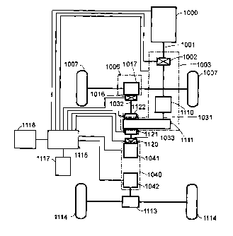
Fig. 1 is a schematic view showing a differential generation power
distribution system of a preferred embodiment of the present invention;
and the preferred embodiment is essentially comprised of:
- a rotational power unit 1000: comprised of an internal combustion
engine, its associate fuel supply and control unit, the ignition unit,
the revolution speed and torque detection and control device, or
comprised of any other rotational power source; its iotational output
shaft 1001 is arranged to drive the controllable clutch 1002 selected
as applicable disposed on the intermediate transmision and control
interface 1003 with speed change function, then to further drive the
main transmission 1110, the main transmission 1110 then drives an
input end 1031 form an intermediate differential gear set 1111,
whereof one differential output end 1032 from the intermediate
-8-
I
CA 02637960 2008-07-15
differential gear set 1111 drives a front end transmission 1006 and
further drives a front end load 1007 while the other differential
output end 1033 of the intermediate differential gear set 1111 drives
the input end of the rotation part from the first electric machine 1041
s of the rotational electric machine assembly 1040; and the output end
of the rotation part of the second electric machine 1042 directly or
through a rear end transmission 1113 drives a rear end load 1114;
- the controllable clutch 1002: an optional item related to one driven
by manual, mechanical, electromagnetic, fluid or eccentric force, or
1 o comprised of one-way transmission device; it is disposed between
the rotational power unit 1000 and the rotational kinetic energy input
end of the main transmission 1110 in the intermediate transmission
and control interface 1003, thus being subjected to the control for
the operation of engagement or disengagement; the controllable
15 clutch 1002 can be optionally installed or not installed as required;
- the intermediate transmission and control interface 1003: includes
(1)
the controllable clutch 1002; (2) the main transmission 1110 related
to an automatic, manual or manually controlled automatic
transmission changing gears and other manual-mechanical operation
20 interface of the prior art for gear shift operation; and (3) the
intermediate differential gear set 1111 which is comprised of
planetary or circulating or any other differential gear set provided
with equivalent function, provided with the input end 1031 and two
differential output ends 1032, 1033; said controllable clutch 1002,
25 the main transmission 1110, and the intermediate differential gear
set 1111 can be optionally installed all or only partly as required;
wherein the input end 1001 of the controllabli clutch 1002 is
provided to be coupled to the rotational kinetic nergy from the
i
rotational power unit 1000 and the output end is provided to be
30 coupled to the main transmission 1110; the output end of the main
-9-
1
CA 02637960 2008-07-15
transmission 1110 is provided to be coupled to the input end 1031 of
the intermediate differential gear set 1111; one differential output
end 1032 of the intermediate differential gear set 1111 is provided to
drive the front end transmission 1006 thus the front end load 1007
through the controllable clutch 1016 and the differential gear set
1017; another differential output end 1033 of the intermediate
differential gear set 1111 is provided to drive the input end of the
rotation part from the first electric machine 1041 of the rotational
electric machine assembly 1040 through the controllable clutch 1120;
o and in turn for the output end of the second electric machine 1042 of
the rotational electric machine assembly 1040 to drive the rear end
load 1114 through the rear end transmission 1113;
- the front end transmission 1006: an optional item provided
depending on the nature of the load, including the optional
differential gear set 1017 with its both differential outputs to drive
the front end load 1007, or an optional single output transmission
gear set in place of the differential gear set 1017 to drive the
individual load or any other load; or when required the controllable
clutch 1016 is disposed between the differential output end 1032 of
the intermediate differential gear set 1111 and the differential gear
set 1017 of the front end transmission 1006 for the control of
engagement or disengagement; furthermore, as required an optional
controllable brake 1122 may be provided to the output end 1032 of
the intermediate differential gear set 1111; said front end
transmission 1006 may be optionally installed or not installed as
required;
- the controllable clutch 1016: it is related to a manual, mechanical,
electromagnetic, fluid or eccentric force driven clutch, or comprised
of one-way transmission device, whereof it is disposed between the
differential output end 1032 of the intermediate differential gear set
-10-
CA 02637960 2008-07-15
1111 and the input end of the differential gear set 1017 of the front
end transmission 1006 to engage or disengage as subject to the
central controller 1118; said controllable clutch 1016 may be
optionally installed or not installed as required;
- a controllable brake 1121: it is related to a manual, mechanical,
electromagnetic or fluid force controlled brake apparatus, whereof it
is disposed to where between the differential output end 1033 of the
intermediate differential gear set 1111 and the static casing to close
or release the brake as subject to the central controller 1118; said
controllable brake 1121 may be optionally installed or not installed
as required;
- a controllable brake 1122: it is related to a manual, mechanical,
electromagnetic or fluid force controlled brake apparatus, whereof it
is disposed between the differential output end 1032 of the
intermediate differential gear set 1111 and the static casing to close
or release the brake as subject to the central controller 1118; said
controllable brake 1122 may be optionally installed or not installed
as required;
- the rotational electric machine assembly 1040: it is provided in the
construction of AC or DC, brush or brushless electric machine,
containing one or a plurality of the first electric machine 1041 and
one or a plurality of the second electric machine 1042 with both
sharing the same holder, the input end of the rotation part of the first
electric machine 1041 is coupled through the controllable clutch
1120 to the differential output end 1033 of the intermediate
differential gear set 1111, the output end of the rotation part of the
second electric machine 1042 drives through the differential rear end
transmission 1113 to drive the rear end load 1114, or an optional
single output transmission gear set is provided n place of the
differential rear end transmission 1113 to drive an iiidividual load or
-11-
CA 02637960 2008-07-15
any other load; wherein the first electric machine 1041 is essentially
operating as a generator and alternatively as a motor; the second
electric machine 1042 is essentially operating as a motor and
alternatively as a generator;
- the controllable clutch 1120: related to a manual, mechanical,
electromagnetic, fluid or eccentric force driven clutch, or comprised
of a one-way transmission, whereof it is provided between the
differential output end 1033 of the intermediate differential gear set
1111 and the input end of the rotation part from the first electric
o machine 1041 of the rotational electric machine assembly 1040 to
engage or disengage as subject to the central controller 1118; said
controllable clutch 1120 may be optionally installed or not installed
as required;
- the central controller 1118: it is comprised of dynamo-electric or
solid state electronic component or microprocessor and associate
operation software to output control command or signal according to
the internal setup or random control by manual for controlling the
drive control device 1115; said central controller 1118 may be
optionally installed or not installed as required;
- the rechargeable device 1117: an optional item related to a
rechargeable secondary battery, capacitor, or super capacitor;
- the front end load 1007: comprised of one or a plurality of wheel
set,
track, or any other load;
- the rear end transmission 1113: provided depending on the nature of
the load containing one or a plurality of differential gear sets for
both differential output ends to drive the rear end load 1114, or a
transmission gear set is disposed to drive an individual rear end load
1114; said rear end transmission 1113 may be optionally installed or
not installed as required;
- the rear end load 1114: comprised of one or a pluralkty of wheel set,
-12-
I
CA 02637960 2008-07-15
track or any other load;
- a drive control device 1115: it is comprised of a dynamo-electric or
solid-state electronic component, connected among the first electric
machine 1041 and the second electric machine 1042 of the rotational
electric machine assembly 1040 and the rechargeable device 1117 to
receive the command from the central controller 1118 to execute
power control and transmission to drive either the first electric
machine 1041 or the second electric machine 1042 or both to engage
in positive or negative revolution functioning as a motor; or for
control either the first electric machine 1041, or the second electric
machine 1042, or both to function as a generator, or for the
executing regulation of input or output amperage and voltage
between the first electric machine 1041 and the second electric
machine 1042 or the rechargeable device 1117 through the drive
control device 1115; or for the control of controllable clutches 1002,
1016, and 1120, or the controllable brakes 1121 and 1122 , or the
intermediate transmission and control interface 1003, or the
rotational power unit 1000 or any other load output control electric
power through the drive control device 1115; said drive control
device 1115 may be optionally installed or not installed as required.
Primary operation functions of the differential generation power
distribution system of the present invention include the coupling of the
rotational kinetic energy output end of the rotational power unit 1000 and
the intermediate transmission and control interface 1003, the intermediate
transmission and control interface 1003 contains the main transmission
1110 comprised of the controllable clutch 1002 and gear shifting device
and the intermediate differential gear set 1111 driven by the main
transmission 1110 while one of the differential outp t ends of the
intermediate different gear set 1111 drives the front e d transmission
1006 to further drive the front end load 1007; the other di' ferential output
-13-
CA 02637960 2008-07-15
end of the intermediate different gear set 111 drives the input end of the
rotation part of the first electric machine 1041 in the rotational electric
machine assembly 1040 while the output end of the rotation part of the
second electric machine 1042 in the rotational electric machine assembly
1040 drives the rear end load 1114 directly or through a transmission; the
rotational electric machine assembly 1040 is subject to the control of the
drive control device 1115 to regulate and control the power distribution
between the front end load 1007 and the rear end load 1114.
In the differential generation power distribution system of the
present invention, the input end 1001 of the controllable clutch 1002 is
coupled to the rotational kinetic energy from the rotational power unit
1000, and its output end is coupled to the main transmission 1110; the
output end of the main transmission 1110 is coupled to the input end
1031 of the intermediate differential gear set 1111; one differential output
end 1032 of the intermediate differential gear set 1111 drives the front
end transmission 1006 through the controllable clutch 1016 and the
differential gear set 1017 thus to drive the front end load 1007; another
differential output end 1033 of the intermediate differential gear set 1111
drives the input end of the rotation part of the first electric machine 1041
in the rotational electric machine assembly 1040 through the controllable
clutch 1120; and further to drive the rear end load 1114 through the rear
end transmission 1113 at the output end of the second clectric machine
1042 in the rotational electric machine assembly 1040.
Both of the first and the second electric machines 1041, 1042 of the
differential generation power distribution system may operate as a motor
or as a generator according to the operation needs. When the first
electric machine 1041 is driven by the rotational kinetic energy from the
differential output end 1033 of the intermediate differential gear set 1111
to function as a generator, the power outputted may provide any or all the
following functions subject to the control of the central controller 1118
-14-
I
CA 02637960 2008-07-15
,
and the drive control device 1115:
(1) With the controllable clutch 1016 disengaged and the
controllable brake 1122 locked up to serve as the engine for
the rotational power unit 1000, the engine as controlled is
running at or approaching a fixed speed within the rpm area of
the brake specific fuel consumption (BSFC) featuring
comparatively higher energy efficiency and more fuel saving
to drive the first electric machine 1041 to operate as a
generator; the power generated drives the second electric
machine 1042 to operate as a motor directly or through the
control by the drive control device 1115, thus to further drive
the rear end load 1114 to start up from static condition and to
execute accelerating operation;
(2) Should the system be provided with the rechargeable device
1117, the controllable clutch 1016 is disengaged and the
controllable brake 1122 is locked up to serve as the engine for
the rotational power unit 1000, the engine as controlled is
running at or approaching a fixed speed within the rpm area of
the brake specific fuel consumption (BSFC) featuring
comparatively higher energy efficiency and more fuel saving
to drive the first electric machine 1041 to operate as a
generator; the power generated charges the unsaturated
rechargeable device 1117 or is supplied to an external
destination;
(3) With the controllable clutch 1016 disengaged and the
controllable brake 1122 locked up to serve as the engine for
the rotational power unit 1000, the engine as controlled is
running at or approaching a fixed speed withir the rpm area of
the brake specific fuel consumption (B FC) featuring
comparatively higher energy efficiency and More fuel saving
-15-
1
CA 02637960 2008-07-15
to drive the first electric machine 1041 to operate as a
generator; the power generated and that from the rechargeable
device 1117 jointly drive the second electric machine 1042 to
function as a motor directly or through the control by the drive
control device 1115 thus to further drive the rear end load
1114 to start up from static status and to execute accelerating
operation;
(4) With the controllable clutch 1016 disengaged and the
controllable brake 1122 locked up to serve as the engine for
the rotational power unit 1000, the engine as controlled is
running at or approaching a fixed speed within the rpm area of
the brake specific fuel consumption (BSFC) featuring
comparatively higher energy efficiency and more fuel saving
to drive the first electric machine 1041 to operate as a
generator; the power generated drives the second electric
machine device 1042 to function as a motor directly or
through the control by the drive control device 1115 to further
drive the rear end load 1114 to start up from the static status
and to execute accelerating operation while charging the
rechargeable device 1117 at the same time;
(5) The power outputted from the first electric machine 1041 as
driven by the rotational kinetic energy from the intermediate
differential gear set 1111 drives the second electric machine
1042 to function as a motor directly or through the drive
control device 1115 thus to further drive the rear end load
1114 to start up from the static status and to execute
accelerating operation;
(6) When the system is provided with the rechargeable device
1117, the rotational kinetic energy from the intermediate
differential gear set 1111 may be applied to drive the first
-16-
CA 02637960 2008-07-15
electric machine 1041 to function as a generator with the
power generated to charge the unsaturated rechargeable device
1117 or supplied to an external destination;
(7) When the system is provided with the rechargeable device
1117, the rotational kinetic energy from the intermediate
differential gear set 1111 may be applied to drive the first
electric machine 1041 to function as a generator with the
power generated to drive the second electric machine 1042 to
function as a motor directly or through the control by the drive
control device 1115 thus to drive the rear end load 1114 to
start up from static status and to execute accelerating
operation while charging the unsaturated rechargeable device
1117 at the same time;
(8) When the system is provided with the rechargeable device
1117, the rotational kinetic energy from the intermediate
differential gear set 1111 may be applied to drive the first
electric machine 1041 to function as a generator with the
power generated and that outputted from the rechargeable
device 1117 to jointly drive the second electric machine 1042
to function as a motor directly or through the control by the
drive control device 1115 thus to further drive the rear end
load 1114 to start up from static status and to execute
accelerating operation;
(9) The second electric machine 1042 is capable of functioning as
a generator in the status of the load brake is applying a brake
or reduction with the power outputted is provided to charge
the rechargeable device 1117 so as to produce damper.
The differential generation power distribution system of the present
invention when applied to an all wheel driving carrier is capable of
providing any or all the following functions through the intermediate
-17-
CA 02637960 2008-07-15
transmission and control interface 1003 and the control by the central
controller 1118:
(1) Power from the rechargeable device 1117 drives the first electric
machine 1041 and the second electric machine 1042 in the rotational
electric machine assembly 1040 for either or both electric machines
to engage in positive or negative revolution as a motor to drive the
load to start up from static status and to execute accelerating
operation; or
(2) Power from the rechargeable device 1117 drives the first electric
o machine 1041 or the second electric machine 1042 in the rotational
electric machine assembly 1040 for either or both of the electric
machines to function as a motor to drive the load jointly with the
rotational kinetic energy from the rotational power unit 1000 (e.g.,
an engine); or to engage in positive or negative revolution as a motor
to regulate and control the power distribution ratio between the front
end load 1007 and the rear end load 1114; or
(3) The rotational kinetic energy from the rotational power unit 1000
drives the first electric machine 1041 of the rotational electric
machine assembly 1040 to function as a generator with the power
outputted to charge the rechargeable device 1117 and to change the
counter torque formed by the power outputted by controlling the size
of the charging current, meanwhile regulating and controlling the
power distribution ratio between the front end load 1007 and the rear
end load 1114 by means of the differential couplin of the counter
torque through the intermediate differentia gear set 1111; or
(4) With the controllable clutch 1016 disengaged and the controllable
brake 1122 locked up to serve as the engine for the otational power
unit 1000, the engine as controlled is running at or approaching a
fixed speed within the rpm area of the brake specific fuel
consumption (BSFC) featuring comparatively higher energy
-18-
CA 02637960 2008-07-15
efficiency and more fuel saving to drive the first electric machine
1041 to operate as a generator; the power generated drives the
second electric machine 1042 to function as a motor directly or
through the control by the drive control device 1115 to further drive
the rear end load 1114 to start up from the static status and to
execute accelerating operation; or
(5) The rotational kinetic energy from the differential output end 1033
of the intermediate differential gear set 1111 drives the first electric
machine 1041 to function as a generator with the power generated to
directly or through the control by the drive control device 1115 drive
the second electric machine 1042 to function as a motor for further
driving the rear end load 1114 to start up from static status and to
execute accelerating operation; or
(6) The rotational kinetic energy from the differential output end 1033
of the intermediate differential gear set 1111 drives the first electric
machine 1041 to function as a generator with the power generated
and that outputted from the rechargeable device 1117 to jointly drive
the second electric machine 1042 to function as a motor directly or
through the control by the drive control device 1115 for further
driving the rear end load 1114 to start up from static status and to
execute accelerating operation; or
(7) When the carrier is driving down a slope or exercising a brake or
deceleration, either or both of the first electric machine 1041 and the
second electric machine 1042 in the rotational electric machine
assembly 1040 functions as a generator to charge the rechargeable
device 1117, or to supply power to other power driven load for
executing the regeneration braking; or
(8) The system engages in front wheel driving; or
(9) The system engages in rear wheel driving; or
(10) The system engages in all wheel driving.
-19-
CA 02637960 2008-07-15
Fig. 2 is a schematic view showing multiple units of rear end loads
are driven by the preferred embodiment of the present invention
illustrated in Fig. 1. The system configuration as illustrated in Fig. 2
while being given with that as illustrated in Fig. 1 is essentially
s characterized in that:
---two or more than two second electric machines 1042 are
respectively disposed to two or more than two rear end load 1114 to be
subject to the control by the drive control device 1115 for separately
driving their corresponding rear end transmissions 1113 thus to drive the
rear end loads 1114 each driven by the rear end transmission 1113.
In the differential generation power distribution system of the
present invention, the rotational electric machine assembly 1040 may be
comprised of multiple separated individual electric machines as
illustrated in Fig. 3 showing a rotational electric machine assembly
comprised of separated individual electric machine of another preferred
embodiment of the present invention. Additional to the system
configuration and functions as illustrated in Fig. 1, the construction as
illustrated in Fig. 3 is further characterized by:
- having an independent first electric machine 1041; and
- having one or a plurality of independent second electric machine
1042 to drive the rear end load 1114 adapted either directly or
through the variable speed transmission device of the prior art.
Fig. 4 is a schematic view showing the preferred embodiment
illustrated in Fig. 3 is provided with multiple units of the second electric
machine and multiple units of rear load. The system configuration of
the preferred embodiment in Fig. 4 while carrying the primary
configuration in Fig. 3, is further characterized by that:
- the independent second electric machine 1042 is each adapted to the
loads on both sides of two or more than two rear end load 1114 for
being subject to the control by the drive control device 1115 without
-20-
CA 02637960 2008-07-15
providing the rear end transmission 1113 for increasing space and
improving efficiency; or
- a directly driven wheel type electric machine may be provided
between the second electric machine 1042 and the rear end load
1114; or the rear end load 1114 is driven by the second electric
machine 1042 directly or through a variable speed transmission of
the prior art with the functions and working principles of the system
similar to that for the preferred embodiment given in Fig. 3.
In the differential generation power distribution system of the
present invention, the rotational electric machine assembly 1040 while
being comprised of the rotational electric machine structures sharing the
same construction as illustrated in Figs. 1 and 2, may form another
rotational electric machine assembly 10410 by having those rotation parts
to indicate coaxially arranged in series. As illustrated in Fig. 5, a
construction of another preferred embodiment yet showing that the
present invention having its rotation parts coaxially disposed in series to
form a rotational electric machine assembly, while carrying the system
configuration and functions of the preferred embodiment illustrated in Fig.
1, it is characterized by that:
- a rotation part 10411 of the first electric machine and a rotation part
10412 of the second electric machine are coaxially arranged in series;
the rotation part 10412 of the second electric machine drives at least
one rear end load 1114 directly or through at least one rear end
transmission 1113; and
- an electric machine static part 10413 serving as a common magnetic
path is provided extending axially to be coupled to the rotation part
10411 of the first electric machine and the rotation part 10412 of the
second electric machine.
Fig. 6 is a schematic view showing that the preferred embodiment
illustrated in Fig. 5 is provided with multiple units of the rear end load.
-21-
I
CA 02637960 2008-07-15
,
v .
The system configuration of the preferred embodiment in Fig. 6 while
carrying the primary configuration in Fig. 5, is further characterized by
that:
- rotation parts are coaxially arranged in series to form the
rotational
s electric machine assembly 10410 and an electric machine static part
10413 sharing a common magnetic path is provided extending
axially along where both rotation parts 10411, 10412 respectively of
the first and the second electric machine arranged coaxially in series,
and coupled to the rotation part 10411 of the individually provided
first electric machine and the rotation part 10412 of the second
electric machine also individually provided coaxially in series with
the first electric machine;
The electric machine static part 10413 sharing a common
magnetic path is arranged coaxially in series with its internally
coupled rotation parts 10411, 10412 respectively of the first and the
second electric machines; and the rotation part 10412 of the second
electric machine drives one or multiple rear end load 1114 either
directly or through one or multiple rear end transmission 1113;
As required, the electric machine static part 10413 sharing a
common magnetic path may become a magnetic field or armature for
the electric machine while both rotation parts 10411, 10412
respectively of the first and the second electric machines may also
function as the magnetic field or armature for the electric machine as
relatively selected if and when required; the system functions and
working principles are the same as that given in Fig. 5.
Fig. 21 is a schematic view of the present invention bowing that the
rotation part of the electric machine indicates coaxial construction in
series of a rotational electric machine assembly.
In the differential generation power distribution system of the
present invention, the rotational electric machine assembly 10410 may be
-22-
I
CA 02637960 2008-07-15
,
,
comprised of having rotations parts arranged in parallel of multiple axes
coupled to the electric machine static part sharing a common magnetic
path while the rotational electric machine assembly is in the construction
of a rotational electric construction sharing the same structure as
illustrated in Figs. 1 and 2.
Fig. 7 is a schematic view of another preferred embodiment of the
present invention showing that multiple axes from the rotation part of the
electric machine coupled in parallel with the static part of the electric
machine that shares the same magnetic path. The construction of the
1 o preferred
embodiment as illustrated in Fig. 7 while maintaining the
system configuration and function as that given in Fig. 1 is further
characterized by that:
- the rotation part 10411 of the first electric machine and the
rotation
part 10412 of the second electric machine are arranged in parallel on
multiple axes; and the rotation part 10412 of the second electric
machine drives the rear end load 1114 either directly or through the
rear end transmission 1113; and
- a closed magnetic path is formed by having both rotation parts
10411, 10412 respectively of the first and the second electric
machines to couple to the electric machine static part 10413 sharing
the same magnetic path.
Fig. 8 is a schematic view showing that the preferred embodiment
illustrated in Fig. 7 is provided with multiple units of rear end load. The
construction of the preferred embodiment as illustrated in Fig. 8 while
maintaining the system configuration and function as that given in Fig. 7
is further characterized by that:
- the rotational electric machine assembly 10410 i comprised of
having both rotation parts 10411, 10412 respectively of the first and
second electric machines individually provided to be arranged in
parallel of multiple axes and coupled to the electric machine static
-23-
I
CA 02637960 2008-07-15
,
,
part 10413 sharing a common magnetic path; and the rotation part
10411 of the first electric machine and the rotation part 10412 of the
second electric machine coupled to the electric machine static 10413
sharing a common magnetic path are arranged in parallel of multiple
axes while the rotation part 10412 of the second electric machine
drives one or multiple rear end loads 1114 either directly or through
the rear end transmission 1113.
As required, the electric machine static part 10413 sharing a
common magnetic path may become a magnetic field or an armature
'0 for the
electric machine while both rotation parts 10411, 10412
respectively of the first and the second electric machines may also
function as the magnetic field or armature for the electric machine if
and when required; the system functions and working principles are
the same as that given in Fig. 7.
Fig. 22 is a schematic view of the present invention showing a
construction of the rotational electric machine assembly having its
rotation part comprised of multiple axes coupled in parallel with the static
part of the electric machine sharing a common magnetic path.
Other than having the rotational electric machine assembly 1040 in
the differential generation power distribution system of the present
invention comprised of rotational electric machine structure sharing the
same construction as illustrate din Figs. 1 and 2, the rotational electric
machine assembly 10410 may be comprised of electric machines
coaxially arranged in a construction of three layers in a circular fashion.
Fig. 9 is a schematic view of another preferred embodiment of the present
invention showing a rotational electric machine assembly comprised of
ci.
the three-layer ring-shaped type coaxial electric machii e construction.
The construction of the preferred embodiment illustrate in Fig. 9 while
maintaining the system configuration and functions given in Fig. 1 is
further characterized by that:
-24-
CA 02637960 2008-07-15
- the rotation part 10411 of the first electric machine in a circular
or
cylindrical shape and the rotation part 10412 of the second electric
machine in a circular shape presents with the electric machine static
part 10413 sharing a common magnetic path and disposed between
both rotation parts 10411, 10412 a three-layer type ring-shaped
coaxial electric machine construction; and the rotation part 10412 of
the second electric machine drives the rear end load 1114 either
directly or through the rear end transmission 1113.
Fig. 10 is a schematic view showing that the preferred embodiment
o illustrated in Fig. 9 is provided with multiple units of rear end load.
The
construction of the preferred embodiment as illustrated in Fig. 10 while
maintaining the system configuration and function as that given in Fig. 9
is further characterized by that:
- the rotational electric machine assembly 10410 in a construction of
three-layer type ring-shaped coaxial electric machines indicates an
electric machine structure featuring three layers of coaxially
arranged electric machines coupling to one another; wherein, the
ring-shaped central layer is provided as an electric machine static
part 10413 sharing a common magnetic path; the ring-shaped outer
layer and the ring- or cylinder-shaped inner layer are respectively
functioning as the individually operating rotation part 10411 of the
first electric machine and the rotation part 10412 of the second
electric machine; and the rotation part 10412 of the second electric
machine drives one or multiple rear end loads 1114 either directly or
through the rear end transmission 1113;
As required, the electric machine static part 10413 sharing a
common magnetic path may become a magnetic field or an armature
for the electric machine while both rotation parts 10411, 10412
respectively of the first and the second electric machines may also
respectively function as the magnetic fields or armatures for the
-25-
CA 02637960 2008-07-15
electric machine that engages in relative operation if and when
required; the system functions and working principles are the same
as that given in Fig. 9.
Fig. 23 is a schematic view of the present invention showing a
rotational electric machine assembly comprised of a three-layer
ring-shaped coaxial electric machine structure.
In order to have the rotational kinetic energy from the rotational
power unit 1000 of the differential generation power distribution system
of the present invention to directly drive the rear end load 1114, any of
o those preferred embodiments given in Figs. 1 through 4 may be first
provided a controllable clutch 1116 subject to the control by the central
controller 1118 and the drive control device 1115 at where between both
rotation parts of the first and the second electric machines 1041, 1042 of
the rotational electric machine assembly 1040. When the controllable
clutch 1116 indicates engaged status, the rotational kinetic energy from
the rotational power unit 1000 is inputted through the rotation part of the
first electric machine 1041 to the rotation part of the second electric
machine 1042 through the controllable clutch 1116 in engaged status, and
further for the output end of the rotation part of the second electric
machine 1042 to drive the rear end load 1114.
Fig. 11 is a schematic view of another preferred embodiment of the
present invention showing that a controllable clutch is provided between
the rotation part of the first electric machine and that of the second
electric machine illustrated in Fig. 1.
Fig. 12 is a schematic view of another preferred embodiment of the
present invention showing that a controllable clutch is provided between
the rotation part of the first electric machine and that of the second
electric machine illustrated in Fig. 2
Fig. 13 is a schematic view of another preferred enthodiment yet of
the present invention showing that a controllable clutch is provided
-26-
CA 02637960 2008-07-15
between the rotation part of the first electric machine and that of the
second electric machine illustrated in Fig. 3.
Fig. 14 is a schematic view of another preferred embodiment yet of
the present invention showing that a controllable clutch is provided
s between the
rotation part of the first electric machine and that of the
second electric machine illustrated in Fig. 4.
The controllable clutch 1116 illustrated in Figs. 11 through 14
includes that driven by manual, mechanical, electromagnetic, fluid, or
eccentric force, or a one-way transmission; the controllable clutch 1116 is
o provided
between both rotation parts of the first electric machine 1041
and the second electric machine 1042 in the rotational electric machine
assembly 1040, and is subject to the control by the central controller 1118
to engage or disengage the rotation part of the first electric machine 1041
with or from the rotation part of the second electric machine 1042. The
15 controllable
clutch may be optionally installed or not installed as
required.
With the controllable clutch 1116 elected to be disposed between
both rotation parts of the first and the second electric machines 1041,
1042, the system provides any or all of the following functions:
20 (1) With the
controllable clutch 1116 in engaged status, the rotational
kinetic energy outputted from the differential output end 1033 of the
intermediate differential gear set 1111 drives the rotation part of the
first electric machine 1041 through another controllable clutch 1120,
and then drives the rotation part of the second electric machine 1042
25 through the
controllable clutch 1116 so to drive the rear end load
1114 through the rear end transmission 1113;
(2) With the controllable clutch 1116 in engaged status, the power
outputted from the rechargeable device 1117 drives each of both the
first and the second electric machines 1041, 1042 to function as a
30 motor through the control by the drive control devicC 1115; and
-27-
CA 02637960 2008-07-15
(3) With the controllable clutch 1116 in engaged status, both of the
first
and the second electric machines 1041, 1042 are jointly drawn by
the rotational power source 1000 or a load inertia to function as a
generator with the power generated to charge the rechargeable
device 1117 or supply power to any other power driven load through
the drive control device 1115.
In practice, any of the differential generation power distribution
system illustrated in Figs. 1 through 4 and Figs. 11 through 14 may
further include any or all of the following devices and functions to meet
io the individual application requirements:
- the differential output end 1032 of the intermediate differential
gear
set 1111 may first be adapted with a controllable brake 1122 or a
controllable clutch 1016 before being coupled with the front end
transmission 1006 so to drive the front end load 1007 through the
15 differential gear set 1017 of the front end transmission 1006; the
controllable brake 1122 and the controllable clutch 1016 may be
separately provided or sharing the common structure, and either or
both of the controllable brake 1122 and the controllable clutch 1016
may be optionally installed or not installed as required;
20 - with the controllable clutch 1016 disposed between the differential
output end 1032 of the intermediate differential gear set 1111 and
the front end transmission 1006 in disengaged status, the
controllable brake 1122 in the braking status, another controllable
clutch 1120 disposed between the other differential output end 1033
25 of the intermediate differential gear set 1111 and the rotational
electric machine assembly 1040 in engaged status, and another
controllable brake 1121 in released status, the front end load 1007
indicates idling and the system drives the rear end load 1114;
- the other differential output end 1033 of the intermediate
differential
30 gear set 111 may be first adapted with the controllable brake 1121,
-28-
CA 02637960 2008-07-15
or the controllable clutch 1120 before coupling to the input end of
the first electric machine 1041 of the rotational electric machine
assembly 1040; both of the controllable brake 1121 and the
controllable clutch 1120 may be separately provided or sharing the
same structure, and either or both of the controllable brake 1121 and
the controllable clutch 1120 may be optionally installed or not
installed as required;
- with the controllable clutch 1120 disposed between the differential
output end 1033 of the intermediate differential gear set 1111 and
o the
rotational electric machine assembly 1040 in disengaged status,
the controllable brake 1122 in the braking status, another
controllable clutch 1016 disposed between the differential output
end 1032 of the intermediate differential gear set 1111 and the front
end transmission 1006 in engaged status, and the controllable brake
1122 in released status; the front end load indicates idling and the
system drives the rear end load 1114; the rotational kinetic energy
from the rotational power unit 1000 drives the front end load 1007
through the main transmission 1110, the differential output end 1032
of the intermediate differential gear set 1111, and the front end
transmission 1006 while the rear end load 1114 is left in a skidding
status; or
(1) when the rechargeable device 1117 is provided, the power
from the rechargeable device 1117 drives the second electric
machine 1042 through the drive control device 1115 to
function as a motor so that the power outputted from the
rechargeable device 1117 drives the second electric machine
1042 to function as a motor to drive the rear end load 1114 at
the same time while the rotational kinetic energy from the
rotational power unit 1000 drives the second electric machine
1042 to function as a motor;
-29-
CA 02637960 2008-07-15
(2) if the
front end load 1007 and the rear end load 1114 are of an
integrated load type, such as the load on ground, on surface or
in water, the second electric machine 1042 is drawn by the
rear end load 1114 to function as a generator when the
rotational kinetic energy from the rotational power unit 1000
is driving the front end load 1007; and the power generated
charges the rechargeable device 1117 or supplies power to any
other power driven load;
- with
the controllable clutch 1016 disposed between the differential
output end 1032 of the intermediate differential gear set 1111 and
the front end transmission 1006 in engaged status, the controllable
brake 1122 in released status, another controllable brake 1121
adapted to the other differential output end 1033 in released status;
and another controllable clutch 1120 adapted in engaged status; the
present invention provides the following functions:
(1) the rotational kinetic energy from the rotational power unit
1000 executes all wheel driving; or
(2) when the rechargeable device 1117 is provided, the power
from the rechargeable device 1117 drives the first electric
machine 1041 or the second electric machine 1042 through the
drive control device 1115 for either electric machine to
execute all wheel driving alone or jointly with the rotational
kinetic energy from the rotational power unit 1000;
- with
the controllable clutch 1016 disposed between the differential
output end 1032 of the intermediate differential gear set 1111 and
the front end transmission 1006 in disengaged status, the
controllable brake 1122 in released status, the controllable brake
adapted to the other differential output end 1033 in released status,
the controllable clutch 1120 adapted to the input end of the
rotational electric machine assembly 1040 in disengaged status; both
-30-
CA 02637960 2008-07-15
of the front end and the rear end loads are left in skidding status; and
in the course of deceleration or driving down slope or upon
exercising a brake, either or both of the first electric machine 1041
and the second electric machine 1042 of the rotational electric
machine assembly 1040 revolves to function as a generator when
drawn by the load inertia with the power outputted to charge the
rechargeable device 1117 or to supply power to any other power
driven load through the drive control device 1115 while the counter
torque created by the outputted power serves as the braking damp
o for the system;
- the controllable clutch 1116 may be disposed as required at where
between the first electric machine 1041 and the second electric
machine 1042 of the rotational electric machine assembly 1040 so
that when the controllable clutch 1116 is in engaged status, both
15 rotation parts respectively of the first electric machine 1041 and the
second electric machine 1042 are also in engaged status; or in the
absence of the controllable clutch 1116, rotation parts respectively
of the first electric machine 1041 and the second electric machine
1042 are separated from each other without being coupled for
20 transmission; and
- with the controllable clutch 1116 disposed between the first and the
second electric machine 1041, 1042 and placed in engaged status,
the rotational kinetic energy from the rotational power unit 1000
drives the rear end load 1114 through another controllable clutch
25 1002, the main transmission 1110, the intermediate differential gear
set 1111, and the rotational electric machine assembly 1040 with the
controllable clutch 1116 in engaged status inside.
Any preferred embodiment of the differential generation power
distribution system as illustrated in Figs. 5 through 10 is capable of
30 directly driving the rear end load 1114 from the rotational power unit
-31-
CA 02637960 2008-07-15
1000; and a controllable clutch 1116 subject to the control by the central
controller 1118 and the drive control device 1115 may be further
disposed in series at where between the rotation part 10411 of the first
electric machine and the rotation part 10412 of the second electric
machine of the rotational electric machine assembly 10410;
With the controllable clutch 1116 in its engaged status, the rotational
kinetic energy from the rotational power unit 1000 is inputted through the
rotation part 10411 of the first electric machine to pass through the
controllable clutch 1116 in engaged status to the rotation part 10412 of
o the second electric machine for the output end of the rotation part 10412
of the second electric machine to drive the rear end load 1114.
Fig. 15 is a schematic view of another preferred embodiment of the
present invention showing that a controllable clutch is provided between
the rotation part of the first electric machine and that of the second
electric machine illustrated in Fig. 5.
Fig. 16 is a schematic view of another preferred embodiment of the
present invention showing that a controllable clutch is provided between
the rotation part of the first electric machine and that of the second
electric machine illustrated in Fig. 6.
Fig. 17 is a schematic view of another preferred embodiment of the
present invention showing that a controllable clutch is provided between
the rotation part of the first electric machine and that of the second
electric machine illustrated in Fig. 7.
Fig. 18 is a schematic view of another preferred embodiment of the
present invention showing that a controllable clutch is provided between
the rotation part of the first electric machine and that of the second
electric machine illustrated in Fig. 8.
Fig. 19 is a schematic view of another preferred embodiment of the
present invention showing that a controllable clutch is provided between
the rotation part of the first electric machine and that of the second
-32-
CA 02637960 2008-07-15
electric machine illustrated in Fig. 9.
Fig. 20 is a schematic view of another preferred embodiment of the
present invention showing that a controllable clutch is provided between
the rotation part of the first electric machine and that of the second
electric machine illustrated in Fig. 10.
The controllable clutch 1116 illustrated in Figs 15 through 20 added
to each preferred embodiment of the present invention includes that
driven by manual, mechanical, electromagnetic, fluid or eccentric force,
or one that is comprised of a one-way transmission; the controllable
o clutch 1116 is disposed between the rotation part 10411 of the first
electric machine and the rotation part 10412 of the second electric
machine of the rotational electric machine assembly 10410 and is subject
to the control by the central controller 1118 to engage or disengage the
rotation part 10411 of the first electric machine with or from the rotation
part 10412 of the second electric machine; said controllable clutch 1116
may be optionally installed or not installed as required.
When the controllable clutch 1116 is elected to be disposed between
the rotation part 10411 of the first electric machine and the rotation part
10412 of the second electric machine, the system provides any or all of
the following functions:
(1) With the controllable clutch 1116 in engaged status, the rotational
kinetic energy outputted from the differential output end 1033 of the
intermediate differential gear set 1111 drives the rotation part 10411
of the first electric machine through another controllable clutch 1120,
and then drives the rotation part 10412 of the second electric
machine through the controllable clutch 1116 so to drive the rear end
load 1114 through the rear end transmission 1113;
(2) With the controllable clutch 1116 in engaged status, the power
outputted from the rechargeable device 1117 drives both rotation
parts 10411, 10412 respectively of the first and the second electric
-33-
CA 02637960 2008-07-15
machines to function as a motor through the control by the drive
control device 1115; and
(3) With the controllable clutch 1116 in engaged status, both rotation
parts 10411, 10412 respectively of the first and the second electric
machines are jointly drawn by the rotational power source 1000 or a
load inertia to function as a generator with the power generated to
charge the rechargeable device 1117 or supply power to any other
power driven load through the drive control device 1115.
In practice, any of the differential generation power distribution
o system illustrated in Figs. 5 through 10 and Figs. 15 through 20 may
further include any or all of the following devices and functions to meet
the individual application:
- the controllable brake 1122 may be adapted to the differential
output
end 1032 of the intermediate differential gear set 1111, or the
controllable clutch 1016 is provided before connecting the front end
transmission 1006 to drive the front end load 1007 through the
differential gear set 1017 of the front end transmission 1006; the
controllable brake 1122 and the controllable clutch 1016 may be
separately provided or sharing the same structure; either or both of
said controllable brake 1122 and said controllable clutch 1016 may
be optionally installed or not installed as required;
- with the controllable clutch 1016 disposed between the differential
output end 1032 of the intermediate differential gear set 1111 and
the front end transmission 1006 in disengaged status, the
controllable brake 1122 in braking status, the controllable clutch
1120 disposed between another differential output end 1033 of the
intermediate differential gear set 1111 and the rotational electric
machine assembly 10140 in engaged status, and the controllable
brake 1121 in released status; the front end load 1007 indicates
idling and the system drives the rear end load 1114;
-34-
CA 02637960 2008-07-15
=
- the
controllable 1121 as required may be adapted to another
differential output end 1033 of the intermediate differential gear set
1111, or the controllable clutch 1120 may be provided before
coupling to the input end of the rotation part 10411 of the first
electric machine of the rotational electric machine assembly 10410;
the controllable brake 1121 and the controllable clutch 1120 may be
separately provided or sharing the same structure; either or both of
said controllable brake 1121 and said controllable clutch 1120 may
be optionally installed or not installed as required;
- the
controllable clutch 1120 disposed between the differential output
end 1033 of the intermediate differential gear set 1111 and the
rotational electric assembly 10410 is in disengaged status, the
controllable brake 1121 is in braking status, and the controllable
clutch 1016 disposed between the differential output end 1032 of the
intermediate differential gear set 1111 and the front end transmission
1006 in engaged status, the controllable brake 1122 in released
status; in the meantime, the rotational kinetic energy from the
rotational power unit 1000 drives the front end load 1007 through
the main transmission 1110, the differential output end 1032 of the
intermediate differential device 1111, and the front end transmission
1006 leaving the rear end load 1114 to indicate skidding status; or
(1) when the rechargeable device 1117 is provided, the power from
the rechargeable device 1117 drives the rotation part 10412 of
the second electric machine through the drive control device
1115 to function as a motor so that the power outputted from
the rechargeable device 1117 directly or through the drive
control device 1115 drives the rotation part 10412 of the
second electric machine to function as a motor and to drive the
rear end load 1114 at the same time while the rotational kinetic
energy from the rotational power unit 1000 drives the front end
-35-
I
CA 02637960 2008-07-15
,
,
,
load 1007;
(2) if the front end load 1007 and the rear end load 1114 are of an
integrated load type, such as the load on ground, on surface or
in water, the rotation part 10412 of the second electric machine
is drawn by the rear end load 1114 to function as a generator
when the rotational kinetic energy from the rotational power
unit 1000 is driving the front end load 1007; and the power
generated charges the rechargeable device 1117 or supplies
power to any other power driven load;
'0 - with
the controllable clutch 1016 disposed between the differential
output end 1032 of the intermediate differential gear set 1111 and
the front end transmission 1006 in engaged status, the controllable
brake 1122 in released status, another controllable brake 1121
adapted to the other differential output end 1033 in released status;
and the controllable clutch 1120 adapted in engaged status; the
present invention provides the following functions:
(1) the rotational kinetic energy from the rotational power unit
1000 executes all wheels driving; or
(2) when the rechargeable device 1117 is provided, the power from
the rechargeable device 1117 drives the rotation part 10411 of
the first electric machine or the rotation part 10412 of the
second electric machine through the drive control device 1115
for either electric machine to execute all wheels driving alone
or jointly with the rotational kinetic energy from the rotational
power unit 1000;
- with the controllable clutch 1016 disposed between the differential
output end 1032 of the intermediate differential gar set 1111 and
the front end transmission 1006 in disengaged status, the
controllable brake 1122 in released status, the controllable brake
adapted to the other differential output end 1033 in released status,
-36-
1
1
CA 02637960 2008-07-15
the controllable clutch 1120 adapted to the input end of the
rotational electric machine assembly 10410 in disengaged status;
both of the front end and the rear end loads are left in skidding status;
and in the course of deceleration or driving down slope or upon
exercising a brake, either or both of the rotation parts 10411, 10412
respectively of the first electric machine and the second electric
machine of the rotational electric machine assembly rotates to
function as a generator when drawn by the load inertia with the
power outputted to charge the rechargeable device 1117 or to supply
power to any other power driven load through the drive control
device 1115 while the counter torque created by the outputted power
serves as the braking damp for the system;
- the controllable clutch 1116 may be disposed as required at where
between the rotation part 10411 of the first electric machine and the
rotation part 10412 of the second electric machine of the rotational
electric machine assembly 10410 so that when the controllable
clutch 1116 is in engaged status, both rotation parts 10411, 10412
respectively of the first electric machine and the second electric
machine are in coupled status; or in the absence of the controllable
clutch 1116, the rotation part 10411 of the first electric machine and
the rotation part 10412 of the second electric machine are separated
from each other without being coupled for transmission; and
- with the controllable clutch 1116 disposed between the rotation part
10411 of the first electric machine and the rotation part 10412 of the
second electric machine in engaged status, the rotational kinetic
energy from the rotational power unit 1000 drives the rear end load
1114 through another controllable clutch 1002, the main
transmission 1110, the intermediate differential gear set 1111, and
the rotational electric machine assembly 10410 internally coupled to
the controllable clutch 1116.
-37-
CA 02637960 2008-07-15
When the controllable clutch 1116 disposed between both rotation
parts respectively of the first and the second electric machines 1041, 1042
in the rotational electric machine assembly 1040 as illustrated in Figs. 11
through 14 is in engaged status to drive the rear end load 1114; or the
controllable clutch 1116 disposed between both rotation parts 10411,
10412 respectively of the first and the second electric machines in the
rotational electric machine assembly 10410 as illustrated in Figs. 15
through 20 is in coupled status to drive the rear end load 1114; the inertial
load becomes greater. For the optimized performance of the present
invention to reduce the possibilities of the system operation response and
the service life of the rotational electric machine assembly 1040 or 10410,
and those transmission mechanical members including the controllable
clutches to be affected by the increased inertial amount, a modified
design by providing the transmission and the controllable clutch arranged
in parallel to both input and output ends of the rotational kinetic energy
of the rotational electric machine assembly as illustrated in Figs. 24, 25,
26, and 27 may be provided.
Fig. 24 is a schematic view showing both input and output ends of
the rotational kinetic energy of the rotational electric machine assembly
of Fig. 1 are disposed in parallel with a transmission and a controllable
clutch.
Fig. 25 is a schematic view showing both input and output ends of
the rotational kinetic energy of the rotational electric machine assembly
of Fig. 5 are disposed in parallel with a transmission and a controllable
clutch.
Fig. 26 is a schematic view showing both input and output ends of
the rotational kinetic energy of the rotational electric machine assembly
of Fig. 7 are disposed in parallel with a transmission and a controllable
clutch.
Fig. 27 is a schematic view showing both input and output ends of
-38-
I
CA 02637960 2008-07-15
the rotational kinetic energy of the rotational electric machine assembly
of Fig. 9 are disposed in parallel with a transmission and a controllable
clutch.
In the structure of the preferred embodiment as illustrated in Fig. 24,
the transmission and the controllable clutch may be disposed in parallel to
replace that illustrated in Figs. 11 through 14, wherein, a controllable
clutch is provided in series between both rotation parts respectively of the
first and the second electric machines 1041, 1042. The
related
modification of structure is essentially comprised of:
- a transmission 1080 is disposed between the differential output end
1033 of the intermediate differential gear set 1111 and the
controllable clutch 1120, and an output end 1034 of the transmission
1080 is coupled to one operating end of the controllable clutch 1116;
- a
controllable clutch 1123 is disposed between the output end of the
rotation part of the second electric machine 1042 of the rotational
electric machine assembly 1040 and the rear end transmission 1113,
another transmission 1090 is further provided between the
controllable clutch 1123 and the rear end transmission 1113; and an
output end 1035 of the transmission 1090 is coupled to another
operating end of the controllable clutch 1116;
- the transmission 1080 and the transmission 1090 are each comprised
of gear, friction gear, pulley, gear pulley, chain, or fluidity
transmission, or electromagnetic transmission or other transmission
of the prior art for the structure to provide any or all of the following
functions:
(1) With both controllable clutches 1116, 1016 dis ngaged and the
controllable brake 1122 locked up to serve as t e engine for the
rotational power unit 1000, the engine as cont tolled is running
at or approaching a fixed speed within the rpm area of the brake
specific fuel consumption (BSFC) featuring comparatively
-39-
CA 02637960 2008-07-15
higher energy efficiency and more fuel saving to drive the first
electric machine 1041 to operate as a generator; the power
generated drives the second electric machine 1042 to operate as
a motor directly or through the control by the drive control
device 1115, thus to further drive the load to start up from static
condition and to execute accelerating operation;
(2) Should the system be provided with the rechargeable device
1117, both controllable clutches 1116, 1016 are disengaged and
the controllable brake 1122 is locked up to serve as the engine
for the rotational power unit 1000, the engine as controlled is
running at or approaching a fixed speed within the rpm area of
the brake specific fuel consumption (BSFC) featuring
comparatively higher energy efficiency and more fuel saving to
drive the first electric machine 1041 to operate as a generator;
the power generated charges the unsaturated rechargeable
device 1117 or is supplied to an external destination;
(3) With the system provided with the rechargeable device 1117,
the system while providing the function as described in
paragraph (1) charges the rechargeable device 1117 at the same
time;
(4) With the system provided with the rechargeable device 1117,
the system while providing the function as described in
paragraph (1) drives the second electric machine 1042 jointly
with the power from the rechargeable device 1117 directly or
through the drive control device 1115 to further drive the load;
(5) When both of the controllable clutches 11210, 1123 are in
disengaged status, and the controllable cluich 1116 is in
engaged status, the rotational kinetic energy from the rotational
power unit 1000 drives the rear end load 1114 through the
controllable clutch 1116; meanwhile, both rotation parts
-40-
CA 02637960 2008-07-15
respectively of the first and the second electric machines 1041,
1042 are in free status without being driven;
(6) When the controllable clutch 1123 is in disengaged status, and
both of the controllable clutches 1120, 1116 are in engaged
status, the rotational kinetic energy from the rotational power
unit 1000 drives the rear end load 1114 through the controllable
clutch 1116; meanwhile, the first electric machine 1041 is
driven to function as a generator to charge the rechargeable
device 1117 or supply power to other power driven load, and
the second electric machine 1042 is left in free status without
being driven;
(7) When the controllable clutch 1120 is in disengaged status, and
both of the controllable clutches 1123, 1116 are in engaged
status, the rotational kinetic energy from the rotational power
unit 1000 drives the rear end load 1114 through the controllable
clutch 1116; meanwhile, the second electric machine 1042 is
driven to function as a generator to charge the rechargeable
device 1117 or supply power to other power driven load;
(8) When the controllable clutch 1120 is in disengaged status, the
controllable clutch 1123 is in engaged status, and the
controllable clutch 1116 may be in engaged or disengaged
status, thus while the carrier is driving down slope or exercising
a brake the controllable clutch 1116 can be manipulated to be in
engaged or disengaged status for the load side to reversely drive
either or both of the first and the second electric machines 1041,
1042 for regenerating power to charge the rechargeable device
1117 or supply power to other power driven load;
(9) When all the controllable clutches 1120, 1123, 1116 are in
engaged status, the rotational kinetic energy from the rotational
power unit 1000 drives the rear end load 1114 through the
-41-
I
CA 02637960 2008-07-15
,
controllable clutch 1116, either or both of the first and the
second electric machines 1041, 1042 functions as a generator to
charge the rechargeable device 1117 or supply power to other
power driven load; and when the carrier is exercising
deceleration or driving down slope, either or both of the first
and the second electric machines 1041, 1042 functions as a
generator subject to the control by those controllable clutches
1123, 1116, 1120 to charge the rechargeable device 1117 or
supply power to other power driven load;
(10) When the controllable clutches 1120, 1116 are in disengaged
status, and the controllable clutch 1123 is in engaged status,
power form the rechargeable device 1117 drives the first
electric machine 1041 directly or through the control by the
drive control device 1115 to function as a motor to drive the
rear end load 1114;
(11) When all the controllable clutches 1120, 1116, 1123 are in
engaged status, power form the rechargeable device 1117 drives
both of the first and the second electric machines 1041, 1042
directly or through the control by the drive control device 1115
for either or both of the first and the second electric machines
1041, 1042 to function as a motor; and
:
(12) Among those functions as described abov, , both of the
controllable clutch 1120 that controls the first lectric machine
1041 and the controllable clutch 1123 that controls the second
electric machine 1042 may be in the disengaged status to
facilitate exercising an emergency brake by reducing the inertial
amount of the system.
In the structure of the preferred embodiment illustrated in Figs. 25,
26, and 27, the transmission and the controllable clutch may be arranged
in parallel to replace that illustrated in Figs. 15 through 20, wherein, a
-42-
CA 02637960 2008-07-15
controllable clutch is disposed to be series connected between both
rotation parts 10411, 10412 respectively of the first and the second
electric machines. The
modification by the arrangement of the
transmission and the controllable clutch in parallel is essentially
comprised of:
- the transmission 1080 is disposed between the differential output
end 1033 of the intermediate differential gear set 1111 and the
controllable clutch 1120, and the output end 1034 of the
transmission 1080 is coupled to one operating end of the
controllable clutch 1116;
- the controllable clutch 1123 is disposed between the output end of
the rotation part 10412 of the second electric machine of the
rotational electric machine assembly 10410 and the rear end
transmission 1113, another transmission 1090 is further provided
between the controllable clutch 1123 and the rear end transmission
1113; and an output end 1035 of the transmission 1090 is coupled to
another operating end of the controllable clutch 1116;
- both of the transmission 1080 and the transmission 1090 are each
comprised of gear, friction gear, pulley, gear pulley, chain, or
fluidity transmission, or electromagnetic transmission or other
transmission of the prior art for the structure to provide any or all of
the following functions:
(1) With both controllable clutches 1116, 1016 disengaged and
the controllable brake 1122 locked up to serve as the engine
for the rotational power unit 1000, the engine as controlled is
running at or approaching a fixed speed withir_ the rpm area of
the brake specific fuel consumption (BSFC) featuring
comparatively higher energy efficiency and more fuel saving
to drive the rotation part 10411 of the first electric machine to
operate as a generator; the power generated drives the rotation
-43-
CA 02637960 2008-07-15
part 10412 of the second electric machine to operate as a
motor directly or through the control by the drive control
device 1115, thus to further drive the load to start up from
static condition and to execute accelerating operation;
(2) Should the system be provided with the rechargeable device
1117, both controllable clutches 1116, 1016 are disengaged
and the controllable brake 1122 is locked up to serve as the
engine for the rotational power unit 1000, the engine as
controlled is running at or approaching a fixed speed within
the rpm area of the brake specific fuel consumption (BSFC)
featuring comparatively higher energy efficiency and more
fuel saving to drive the rotation part 10411 of the first electric
machine to operate as a generator; the power generated
charges the unsaturated rechargeable device 1117 or is
supplied to an external destination;
(3) With the system provided with the rechargeable device 1117,
the system while providing the function as described in
paragraph (1) charges the rechargeable device 1117 at the
same time;
(4) With the system provided with the rechargeable device 1117,
the system while providing the function as described in
paragraph (1) drives the rotation part 10412 of the second
electric machine jointly with the power from the rechargeable
device 1117 to further drive the load;
(5) When both of the controllable clutches 1120, 1123 are in
disengaged status, and the controllable clt4ch 1116 is in
engaged status, the rotational kinetic enlergy from the
rotational power unit 1000 drives the rear end load 1114
through the controllable clutch 1116; meanwhile, both rotation
parts 10411, 10412 respectively of the first and the second
-44-
CA 02637960 2008-07-15
electric machines are in free status without being driven;
(6) When the controllable clutch 1123 is in disengaged status, and
both of the controllable clutches 1120, 1116 are in engaged
status, the rotational kinetic energy from the rotational power
unit 1000 drives the rear end load 1114 through the
controllable clutch 1116; meanwhile, the rotation part 10411
of the first electric machine is driven to function as a generator
to charge the rechargeable device 1117 or supply power to
other power driven load, and the rotation part 10412 of the
second electric machine is left in free status without being
driven;
(7) When the controllable clutch 1120 is in disengaged status, and
both of the controllable clutches 1123, 1116 are in engaged
status, the rotational kinetic energy from the rotational power
unit 1000 drives the rear end load 1114 through the
controllable clutch 1116; meanwhile, the rotation part 10412
of the second electric machine is driven to function as a
generator to charge the rechargeable device 1117 or supply
power to other power driven load;
(8) When the controllable clutch 1120 is in disengaged status, the
controllable clutch 1123 is in engaged status, and the
controllable clutch 1116 may be in engaged or disengaged
status, thus while the carrier is driving down slope or
exercising a brake the controllable clutch 1116 can be
manipulated to be in engaged or disengaged status for the load
side to reversely drive either or both rotation parts 10411,
10412 respectively of the first and the second electric
machines for regenerating power to charge the rechargeable
device 1117 or supply power to other power driven load;
(9) When all the controllable clutches 1120, 1123, 1116 are in
-45-
CA 02637960 2008-07-15
engaged status, the rotational kinetic energy from the
rotational power unit 1000 drives the rear end load 1114
through the controllable clutch 1116, either or both rotation
parts 10411, 10412 respectively of the first and the second
electric machines functions as a generator to charge the
rechargeable device 1117 or supply power to other power
driven load; and when the carrier is exercising deceleration or
driving down slope, either or both rotation parts 10411,10412
respectively of the first and the second electric machines
functions as a generator subject to the control by those
controllable clutches 1123, 1116, 1120 to charge the
rechargeable device 1117 or supply power to other power
driven load;
(10) When the controllable clutches 1120, 1116 are in disengaged
status, and the controllable clutch 1123 is in engaged status,
power form the rechargeable device 1117 drives the rotation
part 10411 of the first electric machine directly or through the
control by the drive control device 1115 to function as a motor
to drive the rear end load 1114;
(11) When all the controllable clutches 1120, 1116, 1123 are in
engaged status, power form the rechargeable device 1117
drives directly or through the control by the drive control
device 1115 either or both of rotation parts 10411, 10412
respectively of the first and the second electric machines to
function as a motor; and
(12) Among those functions as described above, both of the
controllable clutch 1120 that controls the rotation part 10411
of the first electric machine and the controllable clutch 1123
that controls the rotation part 10412 of the second electric
machine may be in the disengaged status to facilitate
-46-
CA 02637960 2008-07-15
exercising an emergency brake by reducing the inertial
amount of the system.
The differential generation power distribution system, as the
preferred embodiment of the rotational electric machine assembly 10410
stated above in Figs. 19, 20, 23, and 27, comprises the intermediate layer
electric machine structure provided with the electric machine static part
10413 sharing the common magnetic path, for providing the rotation part
10411 of the first electric machine consists of the inner ring layer electric
machine structure and the rotation part 10412 of the second electric
io machine consists of the outer ring layer electric machine structure, for
the
rotational interaction of electromagnetic effect.
However, due to the structural needs the differential generation
power distribution system of which the rotational electric machine
assembly 10410 can be further replaced by the outer ring layer fixed
is rotational electric machine assembly 20410. Fig. 28 shows the outer
ring layer electric machine structure is provided as the static part and the
intermediate layer electric machine structure and the inner ring layer
electric machine structure are provided as rotation part, so that the
intermediate layer electric machine structure and the inner ring layer
20 electric machine structure are respectively as the rotation part of the
first
electric machine and the rotation part of the second electric machine,
thereby the outer ring layer electric machine structure, the intermediate
layer electric machine structure and the inner ring layer electric machine
structure coaxially execute rotational interaction of electromagnetic
25 effect.
Fig. 28 is the preferred embodiment illustrating that the outer ring
layer of the outer ring layer fixed rotational electric machine assembly
20410 is provided as the electric machine static part and the intermediate
layer electric machine structure and the inner ring layer electric machine
30 structure are provided as the rotation part of the first and second
electric
-47-
CA 02637960 2008-07-15
machines respectively.
As shown in Fig. 28:
The outer ring layer fixed rotational electric machine assembly
20410 is a three-layer ring electric machine structure, wherein it is
comprised of:
- the
rotational electric machine function of the outer ring layer
electric machine structure 20423 and the intermediate layer electric
machine structure 20422 sharing a common magnetic path can
comprise the power generator or electric machine functions
consisting of alternating current or direct current, with or without
brush, synchronous or asynchronous electric machine structures;
wherein the outer ring layer electric machine structure 20423 is the
static part;
- the
intermediate layer electric machine structure 20422 sharing a
common magnetic path can be a rotational electric machine structure
provided with an inner ring surface and an outer ring surface,
thereby constituted by the electric machine structure with inner and
outer electromagnetic effect surfaces;
wherein the intermediate layer electric machine structure 20422
faces the outer ring surface of the outer ring electric machine
structure 20423 for providing rotational interaction of
electromagnetic effect with the outer ring layer electric machine
structure 20423;
the intermediate electric machine structure 20422 faces the inner
ring surface of the inner ring electric machine structure 20421 for
providing rotational interaction of electromagnetic effect with the
inner ring layer electric machine structure 20421;
- the inner ring layer electric machine structure 20421 can be a
rotational electric machine structure, wherein the lectric machine
function with the intermediate layer electric machine l structure 20422
-48-
CA 02637960 2008-07-15
sharing a common magnetic path can be the generator or electric
machinery function constituted by alternating current or direct
current, with or without brush, synchronous or asynchronous electric
machine structure.
The above stated inner ring layer electric machine structure
20421 and the intermediate ring layer electric machine structure
20422, depending on the need, can elect one rotational electric
machine structure as the rotation part of the first electric machine
whereas the other one as the rotation part of the second electric
o machine.
As shown in Fig. 28 stated above, the outer ring layer fixed
rotational electric machine assembly 20410 uses the outer ring layer
electric machine structure 20423 as the static part and the intermediate
layer electric machine structure 20422 and the inner ring layer electric
15 machine
structure 20411 as the rotation part, so as to provide the
intermediate layer electric machine structure 20422 and the inner ring
layer electric machine structure 20421 as the rotation part 10411 of the
first electric machine and the rotation part 10412 of the second electric
machine respectively of the original rotational electric machine assembly
20 10410, and
the outer ring layer electric machine structure 20423, the
intermediate layer electric machine structure 20422 and the inner ring
layer electric machine structure 20421 of the outer ring layer fixed
rotational electric machine assembly 20410 coaxially execute rotational
interaction of electromagnetic effect. This outer ring layer fixed
25 rotational
electric machine assembly 20410 can be further selectively
disposed a controllable clutch 2116 between the intermediate layer
electric machine structure 20422 and the inner ring layer electric machine
structure 20421 for providing the controlling operation of various
functions.
30 Fig. 29 is
the embodiment illustrating that the outer ring layer of the
-49-
CA 02637960 2008-07-15
outer ring layer fixed rotational machine assembly 20410 is provided as
the electric machine static part, whereas the intermediate layer electric
machine structure and the inner ring layer electric machine structure are
provided as the rotation part of the first and second electric machines
respectively, and a controllable clutch is disposed between the
intermediate layer electric machine structure and the inner ring layer
electric machine structure.
As shown in Fig. 29:
The outer ring layer fixed rotational electric machine assembly
20410 is a three-layer ring electric machine structure, wherein the
constitutions to further dispose the controllable clutch structure
including:
- the rotational electric machine function of the outer ring layer
electric machine structure 20423 and the intermediate layer electric
machine structure 20422 sharing a common magnetic path can
comprise the power generator or electric machine functions
consisting of alternating current or direct current, with or without
brush, synchronous or asynchronous electric machine structures;
wherein the outer ring layer electric machine structure 20423 is the
static part;
- the intermediate layer electric machine structure 20422 sharing a
common magnetic path can be a rotational electric machine structure
provided with an inner ring surface and an outer ring surface,
thereby constituted by the electric machine structure with inner and
outer electromagnetic effect surfaces;
wherein the intermediate layer electric machine structure 20422
faces the outer ring surface of the outer ring layer electric machine
structure 20423 for providing rotational interaction of
electromagnetic effect with the outer ring layer Olectric machine
structure 20423 ;the intermediate layer electric machine structure
-50-
CA 02637960 2008-07-15
20422 faces the inner ring surface of the inner ring layer electric
machine structure 20421 for providing rotational interaction of
electromagnetic effect with the inner ring layer electric machine
structure 20421;
- the inner ring
layer electric machine structure 20421 can be a
rotational electric machine structure, wherein the electric machine
function with the intermediate layer electric machine structure 20422
sharing a common magnetic path can be the generator or electric
machinery function constituted by alternating current or direct
o current,
with or without brush, synchronous or asynchronous electric
machine structure;
- the controllable clutch 2116 can be the clutch driven by manual, or
mechanical force, or electromagnetic force, or fluid force, or
centrifugal force, or constituted by the one-way transmission;
this clutch is disposed between the intermediate layer electric
machine structure 20422 and the inner ring layer electric machine
structure 20421 for receiving control as engaging or disengaging
operation;
the above stated inner ring layer electric machine structure
20421 and intermediate ring layer electric machine structure 20422
can, depending on the need, elect one rotational electric machine
structure as the rotation part of the first electric machine whereas the
other one as the rotation part of the second electric machine.
This differential generation power distribution system in practical
implementation, depending on the structural requirements, the preferred
embodiments stated above under invariant function the structural
relationship of each constituent can be flexibly assembled as needed.
This differential generation power distribution system, as shown in
the preferred embodiments of Fig. 1 ¨ Fig. 2, its rotational electric
machine assembly 1040 can be disposed to the methods stated below
-51-
CA 02637960 2008-07-15
according to the structural requirements:
(1) the rotational electric machine assembly 1040 can share the same
structure with the rear end transmission 1113; or
(2) the rotational electric machine assembly 1040 can share the same
structure with the intermediate transmission and control interface
1003; or
(3) the rotational electric machine assembly 1040 can be disposed
independently between the intermediate transmission and control
interface 1003 and the rear end transmission 1113; or
io (4) the first electric machine 1041 and the second electric machine 1042
can be individually independent, wherein the first electric machine
1041 is sharing the same structure with the intermediate transmission
and control interface 1003 while the second electric machine 1042 is
sharing the same structure with the rear end transmission 1113.
15 In the preferred embodiments illustrated in Fig. 1 ¨ Fig. 2 stated
previously, the controllable brake 1121 and the controllable clutch 1120
can be disposed to the methods below according to the structural
requirements:
(1) the controllable brake 1121 can be disposed to the intermediate
20 transmission and control interface 1003; or
(2) the controllable brake 1121 can be disposed together with the
controllable clutch 1120 between the intermediate transmission and
control interface 1003; or
(3) the controllable clutch 1120 can be disposed to the first electric
25 machine 1041; or
(4) the controllable clutch 1120 can be disposed together with the
controllable brake 1121 to the first electric machine 1041; or
(5) the controllable clutch 1120 and the controllable brake 1121 can
share the same structure; or
30 (6) the controllable clutch 1120 can be disposed independently; or
-52-
CA 02637960 2008-07-15
(7) the controllable brake 1121 can be disposed independently; or
(8) the controllable clutch 1120 and the controllable brake 1121 are
sharing the same structure and disposed between the intermediate
transmission and control interface 1003 and the first electric
machine 1041; or
(9) the controllable clutch 1120 can be disposed to the first electric
machine 1041 while the controllable brake 1121 can be disposed
to the intermediate transmission and control interface 1003.
In the preferred embodiments illustrated in Fig. 1 ¨ Fig. 2 stated
1.0 previously, the controllable clutch 1002 can be disposed to the methods
below according to the structural requirements:
(1) the controllable clutch 1002 can be disposed to the rotational power
unit 1000; or
(2) the controllable clutch 1002 can be disposed to the intermediate
transmission and control interface 1003; or
(3) the controllable clutch 1002 can be disposed independently between
the rotational power unit 1000 and the intermediate transmission and
control interface 1003.
In the preferred embodiments illustrated in Fig. 1 ¨ Fig. 2 stated
previously, the controllable brake 1122 and the controllable clutch 1016
can be disposed to the methods below according to the structural
requirements:
(1) the controllable brake 1122 can be disposed to the intermediate
transmission and control interface 1003; or
(2) the controllable brake 1122 and the controllable clutch 1016 can be
disposed to the intermediate transmission and control interface 1003;
or
(3) the controllable clutch 1016 can be disposed to the front end
transmission 1006; or
(4) the controllable brake 1122 and the controllable Clutch 1016 can
-53-
CA 02637960 2008-07-15
jointly disposed to the front end transmission 1006; or
(5) the controllable brake 1122 and the controllable clutch 1016 can
share the same structure; or
(6) the controllable brake 1122 can be disposed independently; or
(7) the controllable clutch 1016 can be disposed independently; or
(8) the controllable brake 1122 and the controllable clutch 1016 are
sharing the same structure and disposed between the intermediate
transmission and control interface 1003 and the front end
transmission 1006; or
(9) the controllable brake 1122 can be disposed to the intermediate
transmission and control interface 1003 while the differential output
end 1032 can be disposed to the front end transmission 1006.
The differential generation power distribution system, as shown in
the preferred embodiments of Fig. 3 ¨ Fig. 4, the first electric machine
1041 and the second electric machine 1042 can be disposed to the
methods below depending on the structural requirements:
(1) the first electric machine 1041 can share the same structure with the
intermediate transmission and control interface 1003; or
(2) the second electric machine 1042 can share the same structure with
the rear end load 1114.
In the preferred embodiments illustrated in Fig. 3 ¨ Fig. 4 stated
previously, the controllable brake 1121 and controllable clutch 1120 can
be disposed to the method below according to the structural requirements:
(1) the controllable brake 1121 can be disposed to the first electric
machine 1041; or
(2) the controllable brake 1121 can be together with the controllable
clutch 1120 disposed to the intermediate transmission and control
interface 1003; or
(3) the controllable clutch 1120 can be disposed to the first electric
machine 1041; or
-54-
CA 02637960 2008-07-15
(4) the controllable clutch 1120 can be disposed together with the
controllable brake 1121 to the first electric machine 1041; or
(5) the controllable clutch 1120 and the controllable brake 1121 can
share the same structure; or
(6) the controllable clutch 1120 can be disposed independently; or
(7) the controllable brake 1121 can be disposed independently; or
(8) the controllable clutch 1120 and the controllable brake 1121 are
sharing the same structure and disposed between the intermediate
transmission and control interface 1003 and the first electric machine
1041; or
(9) The controllable clutch 1120 is disposed to the first electric machine
1041 while the controllable brake 1121 is disposed to the
intermediate transmission and control interface 1003.
In the preferred embodiments illustrated in Fig. 3 ¨ Fig. 4 stated
previously, the controllable clutch 1002 can be disposed to the methods
below according to the structural requirements:
(1) the controllable clutch 1002 can be disposed to the rotational power
unit 1000; or
(2) the controllable clutch 1002 can be disposed to the intermediate
transmission and control interface 1003; or
(3) the controllable clutch 1002 can be disposed independently between
the rotational power unit 1000 and the intermediate transmission and
control interface 1003.
In the preferred embodiments illustrated in Fig. 3 ¨ Fig. 4 stated
previously, the controllable brake 1122 and the controllable clutch 1016
can be disposed to the methods below according to the structural
requirements:
(1) the controllable brake 1122 can be disposed to the intermediate
transmission and control interface 1003; or
(2) the controllable brake 1122 and the controllable clutch 1016 can be
-55-
CA 02637960 2008-07-15
disposed to the intermediate transmission and control interface 1003;
or
(3) the controllable clutch 1016 is disposed to the front end transmission
1006; or
(4) the controllable brake 1122 and the controllable clutch 1016 are
jointly disposed to the front end transmission 1006; or
(5) the controllable brake 1122 and the controllable clutch 1016 can
share the same structure; or
(6) the controllable brake 1122 can be disposed independently; or
lo (7) the controllable clutch 1016 can be disposed independently; or
(8) the controllable brake 1122 and the controllable clutch 1016 are
sharing the same structure and disposed between the intermediate
transmission and control interface 1003 and the front end
transmission 1006; or
(9) the controllable brake 1122 is disposed to the intermediate
transmission and control interface 1003 while the controllable clutch
1016 is disposed to the front end transmission 1006.
This differential generation power distribution system, as shown in
the preferred embodiments of Fig. 5 ¨ Fig. 10, the rotational electric
machine assembly 10410 can be disposed to the methods below
depending on the structural requirements:
(1) the rotational electric machine assembly 10410 can share the same
structure with the rear end transmission 1113; or
(2) the rotational electric machine assembly 10410 can share the same
structure with the intermediate transmission and the intermediate
transmission and control interface 1003; or
(3) the rotational electric machine assembly 10410 can be disposed
independently between the intermediate transmission and control
interface 1003 and the rear end transmission 1113.
In the preferred embodiments illustrated in Fig. 5 ¨ Fig. 10 stated
-56-
CA 02637960 2008-07-15
previously, the controllable brake 1121 and the controllable clutch 1120
can be disposed to the methods below according to the structural
requirements:
(1) the controllable brake 1121 can be disposed to the intermediate
transmission and control interface 1003; or
(2) the controllable brake 1121 can be disposed together with the
controllable clutch 1120 in the intermediate transmission and control
interface 1003; or
(3) the controllable clutch 1120 can be disposed to the rotation part
10411 of the first electric machine; or
(4) the controllable clutch 1120 can be disposed together with the
controllable brake 1121 in the rotation part 10411 of the first electric
machine; or
(5) the controllable clutch 1120 and the controllable brake 1121 can
share the same structure; or
(6) the controllable clutch 1120 can be disposed independently; or
(7) the controllable brake 1121 can be disposed independently; or
(8) the controllable clutch 1120 and the controllable brake 1121 are
sharing the same structure and disposed between the intermediate
transmission and control interface 1003 and the rotation part 10411
of the first electric machine;
(9) the controllable clutch 1120 can be disposed to the rotation part
10411 of the first electric machine while the controllable brake 1121
can be disposed to the intermediate transmission and control
interface 1003.
In the preferred embodiments illustrated in Fig. 5 ¨ Fig. 10 stated
previously, the controllable clutch 1002 can be disposed to the methods
below according to the structural requirements:
(1) the controllable clutch 1002 can be disposed to the rotational power
unit 1000; or
-57-
CA 02637960 2008-07-15
(2) the controllable clutch 1002 can be disposed to the intermediate
transmission and control interface 1003; or
(3) the controllable clutch 1002 can be disposed independently between
the rotational power unit 1000 and the intermediate transmission and
control interface 1003.
In the preferred embodiments illustrated in Fig. 5 ¨ Fig. 10 stated
previously, the controllable brake 1122 and controllable clutch 1016 can
be disposed to the methods below according to the structural
requirements:
(1) the controllable brake 1122 can be disposed to the intermediate
transmission and control interface 1003; or
(2) the controllable brake 1122 and the controllable clutch 1016 can be
disposed to the intermediate transmission and control interface 1003;
or
(3) the controllable clutch 1016 is disposed to the front end transmission
1006; or
(4) the controllable brake 1122 and the controllable clutch 1016 can be
jointly disposed to the front end transmission 1006; or
(5) the controllable brake 1122 and the controllable clutch 1016 can
share the same structure; or
(6) the controllable brake 1122 can be disposed independently;
(7) the controllable clutch 1016 can be disposed independently;
(8) the controllable brake 1122 and the controllable clutch 1016 are
sharing the same structure and disposed between the intermediate
transmission and control interface 1003 and the front end
transmission 1006; or
(9) the controllable brake 1122 is disposed to the intermediate
transmission and control interface 1003 while the differential output
end 1032 is disposed to the front end transmission 1006.
This differential generation power distribution system, as shown in
-58-
CA 02637960 2008-07-15
the preferred embodiments of Fig. 11 ¨ Fig. 12, its rotational electric
machine assembly 1040 can be disposed to the methods below according
to the structural requirements:
(1) the rotational electric machine assembly 1040 can share the same
structure with the rear end transmission 1113; or
(2) the rotational electric machine assembly 1040 can share the same
structure with the intermediate transmission and control interface
1003; or
(3) the rotational electric machine assembly 1040 can be disposed
independently between the intermediate transmission and control
interface 1003 and the rear end transmission 1113; or
(4) the second electric machine 1042 can share the same structure with
the rear end transmission 1113 independently.
In the preferred embodiments illustrated in Fig. 11 ¨ Fig. 12 stated
previously, the controllable brake 1121 and the controllable clutch 1120
can be disposed to the methods below according to the structural
requirements:
(1) the controllable brake 1121 can be disposed to the intermediate
transmission and control interface 1003; or
(2) the controllable brake 1121 can be disposed together with the
controllable clutch 1120 in the intermediate transmission and control
interface 1003; or
(3) the controllable clutch 1120 can be disposed to the first electric
machine 1041; or
(4) the controllable clutch 1120 can be disposed together with the
controllable brake 1121 in the first electric machine 1041; or
(5) the controllable clutch 1120 and the controllable brake 1121 can
share the same structure; or
(6) the controllable clutch 1120 can be disposed independently; or
(7) the controllable brake 1121 can be disposed independently; or
-59-
CA 02637960 2008-07-15
(8) the controllable clutch 1120 and the controllable brake 1121 are
sharing the same structure and disposed between the intermediate
transmission and control interface 1003 and the first electric machine
1041;
s (9) the controllable clutch 1120 is disposed to the first electric
machine
1041 while the controllable brake 1121 is disposed to the
intermediate transmission and control interface 1003.
In the preferred embodiments illustrated in Fig. 11 ¨ Fig. 12 stated
previously, the controllable clutch 1002 can be disposed to methods
io below according to the structural requirements:
(1) the controllable clutch 1002 can be disposed to the rotational power
unit 1000; or
(2) the controllable clutch 1002 can be disposed to the intermediate
transmission and control interface 1003; or
15 (3) the controllable clutch 1002 can be disposed independently between
the rotational power unit 1000 and the intermediate transmission and
control interface 1003.
In the preferred embodiments illustrated in Fig. 11 ¨ Fig. 12 stated
previously, the controllable brake 1122 and the controllable clutch 1016
20 can be disposed to the below method according to the structural
requirements:
(1) the controllable brake 1122 is disposed to the intermediate
transmission and control interface 1003;
(2) the controllable brake 1122 and the controllable clutch 1016 are
25 disposed to the intermediate transmission and control interface 1003;
or
(3) the controllable clutch 1016 is disposed to the front end transmission
1006; or
(4) the controllable brake 1122 and the controllable clutch 1016 are
30 jointly disposed to the front end transmission 1006; or
-60-
CA 02637960 2008-07-15
(5) the controllable brake 1122 and the controllable clutch 1016 can
share the same structure; or
(6) the controllable brake 1122 can be disposed independently;
(7) the controllable clutch 1016 can be disposed independently;
(8) the controllable brake 1122 and the controllable clutch 1016 are
sharing the same structure and disposed between the intermediate
transmission and control interface 1003 and the front end
transmission 1006; or
(9) the controllable brake 1122 is disposed to the intermediate
transmission and control interface 1003 while the differential output
end 1032 is disposed to the front end transmission 1006.
The differential generation power distribution system, as shown in
the preferred embodiments of Fig. 13 ¨ Fig. 14, the first electric machine
1041 can be disposed to below methods according to the structural
requirements:
(1) the first electric machine 1041 can share the same structure with the
controllable clutch 1116 and the rear end transmission 1113; or
(2) the first electric machine 1041 can share the same structure with the
intermediate transmission and control interface 1003; or
(3) the first electric machine 1041 can be disposed independently
between the intermediate transmission and control interface 1003
and the rear end transmission 1113.
In the preferred embodiments illustrated in Fig. 13 ¨ Fig. 14 stated
previously, the controllable brake 1121 and the controllable clutch 1120
can be disposed to the below method according to the structural
requirements:
(1) the controllable brake 1121 can be disposed to the intermediate
transmission and control interface 1003; or
(2) the controllable brake 1121 can be disposed together with the
controllable clutch 1120 to the intermediate transmission and control
-61-
CA 02637960 2008-07-15
interface 1003; or
(3) the controllable clutch 1120 can be disposed to the first electric
machine 1041; or
(4) the controllable clutch 1120 can be disposed together with the
controllable brake 1120 to the first electric machine 1041; or
(5) the controllable clutch 1120 and the controllable brake 1121 can
share the same structure; or
(6) the controllable clutch 1120 can be disposed independently; or
(7) the controllable brake 1121 can be disposed independently; or
(8) the controllable clutch 1120 are sharing the same structure with the
controllable brake 1121 and disposed between the intermediate
transmission and control interface 1003 and the first electric machine
1041; or
(9) the controllable clutch 1120 can be disposed to the first electric
machine 1041 while the controllable brake 1121 can be disposed to
the intermediate transmission and control interface 1003;
In the preferred embodiments illustrated in Fig. 13 ¨ Fig. 14 stated
previously, the controllable clutch 1002 can be disposed to below
methods according to the structural requirements:
(1) the controllable clutch 1002 can be disposed to rotational power unit
1000; or
(2) the controllable clutch 1002 can be disposed to the intermediate
transmission and control interface 1003; or
(3) the controllable clutch 1002 can be disposed independently between
the rotational power unit 1000 and the intermediate transmission and
control interface 1003.
In the preferred embodiments illustrated in Fig. 13 ¨ Fig. 14 stated
previously, the controllable brake 1122 and the controllable clutch 1016
can be disposed to below methods according to the structural
requirements:
-62-
CA 02637960 2008-07-15
(1) the controllable brake 1122 is disposed to the intermediate
transmission and control interface 1003; or
(2) the controllable brake 1122 and the controllable clutch 1016 are
disposed to the intermediate transmission and control interface 1003;
or
(3) the controllable clutch 1016 is disposed to the front end transmission
1006; or
(4) the controllable brake 1122 and the controllable clutch 1016 together
are disposed to the front end transmission 1006; or
(5) the controllable brake 1122 and the controllable clutch 1016 can
share the same structure; or
(6) the controllable brake 1122 can be disposed independently;
(7) the controllable clutch 1016 can be disposed independently;
(8) the controllable brake 1122 and the controllable clutch 1016 are
sharing the same structure and disposed between the intermediate
transmission and control interface 1003 and the front end
transmission 1006; or
(9) the controllable brake 1122 is disposed to the intermediate
transmission and control interface 1003 while the differential output
end 1032 is disposed to the front end transmission 1006.
In the preferred embodiments illustrated in Fig. 13 ¨ Fig. 14 stated
previously, the controllable clutch 1116 can be disposed to below
methods according to the structural requirements:
(1) the controllable clutch 1116 can be disposed to the first electric
machine 1041; or
(2) the controllable clutch 1116 can be disposed to the rear end
transmission 1113; or
(3) the controllable clutch 1116 can be disposed b4ween the first
electric machine 1041 and the rear end transmission 113.
In the preferred embodiments illustrated in Fig. 13 ¨ Fig. 14 stated
-63-
CA 02637960 2008-07-15
previously, its second electric machine 1042 can be disposed to below
methods according to the structural requirements:
(1) the second electric machine 1042 can be disposed between the rear
end transmission 1113 and the rear end load 1114; or
s (2) the second electric machine 1042 and the rear end load 1114 can
share the same structure; or
(3) the second electric machine 1042 and the rear end transmission 1113
can share the same structure; or
(4) the second electric machine 1042 can share the same structure with
o the rear end transmission 1113 and the controllable clutch 1116; or
(5) the second electric machine 1042 can share the same structure with
the rear end load 1114 and the rear end transmission 1113; or
(6) the second electric machine 1042 can share the same structure with
the rear end transmission 1113, the controllable clutch 1116, and the
15 first electric machine 1041; or
(7) the second electric machine 1042 can share the same structure with
the rear end load 1114, the rear end transmission 1113, and the
controllable clutch 1116; or
(8) the second electric machine 1042 can share the same structure with
20 the rear end load 1114, the rear end transmission 1113, the
controllable clutch 1116, and the first electric machine 1041.
This differential generation power distribution system, as shown in
the preferred embodiments of Fig. 15 ¨ Fig. 20, its rotational electric
machine assembly 10410 can be disposed to below methods according to
25 the structural requirements:
(1) the rotational electric machine assembly 10410 can share the same
structure with the rear end transmission 1113; or
(2) the rotational electric machine assembly 10410 can share the same
structure with the intermediate transmission and control interface
30 1003; or
-64-
CA 02637960 2008-07-15
(3) the rotational electric machine assembly 10410 can be disposed
independently between the intermediate transmission and control
interface 1003 and the rear end transmission 1113.
In the preferred embodiments illustrated in Fig. 15 ¨ Fig. 20 stated
previously, the controllable brake 1121 and the controllable clutch 1120
can be disposed to below methods according to the structural
requirements:
(1) the controllable brake 1121 can be disposed to the intermediate
transmission and control interface 1003; or
(2) the controllable brake 1121 together with the controllable clutch 1120
can be disposed to the intermediate transmission and control
interface 1003; or
(3) the controllable clutch 1120 can be disposed to the rotation part
10411 of the first electric machine; or
(4) the controllable clutch 1120 can be disposed together with the
controllable brake 1121 to the rotation part 10411 of the first electric
machine; or
(5) the controllable clutch 1120 and the controllable clutch 1121 can
share the same structure; or
(6) the controllable clutch 1120 can be disposed independently; or
(7) the controllable brake 1121 can be disposed independently; or
(8) the controllable clutch 1120 and the controllable brake 1121 are
sharing the same structure and disposed between the intermediate
transmission and control interface 1003 and the rotation part of the
first electric machine 10411; or
(9) the controllable clutch 1120 is disposed to the rotation part of the
first electric machine 10411 while the controllable brake 1121 is
disposed to the intermediate transmission and control interface 1003.
In the preferred embodiments illustrated in Fig. 15 ¨ Fig. 20 stated
previously, the controllable clutch 1002 can be disposed to below
-65-
CA 02637960 2008-07-15
methods according to the structural requirements:
(1) the controllable clutch 1002 can be disposed to the rotational power
unit 1000; or
(2) the controllable clutch 1002 can be disposed to the intermediate
transmission and control interface 1003; or
(3) the controllable clutch 1002 can be disposed independently between
the rotational power unit 1000 and the intermediate transmission and
control interface 1003.
In the preferred embodiments illustrated in Fig. 15 ¨ Fig. 20 stated
previously, the controllable brake 1122 and the controllable clutch 1016
can be disposed to below methods according to the structural
requirements:
(1) the controllable brake 1122 is disposed to the intermediate
transmission and control interface 1003; or
(2) the controllable brake 1122 and the controllable clutch 1016 can be
disposed to the intermediate transmission and control interface 1003;
or
(3) the controllable clutch 1016 is disposed to the front end transmission
1006; or
(4) the controllable brake 1122 can be disposed together with the
controllable clutch 1016 to the front end transmission 1006; or
(5) the controllable brake 1122 and the controllable clutch 1016 can
share the same structure; or
(6) the controllable brake 1122 can be disposed independently;
(7) the controllable clutch 1016 can be disposed independently;
(8) the controllable brake 1122 and the controllable clutch 1016 are
sharing the same structure and disposed between the intermediate
transmission and control interface 1003 and the front end
transmission 1006; or
(9) the controllable brake 1122 is disposed to the intermediate
-66-
CA 02637960 2008-07-15
transmission and control interface 1003 while the differential output
end 1032 is disposed to the front end transmission 1006.
The differential generation power distribution system, as shown in
the preferred embodiment of Fig. 24, the rotational electric machine
assembly 1040 can be disposed according to the structural requirements
in below methods:
(1) the rotational electric machine assembly 1040 can share the same
structure with the controllable clutch 1123, the transmission 1090
and the rear end transmission 1113; or
(2) the rotational electric machine assembly 1040 can share the same
structure with the transmission 1080 and the intermediate
transmission and control interface 1003; or
(3) the rotational electric machine assembly 1040 can be independently
disposed between the transmission 1080 and the transmission 1090;
or
(4) the rotational electric machine assembly 1040, together with the
transmission 1080 and the transmission 1090 can be independently
disposed between the intermediate transmission and control interface
1003 and the rear end transmission 1113.
In the preferred embodiments illustrated in Fig. 24 stated previously,
the controllable brake 1121 and the controllable clutch 1120 can be
disposed to below methods according to the structural requirements:
(1) the controllable brake 1121 can be disposed together with the
transmission 1080 and the controllable clutch 1120 to the first
electric machine 1041; or
(2) the controllable brake 1121 can be disposed together with the
transmission 1080 to the intermediate transmission and control
interface 1003; or
(3) the controllable brake 1121 and the transmission 1080 can be
disposed together with the output end 1034 and the controllable
-67-
CA 02637960 2008-07-15
clutch 1120 to the intermediate transmission and control interface
1003; or
(4) the controllable brake 1121 can be disposed together with the
transmission 1080 to the intermediate transmission and control
interface 1003; or
(5) the controllable clutch 1120 can be disposed together with the
transmission 1080 to the first electric machine 1041; or
(6) the controllable clutch 1120, the transmission 1080 and the
controllable brake 1121 can share the same structure; or
lo (7) the controllable clutch 1120 can be disposed independently; or
(8) the controllable brake 1121 can be disposed independently; or
(9) the transmission 1080 can be disposed independently; or
(10) the controllable brake 1121 and the transmission 1080 can share the
same structure and be disposed independently; or
(11) the controllable clutch 1120 and the transmission 1080 can share the
same structure and be disposed independently; or
(12) the controllable brake 1121, the transmission 1080 and the
controllable clutch 1120 can share the same structure and be
disposed independently.
In the preferred embodiments illustrated in Fig. 24 stated previously,
the controllable clutch 1002 can be disposed to below methods according
to the structural requirements:
(1) the controllable clutch 1002 is disposed to the rotational power unit
1000; or
(2) the controllable clutch 1002 is disposed to the intermediate
transmission and control interface 1003; or
(3) the controllable clutch 1002 can be disposed independently between
the rotational power unit 1000 and the intermediate transmission and
control interface 1003.
In the preferred embodiments illustrated in Fig. 24 stated previously,
-68-
I
CA 02637960 2008-07-15
,
,
the controllable brake 1122 and the controllable clutch 1016 can be
disposed to below methods according to the structural requirements:
(1) the controllable brake 1122 is disposed to the intermediate
transmission and control interface 1003; or
(2) the controllable brake 1122 and the controllable clutch 1016 can be
disposed to the intermediate transmission and control interface 1003;
or
(3) the controllable clutch 1016 can be disposed to the front end
transmission 1006; or
(4) the controllable brake 1122 can be disposed together with the
controllable clutch 1016 to the front end transmission 1006; or
(5) the controllable brake 1122 can share the same structure with the
controllable clutch 1016; or
(6) the controllable brake 1122 can be disposed independently;
(7) the controllable clutch 1016 can be disposed independently;
(8) the controllable brake 1122 and the controllable clutch 1016 are
sharing the same structure and disposed between the intermediate
transmission and control interface 1003 and the front end
transmission 1006;
(9) the controllable brake 1122 is disposed to the intermediate
transmission and control interface 1003 while the differential output
end 1032 is disposed to the front end transmission 1006.
In the preferred embodiments illustrated in Fig. 24 stated previously,
the controllable clutch 1116 can be disposed to below m thods according
to the structural requirements:
(1) the controllable clutch 1116 can share the same structure with the
transmission 1080; or
(2) the controllable clutch 1116 can share the same structure with the
transmission 1090; or
(3) the controllable clutch 1116 can be disposed between the
-69-
CA 02637960 2008-07-15
transmission 1080 and the transmission 1090; or
(4) the controllable clutch 1116, the transmission 1080, the controllable
clutch 1120, and the controllable brake 1121 are disposed to the
intermediate transmission and control interface 1003; or
(5) the controllable clutch 1116, the transmission 1080, the controllable
clutch 1120, and the controllable brake 1121 are disposed to the first
electric machine 1041; or
(6) the controllable clutch 1116, the transmission 1080, the controllable
clutch 1120, and the controllable brake 1121 can be independent
structures; or
(7) the controllable clutch 1116, the transmission 1080, the controllable
clutch 1120, the controllable brake 1121, and the first electric
machine 1041 can be paired or more than two can be grouped to
share the same structure; or
(8) the controllable clutch 1116, the transmission 1090, and the rear end
transmission 1113 is disposed to the second electric machine 1042;
or
(9) the controllable clutch 1116 and the transmission 1090 are disposed
to the rear end transmission 1113; or
(10) the controllable clutch 1116, the transmission 1090, and the rear end
transmission 1113 are disposed to the rear end transmission 1113; or
(11) the controllable clutch 1123 and the transmission 1090 are disposed
to the rear end transmission 1113; or
(12) the transmission 1090 is disposed to the rear end transmission 1113;
or
(13) the controllable clutch 1116, the transmission 1090, the controllable
clutch 1123, and the rear end transmission 1113 can be individually
independent structures; or
(14) the controllable clutch 1116, the transmission 1090, the controllable
clutch 1123, the rear end transmission 1113, and the second electric
-70-
CA 02637960 2008-07-15
machine 1042 can be paired or grouped in more than two for sharing
the same structure.
The differential generation power distribution system, as shown in
the preferred embodiment of Fig. 25 ¨ Fig. 27, the rotational electric
machine assembly 10410 can be disposed according to the structural
requirements in below methods:
(1) the rotational electric machine assembly 10410 can share the same
structure with the controllable clutch 1123, the transmission 1090
and the rear end transmission 1113; or
o (2) the
rotational electric machine assembly 10410 can share the same
structure with the transmission 1080 and the intermediate
transmission and control interface 1003; or
(3) the rotational electric machine assembly 10410 can be independently
disposed between the transmission 1080 and the transmission 1090;
or
(4) the rotational electric machine assembly 10410, together with the
transmission 1080 and the transmission 1090 can be independently
disposed between the intermediate transmission and control interface
1003 and the rear end transmission 1113.
In the preferred embodiments illustrated in Fig. 25 ¨ Fig. 27 stated
previously, the controllable brake 1121 and the controllable clutch 1120
can be disposed to below methods according to the structural
requirements:
(1) the controllable brake 1121 can be disposed together with the
transmission 1080 and the controllable clutch 1120 to the rotation
part 10411 of the first electric machine; or
(2) the controllable brake 1121 can be disposed together with the
transmission 1080 to the intermediate transmission and control
interface 1003; or
(3) the controllable brake 1121 and the transmission 1080 can be
-71-
CA 02637960 2008-07-15
disposed together with the output end 1034 and the controllable
clutch 1120 to the intermediate transmission and control interface
1003; or
(4) the controllable brake 1121 can be disposed together with the
transmission 1080 to the intermediate transmission and control
interface 1003; or
(5) the controllable clutch 1120 can be disposed together with the
transmission 1080 to the rotation part 10411 of the first electric
machine; or
(6) the controllable clutch 1120, the transmission 1080 and the
controllable brake 1121 can share the same structure; or
(7) the controllable clutch 1120 can be disposed independently; or
(8) the controllable brake 1121 can be disposed independently; or
(9) the transmission 1080 can be disposed independently; or
(10) the controllable brake 1121 and the transmission 1080 can share the
same structure and be disposed independently; or
(11) the controllable clutch 1120 and the transmission 1080 can share the
same structure be disposed independently; or
(12) the controllable brake 1121, the transmission 1080 and the
controllable clutch 1120 can share the same structure and be
disposed independently.
In the preferred embodiments illustrated in Fig. 25 ¨ Fig. 27 stated
previously, the controllable clutch 1002 can be disposed to below
methods according to the structural requirements:
(1) the controllable clutch 1002 is disposed to the rotational power unit
1000; or
(2) the controllable clutch 1002 is disposed to the intermediate
transmission and control interface 1003; or
(3) the controllable clutch 1002 can be disposed independently between
the rotational power unit 1000 and the intermediate transmission and
-72-
CA 02637960 2008-07-15
control interface 1003.
In the preferred embodiments illustrated in Fig. 25 ¨ Fig. 27 stated
previously, the controllable brake 1122 and the controllable clutch 1016
can be disposed to below methods according to the structural
requirements:
(1) the controllable brake 1122 is disposed to the intermediate
transmission and control interface 1003; or
(2) the controllable brake 1122 and the controllable clutch 1016 can be
disposed to the intermediate transmission and control interface 1003;
o or
(3) the controllable clutch 1016 can be disposed to the front end
transmission 1006; or
(4) the controllable brake 1122 can be disposed together with the
controllable clutch 1016 to the front end transmission 1006; or
(5) the controllable brake 1122 can share the same structure with the
controllable clutch 1016; or
(6) the controllable brake 1122 can be disposed independently;
(7) the controllable clutch 1016 can be disposed independently;
(8) the controllable brake 1122 and the controllable clutch 1016 are
sharing the same structure and disposed between the intermediate
transmission and control interface 1003 and the front end
transmission 1006;
(9) the controllable brake 1122 is disposed to the intermediate
transmission and control interface 1003 while the differential output
end 1032 is disposed to the front end transmission 1006.
In the preferred embodiments illustrated in Fig. 25 ¨ Fig. 27 stated
previously, the controllable clutch 1116 can be disposed to below
methods according to the structural requirements:
(1) the controllable clutch 1116 can share the same structure with the
transmission 1080; or
-73-
I
CA 02637960 2008-07-15
(2) the controllable clutch 1116 can share the same structure with the
transmission 1090; or
(3) the controllable clutch 1116 can be disposed between the
transmission 1080 and the transmission 1090; or
(4) the controllable clutch 1116, the transmission 1080, the controllable
clutch 1120, and the controllable brake 1121 are disposed to the
intermediate transmission and control interface 1003; or
(5) the controllable clutch 1116, the transmission 1080, the controllable
clutch 1120, and the controllable brake 1121 are disposed to the
1 o rotation part 10411 of the first electric machine; or
(6) the controllable clutch 1116, the transmission 1080, the controllable
clutch 1120, and the controllable brake 1121 can be independent
structures; or
(7) the controllable clutch 1116, the transmission 1080, the controllable
clutch 1120, the controllable brake 1121, and the rotation part 10411
of the first electric machine can be paired or more than two can be
grouped to share the same structure; or
(8) the controllable clutch 1116, the transmission 1090, and the rear end
transmission 1113 is disposed to the rotation part 10412 of the
second electric machine; or
(9) the controllable clutch 1116 and the transmission 1090 are disposed
to the rear end transmission 1113; or
,
1
(10) the controllable clutch 1116, the transmission 1090, and the rear end
transmission 1113 are disposed to the rear end trans1, ission 1113; or
(11) the controllable clutch 1123 and the transmission 190 are disposed
to the rear end transmission 1113; or i
(12) the transmission 1090 is disposed to the rear end transmission 1113;
or
(13) the controllable clutch 1116, the transmission 1090, the controllable
clutch 1123, and the rear end transmission 1113 can be individually
-74-
I
CA 02637960 2008-07-15
independent structures; or
(14) the controllable clutch 1116, the transmission 1090, the controllable
clutch 1123, the rear end transmission 1113, and the rotation part
10412 of the second electric machine can be paired or grouped in
more than two for sharing the same structure.
The present invention by providing a differential generation power
distribution system to drive the all wheels driving carrier by having the
output end of rotational kinetic energy from a rotational power unit to
drive the rotational input end of an intermediate differential gear set
o through a main transmission constituted by controllable clutches and gear
shifting control means; one differential output end of the intermediate
differential gear set drives the front end load through a front end
transmission and the other differential output end drives a primary
electric machine of a rotational electric machine assembly whereas the
output end of the rotational kinetic energy of the second electric machine
directly or through the transmission drives the rear end load and regulate
the power distribution between the front end and the rear end loads
subject to the control by a drive control device is innovative and gives
precise functions. Therefore, this application is duly filed accordingly.
-75-