Note: Descriptions are shown in the official language in which they were submitted.
CA 02638037 2008-07-22
WO 2007/083102
PCT/GB2007/000126
10 A WIRING COMPONENT
Field of the Invention
The invention relates to wiring and in particular but not exclusively to in-
vehicle wiring.
The kind of vehicle envisaged may be selected from a wide range of vehicles
from
military vehicles such as tanks, to sport motors, rail, ice, air, water, and
snow going
vehicles.
Background to the Invention and Prior Art Known to the Applicant(s)
One prior art known is a flat carbon fibre case or box housing multiple wires
such as those
currently used in Formula One racing. In order to manufacture these boxes, the
box is
initially formed by moulding carbon fibre faces of the box and joining them
together and
thereafter loosely placing the wires in their required position dependent upon
the
manufacturing specification. A drop of silicon or other sealant is then used
to secure the
lid of the box in place once the wires are installed within the box.
The following drawbacks exist in this prior art structure:
= the wires can displace within the box due to vibration, impact,
explosions or other
outside occurrence;
CONFIRMATION COPY
CA 02638037 2014-03-20
WO 2007/083102
PCT/GB2007/000126
2
= these boxes which are essentially rectangular parallelepipeds are neither
able to snugly fit
around nor able to be placed on objects other than objects which are
themselves flat;
= there are spaces between wires and between the faces of the box
signifying that the
strength of the box itself is reduced as each face if acted upon can
separately bow;
= it requires the use of silicon or other sealants to secure the components
together; and
= air fills any remaining space in the box which may cause corrosion within
the box if
corrosive components are contained in the box.
The following patent documents are acknowledged US6,971,650; DE10308759A1;
EP1506553;
US2006/0090924; US2004/0069525; EP1376618A3; PCT/EP03/01531; W003/098642;
US6419289; DE29917502; EP1026019; US5,371,324; DE3524516; EP0208138; and
US3,168,617.
Summary of the Invention
In a first broad independent aspect, the invention provides an array of
multiple wires; one or more
connectors which engage said wires; two or more layers of a hardened fibre and
filler compound
sandwiching said wires; the areas adjacent to the wires comprise a filler
which immobilises the
wires relative to said layers; wherein at least a portion of said connectors
is embedded in a filler
and the wiring component forms a rigid structure.
This configuration is particularly advantageous because it allows the
connector portions to be
protected at their rear and ready for use at their front. This allows them to
be an integral part of
the connector and wires assembly. It also may be readily formed into a
generally flat structure
between the connectors in order to fit in confined spaces.
In a second broad independent aspect, the invention provides a wiring
component comprising an
array of multiple wires sandwiched between two or more layers of a hardened
fibre and resin
compound where the areas adjacent to the wires are filled by filler such as
the resin or the resin
and fibre compounds which immobilises the wires relative to said layers;
wherein the fibres are
woven and the wiring component forms a rigid structure.
CA 02638037 2014-03-20
WO 2007/083102
PCT/GB2007/000126
3
This configuration is particularly advantageous because it provides a
particularly rigid structure
and marks a complete departure from prior art non-woven teaching which results
in components
which are inherently flexible.
In a third broad independent aspect, a wiring component comprises an array of
multiple wires
sandwiched between two or more layers of a hardened fibre and resin compound
where the areas
adjacent to the wires are filled by a filler such as the resin or the resin
and fibre compounds which
immobilises the wires relative to said layers; wherein the wires comprise
copper and are sheathed
with one or more sheaths which create a bond between the wires and layers and
the wiring
component forms a rigid structure.
This configuration is particularly advantageous because the sheaths themselves
can contribute to
the bonding of the wires with the layers.
In a fourth broad independent aspect, the invention provides a wiring
component comprising an
array of multiple wires sandwiched between two or more layers of a hardened
fibre and resin
compound where the areas adjacent to the wires are filled by a filler such as
the resin or the resin
and fibre compounds which immobilises the wires relative to said layers;
wherein the component
incorporates a substantially planar portion and a lip extending from said
planar portion at an angle
and the wiring component forms a rigid structure. This configuration is
particularly advantageous
because it adds rigidity to the component and allows it to fit over a three
dimensional object such
as an engine.
In a subsidiary aspect in accordance with the invention, the connector
incorporates a cap
protecting its connectable portion; wherein said cap incorporates a seal on
the inside of said cap.
This configuration is particularly advantageous because it prevents the
connector being damaged
by filler flowing into the connectable portion.
In a further subsidiary aspect, the fibres are woven. This allows the layers
to be strengthened.
CA 02638037 2008-07-22
WO 2007/083102
PCT/GB2007/000126
4
In a further subsidiary aspect, the wires comprise copper and are sheathed in
one or more
sheaths which create a bond between the wires and layers.
In a further subsidiary aspect, the component incorporates a substantially
planar portion
and a lip extending from said planar portion at an angle.
In a fifth broad independent aspect, the invention provides an array of
multiple wires
sandwiched between two or more layers of a hardened fibre and resin compound
where
the areas adjacent to the wires are filled by the resin or the resin and fibre
compounds
which immobilises the wires relative to said layers.
This configuration is particularly advantageous because it achieves an air
free or almost
air free protective box. It also provides all the advantages of a conventional
carbon fibre
box in that it is a solid structure with the toughness and the heat resistance
of the
traditional boxes. The array can be moulded in a form to fit the shape of the
body of a
vehicle. This would therefore have the additional benefit of reducing the
overall size
requirement around an engine which can lead to a reduced size of body with
less wind
resistance than would otherwise be the case. It avoids any displacement of the
wires
relative to each other during use and installation of the wires within a
receiving system.
This configuration does away with the requirement for using silicon or other
sealants and
will therefore simplify the manufacturing process. This system may be used in
a wide
variety of applications which may include for example substituting traditional
circular in
cross-section sheathed heat resistant engine to chassis electrical multiple
wire cables.
In a further subsidiary aspect in accordance with the invention's fifth broad
independent
aspect, the wires are substantially co-planar when viewed in a cross-section
across the
width of the wires. This marks a complete departure from the prior art
teaching in
circular cross-section cables. It would allow flat and curved wire arrays to
be achieved
which would provide the wire arrays with greater flexibility in terms of use
whilst
retaining the advantages of toughness and heat resistance associated with the
prior art
devices.
CA 02638037 2008-07-22
WO 2007/083102
PCT/GB2007/000126
In a further subsidiary aspect, the compound is a non-conductive compound.
This may
for example be a compound of a material similar or identical to the material
sold under the
brand or designation "Kevlar" which would permit either the wires to be
provided without
any protective sheaths, if desired, or in the case of the melting of wire
sheath of still
5 retaining electrical insulation of the wires thus avoiding short circuits
or other potentially
dangerous consequences.
In a further subsidiary aspect, the two or more layers of compound are
employed on either
side of the multiple wires. The use of multiple layers allows a flat smooth
surface to be
produced rather than one which follows precisely the contour of the enclosed
wires and
would therefore be uneven above the wires. This optional configuration would
therefore
allow the wires to be disguised within the layers. It also reduces the
stress/strain
concentration points which would be located at these uneven regions of the
surfaces when
only one layer is used on both sides of the wires. It therefore offers a
tougher and
therefore more durable configuration than would otherwise be achieved.
In a further subsidiary aspect, the wires are sheathed in addition to said
compound by a
sheath which is resistant to 100 degrees in a vacuum oven. This particular
kind of
sheathing allows the wires to remain protected, immobilised and conductive
only across
the wires (i.e. without any risk of a short circuit in normal operation).
In a further subsidiary aspect, the array is rigid and moulded to conform to
the shape of a
vehicle component. This particularly allows when the vehicle component is the
vehicle
body to save space within the vehicle body so that a vehicle body of a small
size may be
used which would have important benefits from a wind resistance point of view.
In a sixth broad independent aspect, the invention provides a method of
producing an
array of multiple wires, comprising the steps of:
= selecting a plurality of wires placing them between layers of a hardenable
fibre
and resin compound;
= vacuuming air from the array; and
= heat treating the array in a vacuum oven.
CA 02638037 2014-03-20
WO 2007/083102
PCT/GB2007/000126
6
When this method is employed there is no complex post-hardening assembly
required. The air is
effectively removed from interstitial positions between the wires. Any given
shape may be
obtained by preferably placing the wires and the compound in a mould. This
would allow
compliance with any selected object for attachment. The product resulting from
this method
incorporates any of the advantages listed above with reference to previous
specific aspects.
In a seventh broad independent aspect, the invention provides a method of
producing a wire
component having a rigid structure, comprising the steps of:
selecting a plurality of wires placing them between layers of a hardenable
fibre and resin
compound;
vacuuming air from the array;
placing the layers and wires on a mould; and
heat treating the array in a vacuum oven to produce the rigid structure.
In a subsidiary aspect in accordance with the invention's seventh broad
aspect, the invention
provides the step of attaching a connector to said wires and clamping said
connector to said
mould to form a barrier between said compound and the connectable portion of
said connector.
Brief Description of the Figures
Figure I schematically shows the assembly prior to heat treating.
Figures 2a and 2b show cross sectional views of an array of multiple wires
with one layer on both
sides of the wires.
Figures 3 a and b show cross sectional views of the array of multiple wires
with two layers on
both sides of the wires before and after treatment.
CA 02638037 2008-07-22
WO 2007/083102
PCT/GB2007/000126
7
Figure 4 shows in perspective view an end portion of an arc-shaped band of
multiple
wires where the band itself is rigid.
Figure 5 shows a cross sectional view of a wiring component located in a
mould.
Figure 6 shows a perspective view of the mould with its connector clamp in
position.
Figure 7 shows a perspective top view of a portion of the mould without its
connector
portion in place.
Figure 8 shows a perspective view from the front where a connector would be
located.
Detailed Description of the Figures
Figure 1 shows a lower layer 1 of fibre and resin compound prior to any heat
treatment.
The fibre and resin compound is formed as a sheet of interwoven fibres with
the strands
either extending in one direction or in a direction perpendicular to this
direction. A cross-
mesh is employed. These resin and fibre compounds are readily available in
many
formats. This particular resin and fibre compound may be a carbon fibre and
resin
compound. The natural stickiness of the resin allows the wires such as wire 2
to be placed
in any appropriate configuration on the first layer. The second layer 3 may be
placed on
top of the array of wires and secured thereto.
The two layers and the wires may be placed on or in a mould which imposes its
shape on
the component. In order to improve the smoothness of the surface finish a
glass or
aluminium mould is preferred. An aluminium mould with a surface with a curve
will
allow the laminate to adopt the shape of that curve following the heat
treatment. A station
is provided for extraction of the air by vacuum between the layers prior to
their placement
in an autoclave oven for pressurised (preferably in a vacuum) heat treatment.
The temperature of the heat treatment is selected in order to strike a good
balance between
economy and rapidity of heat treatment. For this application however a
treatment of
CA 02638037 2008-07-22
WO 2007/083102
PCT/GB2007/000126
8
approximately 100 to 125 degrees is preferred. After cooling of the component,
the array
of multiple wires becomes a solid structure with the geometry set by the
mould.
The rigid structure can then be fitted with electrical connectors for
incorporation into a
vehicle as appropriate. It is also preferred during the heat treatment to
continue to remove
air from the component in order to minimise any risk of air bubbles in the
interstitial
regions between the wires.
Figure 2a shows a first layer 4 and a second layer 5 of fibre and resin
compound and a
number of wires such as wire 6 located between the layers. The wires may be
sheathed or
unsheathed as appropriate. This arrangement allows the wires to be
substantially co-
planar when viewed in cross-section across the width of the wires.
Figure 2b shows wire 6 following the heat treatment. The spaces between the
wires have
now been occupied by resin primarily and potentially fibrous compound which
therefore
serve to immobilise the wires relative to the layers. Essentially no air is
present between
the wires. If necessary, prior to the heat treatment additional resin may be
spread onto the
layers to ensure that the filling between the wires occurs and to create a
smoother finished
outer surface.
Figure 3a shows the use of two layers on both sides of the wires. These are
referenced 7,
8, 9 and 10 respectively.
Following heat treatment the interstitial regions between the wires have been
substantially
filled and the upper and lower surfaces 11 and 12 are smooth to mirror the
smoothness of
the aluminium mould or glass mould (two sheets of glass) which may be used to
form a
component during its preparation and hardening process. The mould may be a
single
sided mould.
Figure 4 shows an arc-shaped component 13 comprising an array of multiple
wires
sandwiched between two layers of hardened fibre and resin compound. The array
of
multiple wires is referenced 14. At one end 15 of the array of multiple wires,
two sets 16
CA 02638037 2008-07-22
WO 2007/083102
PCT/GB2007/000126
9
and 17 of wires protrude each joining their own individual connector 18 and
19. The
connector illustrates is a standard circular connector. The arc-shaped region
has a height
of far lesser importance than the diameter of either of these connectors. This
allows
standard electrical connection to occur from a narrow flat space in a motor
vehicle.
The invention also envisages the use of non-conductive compounds in the layers
so that if
the sheath of the wires are damaged or melt no short circuit would normally
occur. It may
also allow no sheath at all to be employed. Layers of Kevlar (brand name or
known
designation) are for example envisaged.
The invention also envisages that a layer forms an electrical screen similar
to the braiding
on electrical cables.
Furthermore, the wires may have two or more different diameters. The resin and
fibre
compounds are selected to be able to advantageously conform with a range of
wires of
different diameters.
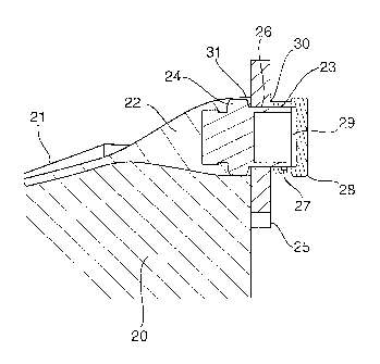
Figure 5 shows a mould 20 on which is placed a wiring component generally
referenced
21 which comprises an array of copper wires located between two layers of
hardened fibre
and filler compound. Under the vacuum conditions of production, wires and
filler paste
22 fill the rear portion of a connector 23. The connector incorporates a
flange 24 which
abuts against a connector location plate 25. The connector location plate 25
incorporates
a diameter 26 with a number of indents in order to allow the passage of
connector
projections 27. The connector location plate acts as a barrier when it is
tightly attached to
the mould 20 in order to tend to prevent filler covering the entire connector.
For the same
effect, there is also provided a connector protective cap 28 which fits
tightly over the
connectable portion of the connector. A rubber seal 29 is located on the
inside of the cap
and as the cap is secured to the connector it keeps any filler from entering
the connector
portions which necessarily are to be kept free of filler for correct
electrical connection.
Corner 30 is preferably also filled with temporary masking compound to create
an extra
seal. As can be seen from the figure at arrow 31 the composite material
surrounds the rear
portion of the connector.
CA 02638037 2008-07-22
WO 2007/083102
PCT/GB2007/000126
In figure 6, mould 20 is presented whilst being attached to plate 25 and an
upper mould
portion 32 which surrounds primarily the connector portion. Connector location
plate 25
incorporates a number of indents such as indent 33 allowing the passage of pin
27 of a
typical connector. Upper mould portion 32, plate 25 and mould 20 are joined
together by
5 screws which may be placed in bores 34, 35, 36 and 37. Threaded tunnels
are provided in
upper mould portion 32 and mould 30 to ensure a tight connection between the
three
components.
Figure 6 also illustrates a trough 38 in which the fibre, resin and wires are
placed for
10 hardening. The resulting hardened component incorporates a substantially
planar portion
with said walls such as wall 39 projecting upwards in the mould.
Figure 7 shows the trough 38 in greater detail. Before the components are
placed in the
mould it is preferred to use a release agent. Trough 38 widens out towards the
connector
portion 40.
Figure 8 is another view of the mould arrangement of figure 6. Identical
numerical
references are used for clarity.
The resulting component has a smooth and shiny surface and is preferably
comfortable at
130 degrees Celsius.
The composite material used may be obtained from Advanced Composite Material
for
example MTM57 CF0300.
The preferred insulation and conductor kinds are as follows.
For the insulation sheaths, the following are preferred: PTFE; Polyalkene
/PVDF dual
wall; Polyimide; ETFE, HSTF; FEP; TFE.
With regards to the conductor material types, the following are preferred:
Copper; Tin-
plated copper; Silver-plated copper; Nickel-plated copper; Silver-plated
copper alloy;
Nickel-plated copper alloy.
=