Note: Descriptions are shown in the official language in which they were submitted.
CA 02638151 2008-07-24
TRANSPORTING MEANS OF A CHAIR LIFT OR OF A CABLEWAY SYSTEM
The invention relates to a transporting means of a chair lift or of a cableway
system, including a frame, which is connected to a load-bearing bar coupled to
a
conveying cable, including a safety bar, including a device for closing the
safety bar,
including an energy store, including a device for charging the energy store,
and including
a blocking device for preventing the energy store from being charged, it being
possible for
the blocking device to be activated and deactivated, an opening of the safety
bar being
prevented in the active state of the blocking device.
In order to prevent the passengers from falling out of, or slipping off, a
transporting means of a chair lift or of a cableway system, the transporting
means have
closure or safety bars. The safety bars can be pivoted from a position in
which they are
located above the passengers into a position in which a crossmember extends in
front of
the passengers, over their thighs.
Safety bars which are not closed automatically upon departure from a station
of the
chair lift or of the cableway system and safety bars which are forcibly closed
in the station
by means of a rail and a cable pull are known. If, in the case of the latter
safety bars, an
overload safeguard is provided, in order to prevent passengers from being
crushed or
pinched, then, in the case of these embodiments, a correspondingly long travel
path of the
transporting means is required for the closing of the safety bar. The
traveling speed of the
transporting means cannot be too high over this travel path since, otherwise,
the closing
movement of the safety bar is executed too quickly and associated problems may
arise.
It is a disadvantage of the abovementioned safety bars that it is possible for
passengers to either not close the safety bar upon departure from the station
or to open the
safety bar en route from the boarding station to the disembarking station and
to thereby put
themselves at risk.
It is now an aspect of the invention is to provide a transporting means of the
type
mentioned above which avoids at least one of the mentioned problems.
The transporting means according to the invention is characterized in that the
blocking device prevents the safety bar from being opened over at least part
of the distance
between its fully open position and its fully closed position. This ensures
that the safety
bar remains closed throughout travel from one station to the next station.
Once the safety
bar has been closed in, or just after, a station either fully or partially, it
is not readily
1
CA 02638151 2008-07-24
possible for the safety bar to be opened again. It is only at the next station
that the safety
bar can be opened again.
In order to protect the passengers, the closing operation of the safety bar
preferably
can be halted, by a slight opposing force being applied, but the safety bar
cannot be
opened again.
In a particularly preferred embodiment of the transporting means according to
the
invention, the device for closing the safety bar and the blocking device are
advantageously
formed from the same group of interacting components. Within the context of
the
invention, however, it is also possible for the device for closing the safety
bar and the
blocking device to be formed from different groups of components.
Further details, features and advantages of the invention can be gathered from
the
following description, with reference to the accompanying drawings, which
illustrate a
preferred embodiment of the invention and in which:
Figure 1 shows a transporting means in accordance with a preferfed embodiment
of the invention, in particular a chair of a chair lift with the safety bar
open,
Figure 2 shows the chair from figure 1 with the safety bar closed,
Figure 3 shows a detail from figure 1 on a larger scale, and
Figures 4 to 9 show the detail from figure 3 in individual steps during the
closing
and opening operations of the safety bar.
Figures 1 and 2 illustrate a chair 1 of the chair lift with a safety bar 2,
having a
device 7 for activating the closing operation of the safety bar 2 and also a
device 13 for
closing the safety bar 2 and blocking the opening operation thereof. The rest
of the parts of
the chair 1 may be configured in the manner conventional in the prior art. It
will therefore
only be mentioned in general terms that the safety bar 2 is arranged on a
frame 14 which is
connected, via a joint 15, to a load-bearing bar 16, at the top end of which
is fitted a
clamping device 17 for fastening the chair I on a conveying cable 18. It is
likewise
possible, however, for the invention to be used for other forms of chairs, in
particular
couplable chairs.
Above the chair 1, and preferably in the vicinity of the clamping device 17,
the
device 7 is fastened on the load-bearing bar 16. The device 7 has a guide
roller 12 and is
raised (figure 2) when the chair 1 passes through a region with a guide
device, in particular
guide rail, which is assigned to the guide roller 12 and is arranged in the
exit region from a
station. Arranged upstream of, or in, the entry region to the station is a
further guide
2
CA 02638151 2008-07-24
device, e.g. guide rail, which moves the guide roller 12 back into the
position which is
illustrated in figure 1.
The device 7 has a carrier 30 which is mounted in a pivotable manner on the
load-
bearing bar 16 via a bearing 31. At the opposite end, the roller 12 is mounted
in a rotatable
manner on the carrier 30. The device 7 also has a toggle comprising two levers
32 and 33,
one lever 32 being mounted in a pivotable manner on the carrier 30, via a
joint 34, and the
other lever 33 being mounted in the pivotable manner on a holder of the load-
bearing bar
16, via a joint 37. The two levers 32 and 33 are connected to one another via
a joint 35.
The device 7 can assume the two end positions which are illustrated in figures
1 and 2, and
the function of which will be explained in more detail further below.
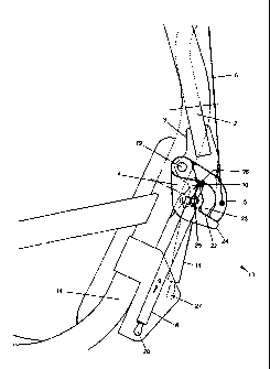
The construction according to the invention for a preferred embodiment of the
device 13 can best be seen in figure 3. The safety bar 2 has a plate-like
extension 3, by
way of which it is mounted on the frame 14 via a joint 19. A first, bottom
actuating lever 4
and a further, top actuating lever 5 are mounted at the same point. One end of
the first rod
6 is mounted on the top actuating lever 5. The rod 6 is connected, via a
Bowden cable 20,
to a second rod 21, the end of which is mounted on the device 7, more
specifically by way
of the toggle joint 35. The bottom actuating lever 4, at its free end, has a
nose 24 which
forms an abutment surface 22 for one end 23 of the extension 3 of the safety
bar 2.
Furthermore, the bottom actuating lever 4 is connected, via a joint 25, to an
energy store 8
in the form of a spring which, at its opposite end region, is mounted in a
pivotable manner
on the chair 1, for example on the frame 14 of the chair 1, by way of a joint
26. Within the
context of the invention, the spring 8 may be, for example, a pneumatic
compression
spring, as will be described hereinbelow, which is capable of being relieved
of stressing,
with its longitudinal extent being increased in the process, in arrow
direction 9. According
to the invention, the safety bar 2 is caused to close by virtue of the
pneumatic compression
spring 8 being relieved of stressing. If the pneumatic compression spring 8 is
thus relieved
of stressing in arrow direction 9, i.e. the energy store 8 is discharged, the
safety bar 2
pivots downward since the bottom actuating lever 4 is pressed against the end
23 of the
extension 3 on the safety bar 2 by way of the abutment surface 22.
In order for it to be possible to subject the pneumatic compression spring 8
to
stressing, i.e. in order to decrease its longitudinal extent counter to the
arrow direction 9,
this spring has at its top end, which is directed toward the top actuating
lever 5, a blocking
means 10 in the form of a pin which, in the first instance, has to be
depressed by the lever
3
CA 02638151 2008-07-24
since, otherwise, the pneumatic compression spring 8 is blocked against being
subjected
to stressing. This block, however, acts only against the stressing of the
pneumatic
compression spring 8, this only being the case when the pin 10 has not been
depressed. If
the pin 10, as shown in figure 3, is depressed by the top actuating lever 5,
then the
5 pneumatic compression spring 8 can be compressed, up to its fully stressed
state, until the
safety bar 2 is fully open (figure 1). According to the invention, the safety
bar 2 can thus
only be opened by virtue of the pneumatic compression spring 8 being subjected
to
stressing with the pin 10 depressed, i.e. by virtue of the energy store 8
being charged.
Instead of the abovedescribed pneumatic compression spring 8 with the pin 10,
it is also
possible to use any other suitable form of energy store 8 with a blocking
means 10 which
subjects the safety bar 2 to loading in the closing direction and at least
prevents the safety
bar 2 from being opened when the blocking means 10 is active.
Also provided is a damper 11, which is mounted in a pivotable manner, on the
one
hand, on the chair 1, for example on the frame 14 of the chair 1, via a joint
27 and, on the
other hand, on the extension 3 of the safety bar 2, via a further joint 28,
and controls the
speed of movement of the safety bar 2 during the opening and closing
operations.
The time sequence of the safety bar 2 being pivoted from the open position
into the
closed position and then back into the open position will be described with
reference to
figures 4 to 9.
Figure 4 shows the safety bar 2 in its open position according to figures 1
and 3.
The safety bar 2 assumes this position as the chair 1 passes through a
station, it being
possible for passengers to get into the chair 1 and disembark therefrom. The
pin 10 is
depressed by the top actuating lever 5, which, for its part, is pushed
downward by the
device 7, via the rod 6, the Bowden cable 20 and the rod 21 (figure 1), and
thus keeps the
pneumatic compression spring 8 in the stressed state. The nose 24 of the
bottom actuating
lever 4 butts against the end 23 of the extension 3 of the safety bar 2. In
this case, the
device 7 is located in the position which is illustrated in figure 1, and in
which the toggle
joint 35 has been pivoted beneath the joint 37, via a dead center, and butts
against an
abutment surface 36 of the holder on the load-bearing bar 16. It is thus the
case that it is no
longer possible for the rod 21 to move upward even under the force of the
stressed
pneumatic compression spring 8.
In figure 5, the safety bar 2 is still partly open. The chair 1, however, as
it exits
from the station, is passing through a region with a guide rail which pivots
in the upward
4
CA 02638151 2008-07-24
direction the guide roller 12 of the device 7 on the carrier 30. Via the lever
33, the toggle
joint 35 is rotated in the counterclockwise direction out of its dead-center
position, in
which case the rod 21 moves upward, along with the Bowden cable 20 and the rod
6, and
the top actuating lever 5 is pivoted upward.
The rod 6 thus raises the free end of the top actuating lever 5 and keeps it
in this
position, in which case the top actuating lever 5 no longer pushes the bottom
actuating
lever 4 downward, and the pneumatic compression spring 8 can begin to be
relieved of
stressing. By virtue of the pneumatic compression spring 8 being relieved of
stressing, the
bottom actuating lever 4 pivots upward and presses, by way of its abutment
surface 22,
against the end 23 of the extension 3 of the safety bar 2, in which case the
safety bar 2 is
closed.
Even in this position of the safety bar 2, the effect according to the
invention,
although the closing movement of the closing bar 2 can be stopped, counter to
the force of
the pneumatic compression spring 8, by a passenger, it is no longer possible
for the
passenger, on account of the blocking device 13, to open the safety bar 2
again counter to
the discharging action of the energy store 8, since it should only be possible
to compress
the pneumatic compression spring 8 if the pin 10 were depressed by the lever
5, is
manifested.
Figure 6 shows the safety bar 2 in its fully closed position according to
figure 2.
The bottom actuating lever 4 has been pivoted all the way upward and butts, by
way of its
nose 24, against the end 23 of the extension 3 of the safety bar 2. The top
actuating lever
5, however, does not butt against the bottom actuating lever 4. In this
position of the safety
bar 2, en route from one station to another station of the chair-lift system,
the pin 10 is not
depressed by the top actuating lever 5, in which case the pneumatic
compression spring 8
is not subjected to stressing and it is thus also the case that the safety bar
2 cannot be
opened, since the extension 3 of the safety bar 2 is blocked against such
movement by the
bottom actuating lever 4.
In figure 7, the safety bar 2 is still closed, but the chair 1, as it enters
into a station,
is moving into a region in which the guide roller 12 of the device 7, and with
it the rod 21,
the Bowden cable 20 and the rod 6, is/are moved downward by a guide rail. The
rod 6 thus
pushes the free end of the top actuating lever 5 downward, in which case the
top actuating
lever 5 depresses the pin 10 and the pneumatic compression spring 8 can be
subjected to
stressing in order for the safety bar 2 to be opened. Figure 8 shows this
position of the
5
CA 02638151 2008-07-24
device 13 upon movement past the guide rail. The guide roller 12 and thus the
rod 21, the
Bowden cable 20 and the rod 6 are moved increasingly downward. This means that
the top
actuating lever 5 is also pushed increasingly downward, during which time the
pin 10
remains depressed and the pneumatic compression spring 8 is compressed. It is
thus
possible for the safety bar 2 to be opened.
In order to provide mechanical assistance for opening the safety bar 2 into
the
position which is illustrated in figures 1 and 4, use can be made of means
which are
known from the prior art, for example a spring (not illustrated) which is
subjected to
stressing as the safety bar is closed.
Figure 9 shows the position of the device 13 during movement through a station
once the guide rail has been passed. The rod 6, which interacts with the
device 7 in order
to subject the energy store 8 to stressing and to activate the closing
operation of the safety
bar 2, remains lowered and keeps the top actuating lever 5 in position. The
top actuating
lever 5 thus blocks a pivoting movement of the bottom actuating lever 4 in the
upward
direction, this preventing the situation where the pneumatic compression
spring 8 is
relieved of stressing and the safety bar 2 is closed accidentally. The safety
bar 2, which in
the embodiment shown, rather than being provided with any positively
controlled or
mechanical assistance, is opened manually by the user, is not yet fully open
in figure 9.
It is clear from the time sequence described that, during the closing
operation and
also thereafter, the safety bar 2 is permanently blocked against executing an
opening
movement, until the pneumatic compression spring 8 is released by virtue of
the pin 10
being depressed.
In summary, an exemplary embodiment of the invention may be described as
follows.
A transporting means of a chair lift or of a cableway system has a safety bar
2, a
device 13 for closing the safety bar 2, an energy store 8 for activating the
closing device, a
device 7 for charging the energy store 8 and a blocking device 13 which
prevents the
energy store 8 from being charged. The blocking device 13 can be activated and
deactivated, opening of the safety bar 2 being prevented in the active state
of the blocking
device 13. The blocking device 13 prevents the safety bar 2 from being opened
over at
least part of the distance covered by the safety bar 2 between its fully open
position and its
fully closed position, in particular over the entire distance.
6