Language selection

Search

Patent 2638236 Summary

Third-party information liability

Some of the information on this Web page has been provided by external sources. The Government of Canada is not responsible for the accuracy, reliability or currency of the information supplied by external sources. Users wishing to rely upon this information should consult directly with the source of the information. Content provided by external sources is not subject to official languages, privacy and accessibility requirements.

Claims and Abstract availability

Any discrepancies in the text and image of the Claims and Abstract are due to differing posting times. Text of the Claims and Abstract are posted:

  • At the time the application is open to public inspection;
  • At the time of issue of the patent (grant).
(12) Patent Application: (11) CA 2638236
(54) English Title: METHOD AND MACHINE FOR PRODUCING A ROTOR OF AN ECCENTRIC SCREW PUMP
(54) French Title: METHODE ET MACHINE PERMETTANT LA PRODUCTION D'UN ROTOR D'UNE POMPE A VIS EXCENTRIQUE
Status: Deemed Abandoned and Beyond the Period of Reinstatement - Pending Response to Notice of Disregarded Communication
Bibliographic Data
(51) International Patent Classification (IPC):
  • B23B 05/12 (2006.01)
  • F04C 02/107 (2006.01)
(72) Inventors :
  • JAEGER, SEBASTIAN (Germany)
  • WEINHOEFER, WILLI (Germany)
(73) Owners :
  • ARTEMIS KAUTSCHUK- UND KUNSTSTOFF-TECHNIK GMBH
(71) Applicants :
  • ARTEMIS KAUTSCHUK- UND KUNSTSTOFF-TECHNIK GMBH (Germany)
(74) Agent: SMART & BIGGAR LP
(74) Associate agent:
(45) Issued:
(22) Filed Date: 2008-07-24
(41) Open to Public Inspection: 2010-01-24
Examination requested: 2011-07-18
Availability of licence: N/A
Dedicated to the Public: N/A
(25) Language of filing: English

Patent Cooperation Treaty (PCT): No

(30) Application Priority Data: None

Abstracts

English Abstract


The present invention relates to a method and a machine for
producing a rotor of an eccentric screw pump, with which or in
which the shape of the rotor is produced by a peeling process
followed by a smoothing process of the surface. The object of the
invention is to make the smoothing process less time-consuming and,
in addition, more cost effective with this method or with this
machine. This object is solved with a method in which the
smoothing process is accomplished by smooth-rolling. The machine
for carrying out the method has a machine bed (3) on which a
peeling head (9) and a smoothing head (7) are arranged so as to be
axially movable for processing the rotor (2).


Claims

Note: Claims are shown in the official language in which they were submitted.

-5-
Claims
1. A method for producing a rotor of an eccentric screw pump in
which the shape of the rotor is produced by a peeling process
followed by a smoothing process of the surface, characterized
in that the smoothing process is accomplished by smooth-
rolling.
2. A machine for carrying out the method according to claim 1,
having a machine bed (3) on which a peeling head (9) and a
smoothing head (7) are arranged so as to be axially movable
for processing the rotor (2).
3. The machine according to claim 2, characterized in that
peeling head (9) and smoothing head (7) are arranged on one
carriage (15).
4. The machine according to claim 2, characterized in that
peeling head (9) and smoothing head (7) are arranged on
separate carriages (6, 8).
5. The machine according to any one of the preceding claims 2 to
4, characterized in that the roll bodies (13) of the smoothing
head (7) are acted upon by hydraulic cylinders (14).

Description

Note: Descriptions are shown in the official language in which they were submitted.


CA 02638236 2008-07-24
Method And Machine For Producing A Rotor Of An
Eccentric Screw Pump
The present invention relates to a method and a machine for
producing a rotor of an eccentric screw pump according to the
preamble of claim 1 and claim 2, respectively.
Rotors of eccentric screw pumps consist of a hard material, for
example of case-hardened steel, and run in a stator lined with an
elastomer. To obtain an effective seal between rotor and stator
during operation and to minimize, wear, the surface of the rotor
must be smooth.
Usually, after a metal-cutting shaping which generally takes place
by a peeling process, a rotor is ground to its finished size by
means of belt grinding and the surface is then fine-ground and
optionally also polished. This production method is very time-
consuming and cost-intensive.
DE 299 04 463 U1 describes a method in which, after a metal-cutting
shaping to smooth its surface, the rotor is placed in a bed
consisting of gliding abrasives arranged in a grinding emulsion.
The grinding process then takes place through the movement of the
bed. A grinding process of this type is still costly and time-
consuming.
DE 196 33 984 Al describes a method in which a metal-cutting
shaping of the rotor is omitted. To be able to produce the rotor
more inexpensively, master pattern or shaping techniques are used.
In this case, a blank of the rotor is produced by casting or drop-
forging. As its surface is still very rough, it must be finished.
This is accomplished by drawing the rotor through a nozzle or

CA 02638236 2008-07-24
- 2 -
pressing it through said nozzle. Consequently, the surface of the
rotor is smoothed and its cross-sectional measurement
simultaneously calibrated. Thus, in this case, the surface of the
rotor is smoothed with aid of a shaping technique.
The object of the present invention is to provide a generic method
and a machine with which the smoothing process can be carried out
in a less time-consuming manner and, in addition, cost-effectively.
According to the invention, this object is solved with a method
which has the features of claim 1 and with a machine according to
claim 2.
Therefore, with the method according to the invention, the
finishing of the surface of the rotor is accomplished by smooth
rolling. The technology of smooth rolling for the finishing of
surfaces has been part of the general prior art for a long time.
Despite the sufficiently known advantages associated therewith -
slight peak-to-valley height and increase in hardness due to cold
work-hardening - this technology has surprisingly not been used to
date in the manufacture of a rotor for an eccentric screw pump.
Time can be saved by smooth-rolling in comparison to the finishing
by grinding.
A machine for carrying out the method according to the invention is
constructed similar to a turning machine. It has a machine bed on
which a peeling head and a smoothing head are arranged so as to be
axially movable. The peeling head and the smoothing head can
thereby be arranged either on one or on separate carriages.
Furthermore, it is advantageous if the roll body of the smoothing
head be acted upon by hydraulic cylinders in order to control the
contact pressure.

CA 02638236 2008-07-24
- 3 -
The invention will be described in greater detail in the following
with reference to two embodiments. The attached drawings show:
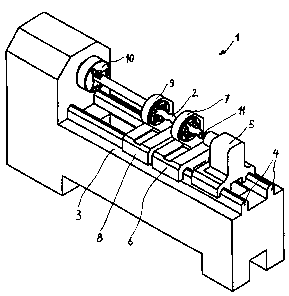
Fig. 1 a perspective view on a machine for peeling and smooth-
rolling a rotor of an eccentric screw pump according to
a first embodiment,
Fig. 2 a side view of a machine for peeling and smooth-rolling
a rotor of an eccentric screw pump according to a second
embodiment,
Fig. 3 a side view of a smoothing head, and
Fig. 4 a side view of a peeling head.
The machine 1 shown in the drawing for producing rotors 2 for
eccentric screw pumps is constructed similar to a turning machine.
It has a bed 3 with two parallel guide rails 4 on which a tailstock
5, a carriage 15 (Fig. 1) or two carriages 6 and 8 (Fig. 2) for a
smoothing head 7 and for a peeling head 9 are arranged so as to be
longitudinally movable. The rotor 2 or its blank is clamped in a
chuck 10 on its one end and supported on the tailstock 5 on its
other end, which has a centering stock 11 for it which engages in
a centre bore placed in the rotor 2 at the front end. Instead of
the tailstock 5, a bush for the radial support of the rotor 2 can
also be used. Steady rests can also be used.
The structure of the peeling head 9 and smoothing head 7
corresponds to the prior art. In the embodiments of the invention,
the peeling head 9 has six peeling knives 12 which are each
arranged at a distance of 60 from one another.
In this embodiment, three spherical roll bodies 13, which are each

CA 02638236 2008-07-24
- 4 -
arranged at a distance of 1200 from one another, can be used in the
smoothing head 7. The roll bodies 13 on the rotor 2 are positioned
via hydraulic cylinders 14 which ensure a uniform and sufficient
contact pressure of the roll bodies 13 on the surface of the rotor
2 (see arrow F in Fig. 3).
In the embodiment shown in Fig. 1, the peeling head 9 and smoothing
head 7, as described above, are arranged on separate carriages 8
and 6, as a result of which they can be moved separately. To
produce the rotor 2, the peeling head 9 is first moved from the
tailstock 5 toward the chuck 10, as a result of which the exact
contour of the rotor 2 is produced. The smoothing head 7 is then
moved toward the chuck 10, as a result of which a smoothing of the
surface of the rotor 2 is obtained. Once these two procedural
steps have been completed, the peeling head 9 and smoothing head 7
are returned to their initial position.
In the embodiment according to Fig. 2, the peeling head 9 and
smoothing head 7 are arranged on one carriage 15. Consequently,
they can be moved together. The processing time of the rotor 2 can
be further reduced by this arrangement in comparison to the first
embodiment.

Representative Drawing
A single figure which represents the drawing illustrating the invention.
Administrative Status

2024-08-01:As part of the Next Generation Patents (NGP) transition, the Canadian Patents Database (CPD) now contains a more detailed Event History, which replicates the Event Log of our new back-office solution.

Please note that "Inactive:" events refers to events no longer in use in our new back-office solution.

For a clearer understanding of the status of the application/patent presented on this page, the site Disclaimer , as well as the definitions for Patent , Event History , Maintenance Fee  and Payment History  should be consulted.

Event History

Description Date
Application Not Reinstated by Deadline 2014-07-24
Time Limit for Reversal Expired 2014-07-24
Inactive: Abandoned - No reply to s.30(2) Rules requisition 2013-09-26
Deemed Abandoned - Failure to Respond to Maintenance Fee Notice 2013-07-24
Inactive: S.30(2) Rules - Examiner requisition 2013-03-26
Letter Sent 2011-08-03
All Requirements for Examination Determined Compliant 2011-07-18
Request for Examination Requirements Determined Compliant 2011-07-18
Request for Examination Received 2011-07-18
Application Published (Open to Public Inspection) 2010-01-24
Inactive: Cover page published 2010-01-24
Inactive: IPC assigned 2009-09-10
Inactive: First IPC assigned 2009-09-10
Inactive: IPC assigned 2009-09-10
Correct Applicant Requirements Determined Compliant 2009-08-26
Inactive: Filing certificate - No RFE (English) 2009-08-26
Inactive: Applicant deleted 2009-08-26
Inactive: Correspondence - Formalities 2009-07-15
Inactive: Correspondence - Formalities 2009-03-10
Inactive: Filing certificate correction 2008-11-07
Inactive: Filing certificate - No RFE (English) 2008-09-23
Application Received - Regular National 2008-09-23

Abandonment History

Abandonment Date Reason Reinstatement Date
2013-07-24

Maintenance Fee

The last payment was received on 2012-05-14

Note : If the full payment has not been received on or before the date indicated, a further fee may be required which may be one of the following

  • the reinstatement fee;
  • the late payment fee; or
  • additional fee to reverse deemed expiry.

Patent fees are adjusted on the 1st of January every year. The amounts above are the current amounts if received by December 31 of the current year.
Please refer to the CIPO Patent Fees web page to see all current fee amounts.

Fee History

Fee Type Anniversary Year Due Date Paid Date
Application fee - standard 2008-07-24
MF (application, 2nd anniv.) - standard 02 2010-07-26 2010-07-15
MF (application, 3rd anniv.) - standard 03 2011-07-25 2011-07-15
Request for examination - standard 2011-07-18
MF (application, 4th anniv.) - standard 04 2012-07-24 2012-05-14
Owners on Record

Note: Records showing the ownership history in alphabetical order.

Current Owners on Record
ARTEMIS KAUTSCHUK- UND KUNSTSTOFF-TECHNIK GMBH
Past Owners on Record
SEBASTIAN JAEGER
WILLI WEINHOEFER
Past Owners that do not appear in the "Owners on Record" listing will appear in other documentation within the application.
Documents

To view selected files, please enter reCAPTCHA code :


To view images, click a link in the Document Description column. To download the documents, select one or more checkboxes in the first column and then click the "Download Selected in PDF format (Zip Archive)" or the "Download Selected as Single PDF" button.

List of published and non-published patent-specific documents on the CPD .

If you have any difficulty accessing content, you can call the Client Service Centre at 1-866-997-1936 or send them an e-mail at CIPO Client Service Centre.


Document
Description 
Date
(yyyy-mm-dd) 
Number of pages   Size of Image (KB) 
Description 2008-07-23 4 146
Abstract 2008-07-23 1 20
Claims 2008-07-23 1 26
Drawings 2008-07-23 3 54
Representative drawing 2009-12-30 1 10
Filing Certificate (English) 2008-09-22 1 157
Filing Certificate (English) 2009-08-25 1 166
Reminder of maintenance fee due 2010-03-24 1 115
Acknowledgement of Request for Examination 2011-08-02 1 177
Courtesy - Abandonment Letter (Maintenance Fee) 2013-09-17 1 172
Courtesy - Abandonment Letter (R30(2)) 2013-11-20 1 164
Correspondence 2008-11-06 2 112
Correspondence 2009-03-09 1 50
Correspondence 2009-07-14 1 48
Fees 2011-07-14 1 66