Language selection

Search

Patent 2638663 Summary

Third-party information liability

Some of the information on this Web page has been provided by external sources. The Government of Canada is not responsible for the accuracy, reliability or currency of the information supplied by external sources. Users wishing to rely upon this information should consult directly with the source of the information. Content provided by external sources is not subject to official languages, privacy and accessibility requirements.

Claims and Abstract availability

Any discrepancies in the text and image of the Claims and Abstract are due to differing posting times. Text of the Claims and Abstract are posted:

  • At the time the application is open to public inspection;
  • At the time of issue of the patent (grant).
(12) Patent: (11) CA 2638663
(54) English Title: METHOD TO INCREASE GAS MASS FLOW INJECTION RATES TO GAS STORAGE CAVERNS USING LNG
(54) French Title: PROCEDE PERMETTANT D'AUGMENTER LE DEBIT D'INJECTION MASSIQUE DE GAZ APPLIQUE AUX CAVITES DE STOCKAGE DE GAZ AU MOYEN DE GAZ NATUREL LIQUEFIE
Status: Granted and Issued
Bibliographic Data
(51) International Patent Classification (IPC):
  • B65G 5/00 (2006.01)
  • F17C 5/00 (2006.01)
  • F17C 13/00 (2006.01)
  • F28F 27/00 (2006.01)
(72) Inventors :
  • LOURENCO, JOSE (Canada)
  • MILLAR, MACKENZIE (Canada)
(73) Owners :
  • 1304342 ALBERTA LTD.
  • 1304338 ALBERTA LTD.
(71) Applicants :
  • 1304342 ALBERTA LTD. (Canada)
  • 1304338 ALBERTA LTD. (Canada)
(74) Agent: NATHAN V. WOODRUFFWOODRUFF, NATHAN V.
(74) Associate agent:
(45) Issued: 2015-01-13
(22) Filed Date: 2007-07-20
(41) Open to Public Inspection: 2009-01-20
Examination requested: 2012-05-23
Availability of licence: N/A
Dedicated to the Public: N/A
(25) Language of filing: English

Patent Cooperation Treaty (PCT): No

(30) Application Priority Data: None

Abstracts

English Abstract

A method to increase gas mass flow loading rates to a gas storage cavern includes using liquid natural gas (LNG) to cool natural gas in a natural gas flow line upstream of a compressor used to compress gas for storage in to a gas storage cavern.


French Abstract

Une méthode permettant d'augmenter les débits d'injection massique de gaz appliqués aux cavités de stockage de gaz comprend l'utilisation du gaz naturel liquéfié (GNL) pour refroidir le gaz naturel dans un flux de conduite d'écoulement de gaz d'un compresseur utilisé pour comprimer le gaz en vue du stockage dans une cavité de stockage de gaz.

Claims

Note: Claims are shown in the official language in which they were submitted.

4
What is Claimed is:
1. A method for gas injection to a gas storage cavern, comprising:
positioning at the gas storage cavern a tank of LNG, a gas compressor and a
heat
exchanger;
connecting the tank of LNG to a first flow line connected to a first flow path
of the heat
exchanger and also to a second flow line leading directly to the gas storage
cavern, the selection
of the first flow line or the second flow line being controlled by selectively
opening and closing a
series of valves;
connecting an outlet of the first flow path of the heat exchanger to a third
flow line
connected to a mixer positioned on the compressed gas stream line exiting the
gas compressor to
the gas storage cavern and also to the second flow line, the selection of the
third flow line or the
second flow line being controlled by selectively opening and closing a series
of valves;
when the gas compressor is in operation, passing LNG from the tank along the
first flow
line to the heat exchanger, through the first flow path of the heat exchanger
and discharging
LNG exiting the first flow path of the heat exchanger to the third flow line
connected to the
mixer positioned on the compressed gas stream line exiting the gas compressor
into the gas
storage cavern and passing natural gas from a natural gas flow line through a
second flow path of
the heat exchanger; and
passing natural gas exiting the second flow path of the heat exchanger through
the gas
compressor which injects the natural gas into the gas storage cavern;
monitoring at least one of temperature or pressure of the gas storage cavern;
and
when the gas compressor is not in operation, pumping LNG from the tank of LNG
along
the second flow line leading directly to the gas storage cavern to maintain a
desired temperature
or pressure.

Description

Note: Descriptions are shown in the official language in which they were submitted.


CA 02638663 2008-07-20
1
TITLE:
Method to increase gas mass flow injection rates to gas storage caverns using
LNG.
FIELD
The present invention relates to a method of increasing gas mass flow
injection rates
to gas storage caverns using LNG.
BACKGROUND
Natural gas is traditionally stored in a gaseous form in large volume salt
caverns and
aquifers to meet peak demand and ensure a secure supply. The gas is added to
storage by
compression, resulting in an increment in cavern temperature and an increment
in cavern
pressure. These increments in pressure and temperature in the cavern decrease
the rate at
which gas can be added to the cavern..
SUMMARY
A method to increase gas mass flow injection rates to a gas storage cavern,
includes
using liquid natural gas (LNG) to cool natural gas in a natural gas flow line
upstream of a
compressor used to compress gas for storage in to a gas storage cavern.
BRIEF DESCRIPTION OF THE DRAWINGS
These and other features of the invention will become more apparent from the
following description in which reference is made to the appended drawings, the
drawings are
for the purpose of illustration only and are not intended to in any way limit
the scope of the
invention to the particular embodiment or embodiments shown, wherein:
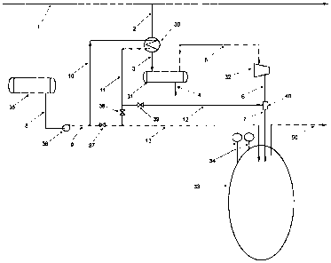
FIG. 1 is a schematic diagram that depicts an embodiment of the teachings
contained
herein.
FIG. 2 is a variation on the embodiment shown in FIG. 1.

CA 02638663 2013-10-08
2
DETAILED DESCRIPTION
The preferred method to increase mass flow gas injection rates will now be
described
with reference to FIGURE 1.
Gas is supplied from main pipeline stream 1. The gas to storage is routed
through line
2 to exchanger 30 where it is cooled by LNG. The cooler gas exits exchanger 30
via stream 3
to knock out drum 31, to remove any condensate and debris present in the
stream. The
condensate is removed through stream 4. The cold gas is routed through stream
5 to
compressor 32 for injection into cavern 33 via stream 6. LNG is supplied from
tank 35 and is
routed through line 8 to pump 36 where it is pressurized and routed through
line 9. The LNG
is routed through line 10 to exchanger 30, to cool the gas to storage and
exits the exchanger
through line 11. The gas in stream 11 is colder than compressed gas in stream
6. The gas can
then be routed through valve 39 and line 12 to mix directly with stream 6 in
mixer 40,
increasing the gas density of gas stream 7 to storage 33. The option of
routing stream 11
through valve 38 and line 13 directly to storage cavern 33 is available. The
operating
conditions for the cavern are monitored by pressure and temperature sensors
34. The
objective is to increase the gas injection rate of compressor 32 by lowering
the temperature of
the gas suction line to the compressor, making the gas denser, thus increasing
the mass flow
rate and also decreasing the compressor outlet temperature. The compressor
outlet
temperature can be further decreased by direct mixing of stream 12 with stream
6. For every
incremental decrease in the temperature of gas entering cavern 33, the amount
of gas cavern
33 is capable of storing increases. If it is desirable to further decrease the
temperature of
cavern 33, the option of routing stream 11 through valve 38 and line 13
directly to storage
cavern 33 is followed.
A variation will now be described with reference to FIG. 2.
Gas is supplied from main pipeline stream 1. The gas to storage is routed
through line
2 to exchanger 30 where it is cooled by LNG. The cooler gas exits exchanger 30
via stream 3
to knock out drum 31 to remove any condensate and debris present in the
stream. The
condensate is removed through stream 4. The cold gas is routed through stream
5 to
compressor 32, where it is compressed and delivered through line 6 to
exchanger 41 where

CA 02638663 2008-07-20
3
it is cooled. The compressed and cooled stream 7 mixes with stream 11 and is
stored
through line 12 into gas cavern storage 33. LNG is supplied from tank 35 and
is routed
through line 8 to pump 36 where it is pressurized and routed through line 9.
The LNG is
routed to exchanger 30, to cool the gas to storage and exits the exchanger
through line 10.
The gas in stream 10 is colder than compressed gas in stream 6. The gas stream
10 enters
exchanger 41 to cool the compressor discharge gas. The gas can then be routed
through
valve 39 to mix directly with stream 7 to storage 33 through line 12. The
option of routing
stream 11 through valve 38 and line 13 directly to storage cavern 33 is
available. The
operating conditions for the cavern are monitored by pressure and temperature
sensors 34.
The objective is to increase the gas mass flow injection rate of compressor 32
by
lowering the temperature of the gas suction line to the compressor, making the
gas denser,
thus increasing the mass flow rate whilst also decreasing the compressor
outlet
temperature. The compressor outlet temperature is further decreased by
indirect mixing
of stream 10 with stream 6 thus further improving the power requirements for
compression. The described embodiment of Fig.3 provides the ability for gas
cavern
operators to increase the mass flow gas injection rates to cavern storage.
The stored gas exits the cavern via stream 50 to meet demand.
In this patent document, the word "comprising" is used in its non-limiting
sense to
mean that items following the word are included, but items not specifically
mentioned are not
excluded. A reference to an element by the indefinite article "a" does not
exclude the
possibility that more than one of the element is present, unless the context
clearly requires that
there be one and only one of the elements.
It will be apparent to one skilled in the art that modifications may be made
to the
illustrated embodiments without departing from scope of the Claims.

Representative Drawing
A single figure which represents the drawing illustrating the invention.
Administrative Status

2024-08-01:As part of the Next Generation Patents (NGP) transition, the Canadian Patents Database (CPD) now contains a more detailed Event History, which replicates the Event Log of our new back-office solution.

Please note that "Inactive:" events refers to events no longer in use in our new back-office solution.

For a clearer understanding of the status of the application/patent presented on this page, the site Disclaimer , as well as the definitions for Patent , Event History , Maintenance Fee  and Payment History  should be consulted.

Event History

Description Date
Inactive: COVID 19 - Deadline extended 2020-07-16
Common Representative Appointed 2019-10-30
Grant by Issuance 2015-01-13
Inactive: Cover page published 2015-01-12
Inactive: Final fee received 2014-10-17
Pre-grant 2014-10-17
Notice of Allowance is Issued 2014-09-11
Letter Sent 2014-09-11
Notice of Allowance is Issued 2014-09-11
Inactive: QS passed 2014-08-27
Inactive: Approved for allowance (AFA) 2014-08-27
Amendment Received - Voluntary Amendment 2014-05-26
Letter Sent 2013-12-12
Inactive: S.30(2) Rules - Examiner requisition 2013-11-26
Inactive: Report - No QC 2013-11-18
Amendment Received - Voluntary Amendment 2013-10-08
Inactive: S.30(2) Rules - Examiner requisition 2013-04-10
Letter Sent 2012-05-30
Request for Examination Requirements Determined Compliant 2012-05-23
All Requirements for Examination Determined Compliant 2012-05-23
Request for Examination Received 2012-05-23
Inactive: Office letter 2011-05-16
Inactive: Cover page published 2009-01-21
Inactive: IPC assigned 2009-01-20
Application Published (Open to Public Inspection) 2009-01-20
Inactive: First IPC assigned 2009-01-20
Inactive: IPC assigned 2009-01-20
Inactive: IPC assigned 2009-01-12
Inactive: IPC removed 2009-01-12
Inactive: IPC assigned 2009-01-12
Inactive: Filing certificate - No RFE (English) 2008-10-02
Filing Requirements Determined Compliant 2008-10-02
Application Received - Regular National 2008-10-02

Abandonment History

There is no abandonment history.

Maintenance Fee

The last payment was received on 2014-06-24

Note : If the full payment has not been received on or before the date indicated, a further fee may be required which may be one of the following

  • the reinstatement fee;
  • the late payment fee; or
  • additional fee to reverse deemed expiry.

Please refer to the CIPO Patent Fees web page to see all current fee amounts.

Owners on Record

Note: Records showing the ownership history in alphabetical order.

Current Owners on Record
1304342 ALBERTA LTD.
1304338 ALBERTA LTD.
Past Owners on Record
JOSE LOURENCO
MACKENZIE MILLAR
Past Owners that do not appear in the "Owners on Record" listing will appear in other documentation within the application.
Documents

To view selected files, please enter reCAPTCHA code :


To view images, click a link in the Document Description column. To download the documents, select one or more checkboxes in the first column and then click the "Download Selected in PDF format (Zip Archive)" or the "Download Selected as Single PDF" button.

List of published and non-published patent-specific documents on the CPD .

If you have any difficulty accessing content, you can call the Client Service Centre at 1-866-997-1936 or send them an e-mail at CIPO Client Service Centre.


Document
Description 
Date
(yyyy-mm-dd) 
Number of pages   Size of Image (KB) 
Abstract 2008-07-20 1 7
Description 2008-07-20 3 122
Drawings 2008-07-20 2 18
Claims 2008-07-20 2 54
Representative drawing 2009-01-09 1 5
Cover Page 2009-01-21 1 31
Description 2013-10-08 3 123
Claims 2013-10-08 1 20
Claims 2014-05-26 1 38
Cover Page 2014-12-18 1 31
Maintenance fee payment 2024-06-18 1 26
Filing Certificate (English) 2008-10-02 1 157
Reminder of maintenance fee due 2009-03-23 1 112
Reminder - Request for Examination 2012-03-21 1 118
Acknowledgement of Request for Examination 2012-05-30 1 174
Commissioner's Notice - Application Found Allowable 2014-09-11 1 161
Maintenance fee payment 2023-07-12 1 26
Fees 2013-06-21 1 155
Correspondence 2008-10-02 1 57
Correspondence 2009-03-23 1 40
Fees 2009-06-16 1 30
Fees 2010-04-22 1 29
Correspondence 2011-03-31 3 155
Correspondence 2011-05-16 1 20
Correspondence 2011-05-16 1 35
Correspondence 2014-10-17 1 33
Maintenance fee payment 2017-07-04 1 25
Maintenance fee payment 2020-07-20 1 26
Maintenance fee payment 2021-07-20 1 26
Maintenance fee payment 2022-07-20 1 26