Language selection

Search

Patent 2638666 Summary

Third-party information liability

Some of the information on this Web page has been provided by external sources. The Government of Canada is not responsible for the accuracy, reliability or currency of the information supplied by external sources. Users wishing to rely upon this information should consult directly with the source of the information. Content provided by external sources is not subject to official languages, privacy and accessibility requirements.

Claims and Abstract availability

Any discrepancies in the text and image of the Claims and Abstract are due to differing posting times. Text of the Claims and Abstract are posted:

  • At the time the application is open to public inspection;
  • At the time of issue of the patent (grant).
(12) Patent Application: (11) CA 2638666
(54) English Title: INFLATABLE KITE WITH VENTS
(54) French Title: CERF-VOLANT GONFLABLE AVEC PRISES D'AIR
Status: Withdrawn
Bibliographic Data
(51) International Patent Classification (IPC):
  • A63H 27/08 (2020.01)
(72) Inventors :
  • HARRINGTON, ROSS D. (Canada)
(73) Owners :
  • OCEAN RODEO SPORTS INC.
(71) Applicants :
  • OCEAN RODEO SPORTS INC. (Canada)
(74) Agent: J. GORDON THOMSONTHOMSON, J. GORDON
(74) Associate agent:
(45) Issued:
(22) Filed Date: 2008-08-12
(41) Open to Public Inspection: 2009-02-13
Availability of licence: N/A
Dedicated to the Public: N/A
(25) Language of filing: English

Patent Cooperation Treaty (PCT): No

(30) Application Priority Data:
Application No. Country/Territory Date
60/935,432 (United States of America) 2007-08-13

Abstracts

English Abstract


An inflatable kite uses an inflatable tubular member as a leading
edge. The wing is a membrane attached to the front of the leading
edge to form a high camber for high lift. Vents in the wing fabric
have flaps on them to form nozzles which, when wind is blowing
over the kite, cause high pressure air under the kite to exhaust to
the top surface of the kite and extend conditions of near laminar
flow towards the trailing edge. This increases kite stability and
improves stall characteristics.


Claims

Note: Claims are shown in the official language in which they were submitted.

What is claimed is:
1. An inflatable kite comprising:
a. an aerodynamic body, said body comprising a wing
membrane having a top surface, a bottom surface, a left
tip, a right tip and a plurality of vents for venting high
pressure air from said membrane bottom surface to said
membrane top surface;
b. a leading edge comprising an inflatable tubular member;
c. a trailing edge; and,
d. a plurality of ribs disposed between said leading edge and
said trailing edge for supporting a desired geometry of
said wing membrane;
e. wherein, during flight, said venting of high pressure air
extends laminar or near laminar flow conditions on the
top surface of the wing membrane from said plurality of
vents to said trailing edge thereby improving stall
characteristics of said kite.

2. The kite of claim 1 wherein the wing membrane has a
generally elliptical shape.
3. The kite of claim 1 wherein the wing membrane comprises a
flexible and substantially non-porous material.
4. The kite of claim 3 wherein the wing membrane is a single
piece of material.
5. The kite of claim 1 wherein each vent of said plurality of
vents is generally rectangular and disposed approximately
parallel to the inflatable tubular member.
6. The kite of claim 5 wherein the plurality of vents is disposed
approximately between mid-way and two thirds the distance
between the leading edge and the trailing edge.
2

7. The kite of claim 5 wherein the plurality of vents is disposed
approximately two-thirds the distance between the leading
edge and the trailing edge.
8. The kite of claim 6 wherein the plurality of vents comprises a
first vent disposed within an upper left segment of the wing
membrane and a second vent disposed within an upper right
segment of the wing membrane.
9. The kite of claim 8 wherein said first and second vents
comprise a leading edge and a trailing edge parallel to the
inflatable tubular member and a left side and right side edge
parallel to the left and right tips respectively.
10. The kite of claim 9 wherein the first vent and the second vent
are covered with a fabric having a large geometric porosity.
11. The kite of claim 10 wherein said fabric is a mesh fabric.
3

12. The kite of claim 10 wherein the fabric is a perforated fabric.
13. The kite of claim 10 wherein the first and second vents
comprise a portion of wing that is reinforced and perforated
for desired air flow.
14. The kite of claim 9 wherein the first vent and the second vent
are voids.
15. The kite of claim 10 wherein during flight the first vent and
the second vent permit high pressure air under the wing to
escape to the upper surface of the wing and flow rear-ward
along the upper surface as laminar or near laminar flow
thereby improving aerodynamic performance of the wing at
high attack angles.
16. The kite of claim 15 wherein each of the first and second
vents include a flap member fixed to their respective vent
leading edges, left tips and right tips thereby forming a
4

nozzle having an open trailing end for directing moving air
from the lower surface of the wing to the upper surface of
the wing and rearward at a velocity sufficient to create
laminar or near laminar flow conditions on the upper surface
of the wing for improved aerodynamic performance at high
attack angles.
17. An inflatable kite comprising:
a. an aerodynamic body, said body comprising a generally
elliptical wing membrane comprising flexible and
substantially non-porous material having a top membrane
surface, a bottom membrane surface, a left tip, a right tip;
b. a plurality of generally rectangular vents disposed within
the wing membrane, generally parallel to the inflatable
tubular member and approximately two thirds the
distance between the leading edge and the trailing edge
wherein said vents are adapted for venting high pressure
air from said wing bottom surface to said wing top
surface;

c. a leading edge comprising an inflatable tubular member;
d. a trailing edge; and,
e. a plurality of generally parallel ribs disposed between said
leading edge and said trailing edge for supporting a
desired geometry of said wing membrane.
1$. An inflatable kite comprising:
a. an aerodynamic body, said body comprising a generally
elliptical wing membrane comprising flexible and
substantially non-porous material having a top membrane
surface, a bottom membrane surface, a centre line, a left
tip and a right tip;
b. a leading edge comprising an inflatable tubular member;
c. a trailing edge;
d. a plurality of generally equally spaced and parallel ribs
disposed between said leading edge and said trailing edge
for supporting a desired geometry of said wing membrane
and for creating an equal number of wing segments on
6

each side of said centre line including an upper left
segment and an upper right segment; and,
e. a first vent disposed within said upper left segment and a
second vent disposed within said upper right segment.
19. The kite of claim 18 wherein said first and second vents
comprise a leading edge and a trailing edge parallel to the
inflatable tubular member and a left side and right side edge
parallel to the left and right tips respectively.
20. The kite of claim 19 wherein each of the first and second
vents include a flap member fixed to their respective opening
leading edges, left tips and right tips thereby forming a
nozzle having an open trailing end for directing moving air
from the lower surface of the wing to the upper surface of
the wing and rearward at a velocity sufficient to extend near
laminar flow conditions on the upper surface of the wing for
improved aerodynamic performance at high attack angles.
7

Description

Note: Descriptions are shown in the official language in which they were submitted.


CA 02638666 2008-08-12
Title of the Invention
Inflatable Kite with Vents
Cross-Reference to Related Applications
This application claims the benefit of United States Provisional Patent
Application #60/935,432 filed in the USPTO on August 13, 2007.
Background of the Invention
Field of the Invention
This invention relates to kites used in the sport of kite boarding and more
particularly an inflatable kite having vents.
Discussion of Prior Art
Kite boarding is a sport where an individual is pulled along the top of the
water, snow or land while standing on a small board (approx. 48" x 16" x
Y2") by a kite (approx. 5 - 20 sq. meters). Kite boarding is a fast growing
sport worldwide. Very high speeds can be reached on these boards and
1

CA 02638666 2008-08-12
they can jump many meters into the air even off a small wave due to the
power generated by the kites. Kites now have the ability to have their
angle of attack controlled by the rider but this can at times result in the
kite stalling because the kite wing is set at too high of an angle of attack
to the wind.
Therefore there is a need to improve the aerodynamic stability of the kite
at high angles of attack so that the kite does not stall and crash.
Summary of the Invention
To solve the problem with unstable airflow over the top surface of the
kite wing membrane at high angles of attack, vents have been introduced
on an inflatable kite. When vents are placed in a predetermined location
on the wing membrane they can delay the onset of stalling by allowing
higher pressure air on the underside of the wing membrane to be
released onto the top surface of the wing membrane, near the region
where the air flow is separating from the top surface of the membrane,
2

CA 02638666 2008-08-12
and hence keep the air flow attached. This increases the kite's overall
wind range as well as making it easier for the rider to fly.
One embodiment of my invention comprises an aerodynamic body
comprising a generally elliptical wing formed by a flexible low porosity
membrane having a top surface, a bottom surface, a left tip, a right tip
and a plurality of vents for venting air from the wing bottom surface to
the wing top surface. The wing has a leading edge comprising an
inflatable tubular member. The wing also has a trailing edge; and, a
plurality of ribs disposed between the leading edge and the trailing edge
for supporting a desired geometry of the wing.
Brief Description of the Drawings
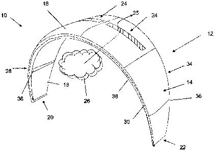
Figure 1 is a view of a kite body of one embodiment of the invention.
Figure 2 is a cross-sectional view of a kite body of another embodiment
of the invention.
Figure 3 is a view of the same embodiment of Figure 1.
Figure 4 is two views of vent mesh of embodiments of the invention.
3

CA 02638666 2008-08-12
Figure 5 is a view of a kite body including fabric covers on the vents.
Detailed Description
Referring to Figure 1, my invention is a kite 10 of the type used in kite
boarding and related sports. A person familiar with the sport will realize
that the drawings accompanying this submission are of the kite only.
Additional equipment, not illustrated in this submission, would include
kite rigging, a kite board, a control bar and a harness for the user. The
kite 10 of my invention comprises an aerodynamic body 12. The
aerodynamic body 12 comprises a generally elliptical wing 14 comprising
a low porosity membrane having a top surface 16, a bottom surface 18, a
left tip 20, a right tip 22 and a plurality of vents 24 for venting 25 high
pressure air 26 from underneath the wing bottom surface 18 to the wing
top surface 16. The body of my invention further comprises a leading
edge 28 comprising an inflatable tubular member 30. There is also a
trailing edge 34 opposite the leading edge 28. To provide a desired
geometric form and structural support to the wing there is included in my
4

CA 02638666 2008-08-12
invention a plurality of parallel ribs 36 disposed between the leading
edge 28 and the trailing edge 34 of the wing 14.
The inflatable tubular member has a radial length as shown by dashed
line 38 connecting said left tip 20 and the right tip 22.
Refer now to Figure 2 and Figure 5. Figure 5 is the same embodiment as
Figure 1 with flap members 106 and 108. As shown in Figure 2, which is
a cross-section of the wing of one embodiment of the invention shown in
Figure 5 at A-A, the generally elliptical wing 14 is fixed to the leading
edge 28 at a wing fixing point 56 that is on the front 42 of the outer
surface 40 of the inflatable tubular member.
Referring to Figure 3, which is the same embodiment as in Figure 1, kite
wing 14 has two generally rectangular vents 80 and 82 disposed parallel
to the inflatable tubular member 30 from approximately midway to two
thirds the distance between the leading edge 28 and the trailing edge 34.
In other embodiments of the invention there can be more or fewer vents
5

CA 02638666 2008-08-12
depending on the desired aerodynamic properties of the wing. In the
embodiment illustrated in Figure 3, the wing has a first opening 80
disposed within the upper left segment 72 of the wing and a second
opening 82 disposed within the upper right segment of the wing 74. The
first and second vents comprise a leading edge 86 and a trailing edge 88
generally parallel to the inflatable tubular member 30 and a left side edge
90 and right side edge 92 generally parallel to the left 20 and right tips
22 respectively. The vents are covered with a fabric having a large
geometric porosity that permits pressurized air 26 flow from the bottom
of the wing to the top of the wing 25.
Referring now to Figure 4, in one embodiment of the invention shown in
Figure 4A the fabric is a mesh fabric 96 having a large geometric
porosity. In another embodiment as shown in Figure 4B the fabric is a
perforated fabric 98 with circular perforations 100. In yet another
embodiment of the invention, the first and second vents comprise a
portion of wing fabric that have been suitably reinforced and perforated
6

CA 02638666 2008-08-12
for air flow. Alternatively, the vents may be vents without any fabric
across them with edges reinforced.
Referring back to Figure 2, during flight the first opening 80 and the
second opening 82 permit high pressure air 26 under the wing 14 to
escape to the upper surface 16 of the wing and flow rear-ward 104 along
the upper surface as near laminar flow thereby improving aerodynamic
performance of the wing at low speeds.
In the embodiment depicted in Figure 2 and in Figure 5, the first 80 and
second 82 vents are located about two-thirds the distance between the
leading edge and the trailing edge and include flap members 106 and
108 fixed to their respective opening leading edges 86, left tips 90 and
right tips 92 thereby forming a nozzle 110 as shown in Figure 2 having
an open end 112 for directing air from the lower surface of the wing to
the upper surface of the wing and rearward at a velocity sufficient to
extend near laminar flow on the upper surface of the wing rearward for
improved aerodynamic performance.
7

CA 02638666 2008-08-12
Although the description above contains much specificity, these should
not be construed as limiting the scope of the invention but as merely
providing illustrations of some of the presently preferred embodiments of
this invention. Thus the scope of the invention should be determined by
the appended claims and their legal equivalents.
8

Representative Drawing
A single figure which represents the drawing illustrating the invention.
Administrative Status

2024-08-01:As part of the Next Generation Patents (NGP) transition, the Canadian Patents Database (CPD) now contains a more detailed Event History, which replicates the Event Log of our new back-office solution.

Please note that "Inactive:" events refers to events no longer in use in our new back-office solution.

For a clearer understanding of the status of the application/patent presented on this page, the site Disclaimer , as well as the definitions for Patent , Event History , Maintenance Fee  and Payment History  should be consulted.

Event History

Description Date
Inactive: First IPC assigned 2022-07-01
Inactive: IPC assigned 2022-07-01
Inactive: IPC expired 2020-01-01
Inactive: Office letter 2013-03-26
Inactive: Withdraw application 2013-03-18
Letter Sent 2009-06-02
Inactive: Single transfer 2009-04-03
Application Published (Open to Public Inspection) 2009-02-13
Inactive: Cover page published 2009-02-12
Inactive: First IPC assigned 2009-01-02
Inactive: IPC assigned 2009-01-02
Inactive: Office letter 2008-10-07
Application Received - Regular National 2008-10-02
Inactive: Filing certificate - No RFE (English) 2008-10-02
Small Entity Declaration Determined Compliant 2008-08-12

Abandonment History

There is no abandonment history.

Maintenance Fee

The last payment was received on 2012-07-12

Note : If the full payment has not been received on or before the date indicated, a further fee may be required which may be one of the following

  • the reinstatement fee;
  • the late payment fee; or
  • additional fee to reverse deemed expiry.

Patent fees are adjusted on the 1st of January every year. The amounts above are the current amounts if received by December 31 of the current year.
Please refer to the CIPO Patent Fees web page to see all current fee amounts.

Fee History

Fee Type Anniversary Year Due Date Paid Date
Application fee - small 2008-08-12
Registration of a document 2009-04-03
MF (application, 2nd anniv.) - small 02 2010-08-12 2010-07-09
MF (application, 3rd anniv.) - small 03 2011-08-12 2011-07-04
MF (application, 4th anniv.) - small 04 2012-08-13 2012-07-12
Owners on Record

Note: Records showing the ownership history in alphabetical order.

Current Owners on Record
OCEAN RODEO SPORTS INC.
Past Owners on Record
ROSS D. HARRINGTON
Past Owners that do not appear in the "Owners on Record" listing will appear in other documentation within the application.
Documents

To view selected files, please enter reCAPTCHA code :


To view images, click a link in the Document Description column (Temporarily unavailable). To download the documents, select one or more checkboxes in the first column and then click the "Download Selected in PDF format (Zip Archive)" or the "Download Selected as Single PDF" button.

List of published and non-published patent-specific documents on the CPD .

If you have any difficulty accessing content, you can call the Client Service Centre at 1-866-997-1936 or send them an e-mail at CIPO Client Service Centre.

({010=All Documents, 020=As Filed, 030=As Open to Public Inspection, 040=At Issuance, 050=Examination, 060=Incoming Correspondence, 070=Miscellaneous, 080=Outgoing Correspondence, 090=Payment})


Document
Description 
Date
(yyyy-mm-dd) 
Number of pages   Size of Image (KB) 
Abstract 2008-08-11 1 15
Description 2008-08-11 8 169
Claims 2008-08-11 7 168
Drawings 2008-08-11 5 95
Representative drawing 2009-01-15 1 12
Filing Certificate (English) 2008-10-01 1 157
Courtesy - Certificate of registration (related document(s)) 2009-06-01 1 102
Notice: Maintenance Fee Reminder 2010-05-12 1 121
Correspondence 2008-10-02 1 11
Correspondence 2008-10-01 2 75
Correspondence 2009-06-01 1 22
Correspondence 2010-05-12 1 54
Fees 2010-07-08 1 33
Correspondence 2013-03-17 1 23
Correspondence 2013-03-25 1 13