Some of the information on this Web page has been provided by external sources. The Government of Canada is not responsible for the accuracy, reliability or currency of the information supplied by external sources. Users wishing to rely upon this information should consult directly with the source of the information. Content provided by external sources is not subject to official languages, privacy and accessibility requirements.
Any discrepancies in the text and image of the Claims and Abstract are due to differing posting times. Text of the Claims and Abstract are posted:
| (12) Patent: | (11) CA 2638926 |
|---|---|
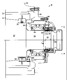
| (54) English Title: | MECHANICAL LOCK FOR ROLLING MILL OIL FILM BEARING |
| (54) French Title: | VERROUILLAGE MECANIQUE POUR PALIER A FILM D'HUILE DE LAMINOIR |
| Status: | Granted and Issued |
| (51) International Patent Classification (IPC): |
|
|---|---|
| (72) Inventors : |
|
| (73) Owners : |
|
| (71) Applicants : |
|
| (74) Agent: | SMART & BIGGAR LP |
| (74) Associate agent: | |
| (45) Issued: | 2011-06-21 |
| (22) Filed Date: | 2008-08-19 |
| (41) Open to Public Inspection: | 2009-03-05 |
| Examination requested: | 2008-08-19 |
| Availability of licence: | N/A |
| Dedicated to the Public: | N/A |
| (25) Language of filing: | English |
| Patent Cooperation Treaty (PCT): | No |
|---|
| (30) Application Priority Data: | |||||||||
|---|---|---|---|---|---|---|---|---|---|
|
An oil film bearing is seated on the tapered neck of a rolling mill roll by a hydraulically actuated piston/cylinder unit. The piston/cylinder unit is axially confined by externally threaded locking arms seated in a groove in the roll neck. A locknut is threaded onto the locking arms.
Un palier à film d'huile est logé sur le tourillon d'un laminoir au moyen d'une unité à piston/cylindre actionnée hydrauliquement. L'unité à piston/cylindre est confinée axialement par des bras de verrouillage à filetage extérieur logés dans une gorge dans le tourillon du laminoir. Un écrou de blocage est fixé par des filets sur les bras de verrouillage.
Note: Claims are shown in the official language in which they were submitted.
Note: Descriptions are shown in the official language in which they were submitted.
2024-08-01:As part of the Next Generation Patents (NGP) transition, the Canadian Patents Database (CPD) now contains a more detailed Event History, which replicates the Event Log of our new back-office solution.
Please note that "Inactive:" events refers to events no longer in use in our new back-office solution.
For a clearer understanding of the status of the application/patent presented on this page, the site Disclaimer , as well as the definitions for Patent , Event History , Maintenance Fee and Payment History should be consulted.
| Description | Date |
|---|---|
| Inactive: COVID 19 - Deadline extended | 2020-08-06 |
| Common Representative Appointed | 2019-10-30 |
| Common Representative Appointed | 2019-10-30 |
| Letter Sent | 2016-10-19 |
| Grant by Issuance | 2011-06-21 |
| Inactive: Cover page published | 2011-06-20 |
| Letter Sent | 2011-04-18 |
| Amendment After Allowance Requirements Determined Compliant | 2011-04-18 |
| Pre-grant | 2011-04-07 |
| Inactive: Amendment after Allowance Fee Processed | 2011-04-07 |
| Amendment After Allowance (AAA) Received | 2011-04-07 |
| Inactive: Final fee received | 2011-04-07 |
| Letter Sent | 2010-12-07 |
| Letter Sent | 2010-12-07 |
| Letter Sent | 2010-10-07 |
| Notice of Allowance is Issued | 2010-10-07 |
| Notice of Allowance is Issued | 2010-10-07 |
| 4 | 2010-10-07 |
| Inactive: Approved for allowance (AFA) | 2010-10-05 |
| Inactive: Office letter | 2010-03-08 |
| Appointment of Agent Requirements Determined Compliant | 2010-03-08 |
| Revocation of Agent Requirements Determined Compliant | 2010-03-08 |
| Inactive: Office letter | 2010-03-08 |
| Revocation of Agent Request | 2010-02-11 |
| Appointment of Agent Request | 2010-02-11 |
| Application Published (Open to Public Inspection) | 2009-03-05 |
| Inactive: Cover page published | 2009-03-04 |
| Inactive: IPC assigned | 2009-02-20 |
| Inactive: IPC assigned | 2009-02-20 |
| Inactive: IPC assigned | 2009-02-20 |
| Inactive: IPC assigned | 2009-02-20 |
| Inactive: IPC assigned | 2009-02-20 |
| Inactive: IPC assigned | 2009-02-20 |
| Inactive: First IPC assigned | 2009-02-20 |
| Inactive: IPC assigned | 2009-02-20 |
| Inactive: IPC assigned | 2009-02-20 |
| Inactive: Filing certificate - RFE (English) | 2008-10-07 |
| Letter Sent | 2008-10-07 |
| Application Received - Regular National | 2008-10-07 |
| Amendment Received - Voluntary Amendment | 2008-08-19 |
| Request for Examination Requirements Determined Compliant | 2008-08-19 |
| All Requirements for Examination Determined Compliant | 2008-08-19 |
There is no abandonment history.
The last payment was received on 2010-07-09
Note : If the full payment has not been received on or before the date indicated, a further fee may be required which may be one of the following
Patent fees are adjusted on the 1st of January every year. The amounts above are the current amounts if received by December 31 of the current year.
Please refer to the CIPO
Patent Fees
web page to see all current fee amounts.
Note: Records showing the ownership history in alphabetical order.
| Current Owners on Record |
|---|
| PRIMETALS TECHNOLOGIES USA LLC |
| Past Owners on Record |
|---|
| ARMANDO S. MARTINS |
| TIMOTHY J. BRADSHAW |

