Note: Descriptions are shown in the official language in which they were submitted.
CA 02639099 2008-08-22
File No:870p1
CANADA
Title: SNOWMOBILE SUSPENSION AND DRIVE TRAIN
Inventor: SHAWN WATLING
1
CA 02639099 2008-08-22
Title: SNOWMOBILE SUSPENSION AND DRIVE TRAIN
Field of the Invention
[001] The present invention claims priority from previously filed provisional
application filed on August 24, 2007 application number 60/957,724 inventor
Shawn Watling
under the title; Snowmobile Suspension and Drive Train. The present invention
relates to a
snowmobile suspension and drive trains.
Background of the Invention
[002] Traditional snowmobile drive trains use a forward drive axle which is
driven by
a j ack shaft which obtains power from the secondary clutch. The present
invention eliminates
the forward drive axle and instead uses a rear drive which includes a chain
and sprocket
drive.
2
CA 02639099 2008-08-22
Summary of the Invention
[003] A snowmobile suspension and drive train for supporting a snowmobile
chassis and
guiding an endless loop type track, the snowmobile suspension and drive train
comprising an
endless loop type snowmobile track supported by a suspension; wherein the
track is being
driven and guided at a rear track position with track rear drive sprockets and
is supported and
guided at a front track position with front idler wheels, wherein an upper
portion of the track
is guided and supported at an intermediate position over top track wheels.
[004] Preferably wherein the front idler wheels positioned within 6 inches
either side
of the balance point.
[005] Preferably wherein the front idler wheels positioned within 2 inches
either side
of the balance point.
[006] Preferably wherein the front idler wheels positioned at the balance
point.
[007] Preferably wherein the suspension includes a upper frame pivotally
connected
3
CA 02639099 2008-08-22
at a pivot point to a horizontally oriented lower frame in scissor
relationship such that the
suspension movable between a raised position and a lowered position.
[008] Preferably wherein in the lowered position the upper frame is oriented
substantially parallel to the lower frame.
[009] Preferably wherein in the raised position the upper frame is oriented
such that it
extends diagonally upwardly relative to the lower frame.
[0010] Preferably wherein in the raised position a reaction force vector
passing
through the pivot point and parallel to the frame rail will intersect with the
center of gravity.
[0011] Preferably wherein in the raised position a reaction force vector
passing
through the pivot point and parallel to the frame rail will pass above the
center of gravity.
4
CA 02639099 2008-08-22
[0012] Preferably 5 wherein the pivot point dividing upper frame into a rear
arm
portion on one side of the pivot point and a front arm portion on the other
side of the pivot
point.
[0013] Preferably wherein in the lowered position rear arm portion raises the
drive
sprockets off of the ground creating a track lifted portion being the part of
the track no longer
contacting the ground thereby creating a track short contact length being the
portion
contacting the ground.
[0014] Preferably wherein in the raised position rear arm portion lowers rear
drive
sprockets toward the ground eliminating a track lifted portion thereby
creating a track long
contact length being the portion contacting the ground.
[0015] Preferably wherein the lower frame including left and right frame
members
having mounted thereon track wheels for supporting the track rollably thereon.
CA 02639099 2008-08-22
[0016] Preferably wherein the pivot point is spaced upwardly from the frame
members
and located in pivot flange projecting upwardly from a rear end of each frame
member
thereby creating L shaped left and right fraine inembers.
[0017] Preferably wherein the suspension is fastened to the chassis with front
adjustable shocks and rear adjustable shocks such that the front track portion
and the rear
track portion can be adjusted up and down independently of each other.
6
CA 02639099 2008-08-22
Brief Description of the Drawings
[0018] The invention will now be described by way of example only with
reference to
the following drawings in which:
Figure 1 is a side schematic partial cut away view of the present invention a
snowmobile
suspension and drive train.
Figure 2 is a top plan view of the snowmobile suspension and drive train.
Figure 3 is a side elevational view of the snowmobile suspension and drive
train.
Figure 4 is a schematic partial assembly view of a portion of the rear shock
assembly and
adjusting mechanism.
Figure 5 is a schematic partial cut away view of the rear shock assembly.
Figure 6 is a top schematic partial cut away view of the snowmobile suspension
and drive
train.
Figure 7 is a partial schematic cut away side plan view of the snowmobile
suspension and
drive train.
Figure 8 is a schematic partial view of components of the chain tensioning
assembly.
Figure 9 is a schematic assembly of a portion of the front shock assembly.
Figure 10 is an assembled partial schematic perspective view of the front
shock assembly
together with the slide rails.
7
CA 02639099 2008-08-22
Figure 11 is a top plan schematic view of the rear shock assembly and the
front shock
assembly shown mounted on the ladder bar frame.
Figure 12 is a partial side schematic view of the rack and rear idle wheels
together with the
rear shock assembly shown in a first position in dark lines and a second
position in light
dashed lines and in a third position an even lighter dashed lines.
Figure 13 is a top schematic plan view of a portion of the snowmobile
suspension and drive
train together with the engine and primary and secondary clutch.
Figure 14 is a schematic partial cut away view of the driven jack shaft
together with various
component mounted thereon including the brake rotor, the front idler wheels,
the front drive
split sprocket and the secondary clutch.
Figure 15 is an exploded assembly view of the mounting hub, the front drive
split sprocket
and the pins and bolts for assembly of the components.
Figure 16 is a rear perspective assembled schematic view of an alternate
embodiment of a
snowmobile suspension and drive train,.
Figure 17 is a top plan view of the snowmobile suspension and drive train
shown in Figure
16.
Figure 18 is a schematic side elevational view of the snowmobile suspension
and drive train
shown in solid lines together with a snowmobile chassis shown in dashed lines.
8
CA 02639099 2008-08-22
Figure 19 is an enlarged side elevational schematic view of the snowmobile
suspension and
drive train shown in Figure 18.
Figure 20 is a schematic side elevational view of the snowmobile suspension
and drive train
deployed in a chassis of a snowmobile shown in dashed lines.
Figure 21 is a side elevational schematic side view of the snowmobile
suspension and drive
train shown in Figure 16 in the raised position.
Figure 22 is a schematic side elevational plan view of the snowmobile
suspension and drive
train in solid lines deployed onto a snowmobile chassis shown in dashed lines.
Figure 23 is an expanded side elevational schematic view of the snowmobile
suspension and
drive train together with front and rear adjustable shocks.
Figure 24 is a side elevational schematic view of the snowmobile suspension
and drive train
shown in Figure 16 together with the drive belt and pulleys together shown
deployed onto a
chassis of a snowmobile.
Figure 25 is a top schematic plan view of the snowmobile suspension and drive
train shown
in Figure 16 using a cog belt drive system to drive the rear drive sprockets
rather than a chain.
Figure 26 is a top schematic plan view of the snowmobile suspension showing
the engine
drive line mounted on the other side of the suspension and drive train
relative to Figures 25
and 17.
9
CA 02639099 2008-08-22
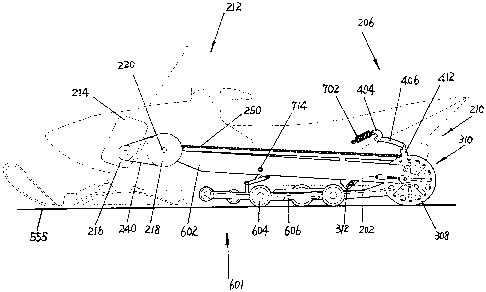
Detailed Description of the Preferred Embodiment
[0019] The attached figures show a snowinobile suspension and drive train
which
includes the following major components, namely ladder bar frame 202, front
shock assembly
204, rear shock assembly 206, drive chain 250, rear drive assembly 210, front
drive assembly
212, engine 214, primary clutch 216 and driven secondary clutch 218.
[0020] Referring now to Figures 13, 14 and 15 front drive assembly 212
includes a live
driven jack shaft 220, a front drive split sprocket 222, a mounting hub 224
and idler wheels
226.
[0021] Front drive split sprocket 222 is mounted onto mounting hub 224 using
pins 230 and bolts 232. Mounting hub 224 is mounted onto driven jack shaft 220
in
traditional manners including splines etc., for rigidly mounting, mounting hub
224 onto
driven shaft 220.
[0022] Driven shaft 220 also includes brake rotor 236 and brake calliper 238
mounted on one end of the driven shaft 220 and the secondary clutch 218
mounted on the
CA 02639099 2008-08-22
other end of driven shaft 220.
[0023] Engine 214 drives primary clutch 216 which in turn drives secondary
clutch 218 via drive belt 240.
[0024] Front drive split sprocket 222 drives drive chain 250.
[0025] Referring now to Figures 2, 3, 4 and 5, rear drive assembly 210
includes fixed
rear axle 302, track sprockets 304, driven chain sprocket 306, rear idler
wheels 308, track
tension assembly 310, rear shock assembly 206 and chain tensioning assembly
312.
[0026] Rear shock assembly 206 includes coil over rear shock 402, upper pivot
arin
404, lower pivot arm 406, rear pivot shaft 408, sprag or splined faces 410 and
connecting link
412.
[0027] Ladder bar frame 202 includes outer rails 602, cross member 608,
stiffening member 610, and has attached thereto idler track wheels 604 and
slide rails 606.
11
CA 02639099 2008-08-22
[0028] Front shock assembly 204 best shown in Figures 9, 10 and 11, includes
an adjustable coil over shock 702, a front pivot ann 704, a slide rail
connecting link 706,
aperture for pivot arm shaft 708, connecting pins 710, connecting link shaft
712 and pivot
arm shaft 714. Front pivot arm 704 also includes shock flanges 720, and shock
mounting
holes 722.
[0029] Chain tension assembly 312 includes the drive chain 250, a slotted
adjustment bracket 802 and a chain idler whee1804.
[0030] Ladder bar frame 202 is connected to the snowmobile chassis at front
ladder bar pivot shaft 692.
[0031] Referring now to Figure 12 showing rear shock assembly 206 together
with the track in various positions by adjusting the rear shock assembly 206
namely by setting
the spline faces 410 relative to each other by clamping upper pivot arm
against rear pivot
shaft 408. In this manner one can align upper pivot arm 404 at relative angles
to lower pivot
arm 406. So for example, one can obtain a track first position 902 by engaging
sprag or
spline faces 410 in such a manner that lower pivot arm takes on first position
912. One can
12
CA 02639099 2008-08-22
obtain track second position 904 by adjusting lower pivot arm into second
position 914 and
one can obtain a track third position 906 as shown in Figure 12. Therefore,
the track 950 can
be adjusted to various heights relative to the chassis of the snowmobile by
adjusting the sprag
or spline faces 410 of the rear pivot shaft 408 relative to the upper pivot
ann 404 with bolt
405. In this manner, one can adjust the ride height to suit individual riding
conditions and
increase or decrease the suspension travel.
Snowmobile Drive Train
In Use
[0032] The presently described rive train includes an engine 214 which drives
a
primary clutch 216 which is connected to a secondary clutch 218 via a drive
belt 240.
Secondary clutch 218 drives a driven jack shaft 220 which is a live shaft
which includes front
drive split sprocket 222 mounted onto a mounting hub 224 connected to driven
jack shaft
220. Driven jack shaft 220 also includes a brake rotor 236 and a brake
calliper 238 mounted
on one distal end thereof. In addition, there are two front idler wheels 226
which guide track
950 over top of and around front drive assembly 212. Front drive split
sprocket 222 drives a
drive chain 250 which in turn is connected to driven chain sprocket 306 which
is mounted on
13
CA 02639099 2008-08-22
fixed rear axle 302.
[0033] Fixed rear axle 302 includes two sets of track sprockets 304 which are
mounted on either side of driven chain sprocket 306. In addition, rear idler
wheels 308 guide
track 950 around rear drive asseinbly 210. Drive chain 250 in addition passes
overtop of two
chain idler wheels 804, the first positioned closer to the front of the
snowmobile and the
second chain idler wheel 804 is part of a chain tensioning assembly 312. Chain
tensioning
assembly 312 includes a slotted adjustment bracket 802 along which chain idler
wheel 804
can be mounted at various positions in order to adjust chain tension. A chain
guard 290 is
also mounted on the upper part of the drive assembly to ensure that chain 250
does not make
contact with any of the parts of the ladder bar frame 202. This drive system
results in
reduced moving components and increased flexibility in that any number of the
sprocket
combinations can be used to determine the final drive ratio and to optimize
the drive train for
any particular driving condition. In addition, rather than the front portion
of the track being
driven, in this case the rear portion of the track is driven, resulting in
completely different
driving characteristics of the snowmobile due to the tensioning on track 950
and the torque
imposed upon the snowmobile during hard acceleration.
14
CA 02639099 2008-08-22
[0034] This drive setup allows for a very stiff ladder bar frame construction
having cross member 608 and stiffening member 610 which pivot about one point
near the
front of the snowmobile namely, about front ladder bar pivot shaft 692.
Snowmobile Suspension
In Use
[0035] The snowinobile suspension includes a front shock assembly 204 and
two rear shock assemblies 206. Front shock assembly 204 includes an adjustable
coil over
shock 702 which is attached at one end to ladder bar frame 202 and at the
other end to shock
mounting hole 722 in front pivot arm 704. In turn, slide rail connecting link
706 is hinge ably
connected to front pivot arm 704 with a connecting pin 710. Slide rail
connecting link 706 is
attached to slide rail 606 which a connecting link shaft 712. Slide rai1606 is
very much the
same as the slide rail assemblies found on existing snowmobiles having a
number of idler
track wheels 604 for guiding the track along the bottom of the snowmobile.
Rear shock
assembly 206 includes rear pivot shaft 408. On each distal end of rear pivot
shaft 408, a coil
over rear shock 402 is mounted to an upper pivot arm 404 which is connected to
rear pivot
shaft 408 with a sprag or spline faces 410 found on both the upper pivot arm
404 and the rear
CA 02639099 2008-08-22
pivot shaft 408. The spline faces are meshed together using a bolt 405 for
rigidly connecting
upper pivot arm 404 to rear pivot shaft 408. In addition, there is a lower
pivot arm 406
rigidly attached to rear pivot shaft 408 which in turn is connected to a
connecting link 412
which is connected at one to the ladder bar frame 202 and at the other end to
lower pivot arm
406. As best shown in Figure 12 via adjusting the position of the sprag or
spline faces 410,
one can select any number of angular positions of lower pivot arm 406 in
relationship to
upper pivot arm 404. Figure 12 shows three such possibilities namely track
first position 902,
track second position 904 and track third position 906. By adjusting the
angular relationship
between the upper pivot arm 404 and the lower pivot arm 406 using the sprag or
spline faces
410, one can have a high riding position and or a low riding position and/or
select large
suspension travel or smaller suspension travel depending upon the position of
the pivot anns.
[0036] The suspension will also include a track tension assembly 310 which is
an assembly well known in the present art. In order to adjust the tension on
track 950, first of
all the chain tensioning assembly 312 would be backed off completely in order
to remove any
tension on drive chain 250. Once drive chain 250 is slack, one can then adjust
the track
tensioning assembly 310 in order to obtain the necessary tension on track 950.
Thereafter,
the chain tensioning assembly 3 12 would be adjusted to obtain the necessary
tension on drive
16
CA 02639099 2008-08-22
chain 250.
Description of Alternate Embodiment of a Snowmobile Suspension and Drive Train
[0037] An alternate embodiment of a snowmobile suspension and drive train is
shown generally as 1000 in Figure 16 and following:
[0038] Snowmobile suspension and drive train 1000 includes the following
major components namely, upper frame 1002 pivotally attached and connected to
lower
frame 1004 at a pivot point 1007 with a pivot shaft 1006. The track 1102 is an
endless loop
type snowmobile track supported by the suspension wherein track 1102 is being
driven and
guided at a rear track position 1404 with track drive sprockets 1036 and is
supported and
guided at a front track position 1402 with front idler wheels 1052 and the
upper portion 1406
of track 1102 is guided at an intermediate position 1408 over top track wheels
1026. Note
that track 1102 is driven at the rear track position 1404 which is where the
track just breaks
contact with ground 1101. With suspension 1000 in raised position 1008 track
1102 breaks
contact with the ground under track drive sprockets. With suspension 1000 in
lowered
position 1010 track 1102 breaks contact with the ground under the rear most
track wheel
17
CA 02639099 2008-08-22
1044. Track 1102 just begins to inake contact with ground 1102 at front track
position 1402
under front idler wheel 1052. Upper portion 1406 of track 1102 does not make
contact with
ground 1101.
[0039] The suspension includes a diagonally extending upper frame 1002
pivotally
connected to a horizontally oriented lower frame 1004 in scissor relationship
pivoting at
pivot point 1007. Upper frame 1002 can be pivoted in scissor like fashion
relative to lower
frame 1004 between a raised position 1008 shown in Figure 21 and a lowered
position 1010
shown in Figure 19. In the lowered position the upper frame 1002 is oriented
substantially
parallel to the lower frame 1004 meaning the frames are within plus or minus
10 degrees
being the angle subtended by the two frames. In the raised position the upper
frame is
oriented such that it extends diagonally upwardly relative to the pivot point
as shown in
figure 21.
[0040] Upper frame 1002 is preferably designed and fabricated in the style of
a ladder
bar 1012 having a right frame rail 1014 and a left frame rail 1016 connected
together with
bars.
18
CA 02639099 2008-08-22
[0041] Upper frame 1002 also includes the following components namely, front
driven shaft 1018 having attached thereon a brake system 1020, a motor driven
pulley 1022
receiving power from the inotor via a motor drive belt 1074. Front driven
shaft 1018 further
includes front sprocket 1024 and top track wheels 1026. Front driven shaft
1018 is located at
the top end 1028 of upper frame 1002 and rear drive shaft 1030 is located at
bottom end 1032
of upper frame 1002. Rear drive shaft 1030 has mounted thereon rear drive
sprocket 1034 for
receiving a chain thereon and track drive sprockets 136 which transmit power
to the
snowmobile track 1102.
[0042] Lower frame 1004 includes a right frame member 1040, a left frame
member
1042, and track wheels 1044.
[0043] Each of the frame members has an idler end 1046 and a rear end 1048.
At idler end 1046, idler shaft 1050 is mounted having front idler wheels 1052
mounted
thereon. Front idler wheels guide the track 1102 around the snowmobile
suspension and
drive train 1000.
[0044] Lower frame 1004 at rear end 1048 includes a pivot flange 1054 which
19
CA 02639099 2008-08-22
as shown in the Figures is an L-shaped flange generally extending
perpendicular to the frame
members 1042 and 1040. Proximate a top end 1056 of pivot flange 1054 is
mounted pivot
shaft 1006 there through thereby pivotally connecting upper frame 1002 to
lower frame 1004
at pivot point 1007.
[0045] Included at the idler end 1046 is a track tensioning mechanism 1060 for
obtaining the necessary track tension onto the track and also for facilitating
removal and
mounting of the track 1102 onto the snowmobile suspension and drive train
components
1000.
[0046] Referring now to Figure 17, the snowmobile suspension and drive train
1000 is shown schematically in a top plan view together with the motor 1070
which drives a
motor drive pulley 1072 which in turn drives a motor drive belt 1074 which in
turn drives the
motor driven pulley 1022 which in turn drives the front driven shaft 1018.
[0047] Brake system 1020 typically includes a brake rotor 1076 and a brake
calliper 1078 of the type known in the art.
CA 02639099 2008-08-22
[0048] Front sprocket 1024 drives a chain 1080 which in turn transmits power
back to the rear sprocket drive 1034 which in turn rotates rear drive shaft
1030 which in turn
rotates drive track sprockets 1036 which transmit turning power to the track
1102 not shown
in this Figure.
[0049] Referring now to Figures 18 and 19 snowmobile suspension and drive
train 1000 in Figure 19 is shown in the lowered position 1010 together with a
track 1102
mounted thereon.
[0050] In the lowered position 1010 shown in Figures 18 and 19, top end 1028
of upper frame 1002 is lowered downwardly to the point where upper frame 1002
lies parallel
and adjacent to lower frame 1004. Tn this position the bottom end 1032 is
raised off of the
ground 1101, thereby reducing the total contact length of the track 1102 as
shown in Figures
18 and 19.
[0051] In particular, shown in Figure 18 is the contact portions of track 1102
when the snowmobile suspension and drive train 1000 is in the lowered position
1010.
21
CA 02639099 2008-08-22
[0052] Track 1102 has a short contact length shown as S 1110 when in the
lowered position 1110 and also has a track lifted portion denoted as C 1112
thereby reducing
the total contact surface of track 1102 onto the ground 1101. The advantages
of having a
short contact length as denoted as 1110 will be discussed below.
[0053] Also will be noted in Figures 18 and 19 that the balance point of the
entire snowmobile with no passengers aboard lies at approximately the position
shown as BP
namely 1114 which is known in the art as the balance point and the centre of
gravity lies at a
point shown as CG 1301. The center of the front idler wheels 1052 are
positioned within 6
inches either side of the balance point, and preferably within 2 inches of
either side of the
balance point, and preferably at the balance point meaning that some portion
of front idler
wheel lies over top of balance point BP 1114 of the sled.
[0054] Additionally shown in Figure 19 is right frame rail 1014 of upper
fraine
1002. Right frame rail 1014 can be subdivided into the rear arm portion shown
as A and
denoted as 1120 and the front arm portion shown as B and denoted as 1122.
Upper frame
1002 pivots about pivot shaft 1006 which subdivides right frame rail 1014 into
the rear arm
portion A1120 and the front arm portion B 1122.
22
CA 02639099 2008-08-22
[0055] The reader will note that when the top end 1028 of right frame rail
1014
is raised thereby raising front arm portion 1122, the bottom end 1032 of right
frame 1014 is
lowered thereby lowering rear arm portion A1120.
[0056] Referring now to Figures 20 and 21, the snowmobile suspension and drive
train
shown generally as 1000 is shown in the raised position 1008. In the raised
position, the total
contact length is long contact length L denoted 1130 in Figure 20 and the
reader will note that
the track lift portion denoted as C 1112 now makes contact with the ground
1101. In the
raised position 1008, the track area contacting the ground is maximized due to
the extended
long contact length L 1130 achieved by lowering bottom end 1032 of upper frame
1002. The
snowmobile chassis 1050 is shown in dashed lines in Figure 18 and 20 for
illustrative
purposes only to show schematically how the snowmobile suspension and drive
train 1000
would be deployed relative to a chassis 1050.
[0057] Referring now to Figures 22 and 23, snowmobile suspension and drive
train 1000 is shown deployed onto a snowmobile chassis 1050 shown in dashed
lines. The
diagram show front adjustable shocks 1200 and rear adjustable shocks 1202
which are
connected to chassis 1050 and are of the type which can be raised and lowered.
Therefore,
23
CA 02639099 2008-08-22
one can select to lower the front adjustable shocks 1200 and/or the rear
adjustable shocks
1202 and/or both thereby adjusting the ride, quality, height and as well
affecting the total
track contact length shown as L 1130 and S 1110 in Figures 18 and 20.
[0058] Figure 25 is a top schematic plan view of the snowmobile suspension
and drive train 1000 similar to the view shown in Figure 17, however in the
case of Figure 25
the chain 1080 is replaced with a cog belt 1220 and a person skilled in the
art will note that
rear sprocket drive 1034 and front sprocket 1024 would be exchanged with front
cog 1222
and rear cog 1224 in order to transmit the drive forces from cog belt 1220 to
the rear cog
1224. In all other respects, the snowmobile suspension and drive train 1000
shown in Figure
25 is similar to the snowmobile suspension and drive train 1000 shown in
Figure 17.
[0059] Referring now to Figure 26, the reader will note that the snowmobile
suspension and drive train shown generally as 1000 may have differently
arranged drive
trains. For example in Figure 26 motor 1070, motor drive pulley 1072, motor
drive belt 1074
and motor driven pulley 1022 are oriented on the left side rather than on the
right side shown
in Figure 17 and 25. It may be possible that the motor position may be found
to be more
convenient and/or efficient in another position than as shown in either Figure
25 or 26 and
24
CA 02639099 2008-08-22
this would still be part of the scope of the spirit of this snowmobile
suspension and drive
train.
[0060] In addition in Figure 26 is shown sponsons 1304 which essentially is a
snow floatation device mounted longitudinally along both sides of frame rails
1014 and 1016.
Sponsons 1304 are used to add floatation in deep snow like a ski and help
prevent the
cliances of getting stuck. The shape and size of the sponsons is optimized for
different
applications such as carving in deep snow, in which case one would want the
sponsons to act
like a ski or rudder. The sponsons may also be constructed larger to form a
shroud in front of
the track radius at the rear track position 1404 to prevent inside radius of
the track from
grabbing or hooking the snow up into the air as the snow enters inside of the
track while
travelling around the rear drive sprocket 1034 or rear idler wheels. This
entrainment of snow
may cause a certain amount of drag in deep snow and the sponsons 1034 can be
shaped to
reduce this drag. The sponson will also add protection to other suspension
components and
absorb impact during possible collision with objects.
[0061] Referring now to Figure 18 and 20, one will note that these figures
also
depict the centre gravity 1301 as shown in the diagrams. The position of the
centre of gravity
CA 02639099 2008-08-22
of the snowmobile relative to the orientation of the ladder bar frame 1012
will create certain
reaction forces when under heavy acceleration and deceleration. It is
preferable that the
ladder bar frames 1012 instance centre is pointing at or above the centre of
gravity 1301 in
order to produce the optimal reaction forces.
Use of Snowmobile and Suspension Drive Train 1000
[0062] Reaction force is applied to ladder bar frame 1012 by means of torque
applied via a chain 1080 and/or a cog belt 1220 to the rear drive sprocket
1034 or rear cog
1224. This creates a reaction force vector along the instant center of the
ladder bar frame
1012. In the raised position for example a force vector runs along an
imaginary line known
as the instant center which passes through the pivot point 1007 and parallel
to the frame rails
1014, 1016. This reaction force vector preferably passes above or intersects
with the center
of gravity 1301 when the suspension is in the raised position 1008. This
reaction force vector
dictates the behaviour of the chassis movement relative to the centre of
gravity 1301. Torque
applied at the rear drive shaft 1030 attempts to extend the suspension while
weight transfer
attempts to compress the suspension. Under operating conditions, the balance
of these forces
is created and the resulting forces increase pressure to the ground while
having minimal
26
CA 02639099 2008-08-22
affect on the front suspension (the pressure on the skis). Force vectoring is
variable by
controlling rear drive shaft 1030 torque and the position of the ladder bar
frames 1012 instant
centre relative to the vehicle centre of gravity 1301. For optimal performance
one would like
to have the ability to position the reaction force vector to pass above or
intersect with the
center of gravity 1301.
[0063] A conventional suspension and drive behaves in an opposite manner
which is a disadvantage. Under heavy acceleration in a conventional
suspension, the front
suspension is unloaded and therefore, the ski pressure on the front skis
decreases, making it
more difficult to control the steering of the snowmobile. While carrying a
passenger, these
disadvantages of the conventional suspension become even more apparent.
[0064] By adjusting the height of rear adjustable shocks 1202 and front
adjustable shocks 1200, one is able to independently adjust the front and/or
rear height of
snowmobile suspension drive train 1000. In Figure 19 for example, the
suspension is shown
in the lowered position 1010, wherein the contact length of the track is at
short contact length
1110. In Figure 21 for example the snowmobile suspension and drive train 1000
is shown in
the raised position 1008, wherein the contact of the track 1102 is the long
contact length L
27
CA 02639099 2008-08-22
shown as 1130. The length of the track 1 l 02 contacting any surface such as
ground 1101 is
variable and can be extended and/or compressed depending upon whether the
suspension is in
the lowered position 1010 and/or the raised position 1008. In deep snow for
example,
increased surface area of the track 1102 is desired and therefore the
suspension is put into the
raised position 1008 which maximizes the contact length L1130 and also raises
the centre of
gravity of the snowmobile. This position is preferably for aggressive riding
in deep snow
and/or over rough terrain.
[0065] By adjusting the suspension to a lower ride height namely, putting in
to lowered
position 1010, one will improve the handling of the snowmobile by decreasing
the surface
area of track 1102 to the short contact length as 1110 and also lowering the
centre of gravity
1301. This perniits tighter turning, reduces lateral weight transfer due to
the lowering of
centre of gravity 1301 and improves turning capabilities and stability of the
snowmobile.
Therefore, suspension right height adjusts track geometry to compliment the
intended purpose
of the riding conditions.
[0066] Snowmobile suspension and drive train 1000 is essentially an endless
loop track 1102 consisting of front idler wheels 1052 placed at the front
track position 1402.
28
CA 02639099 2008-08-22
The idler wheels are located directly below the snowmobile centre of gravity
1301 and at the
balance point 1114 of the snowmobile.
[0067] As indicated above by placing the suspension in lowered position 1110,
one can reduce the track 1102 contact length and by raising the suspension
into the raised
position 1008, one can increase the track contact namely into long contact
length L 1130.
[0068] The mechanical geometry of snowmobile suspension and drive train
1000 provides better performance under deceleration of the snowmobile. The
inability of
conventional snowmobiles to reduce speed and come to a complete stop is well
known.
Several factors are part of this undesirable behaviour. The approach angle of
a traditional
snowmobile at the very first contact point of the track to the snow creates a
rainp effect while
braking. Snow accumulation in front of the track is compressed and forced to
travel below the
track. This causes a hydroplane type action, thereby reducing the ability of
snowmobile to
come to a fast halt.
[0069] Secondly, the track tension in a conventional drive created by the
drive
axle atteinpts to straighten and compress the suspension at the front of the
track under
29
CA 02639099 2008-08-22
deceleration conditions further inducing the ramp effect and further
increasing the
hydroplaning effect.
[0070] Thirdly, the initial contact of the track is almost 14" further back of
the
centre of gravity 1301 as compared to the present snowmobile suspension and
drive train
1000. A lower percentage of the total vehicle weight is applied to the track
and is further
amplified when weight is transferred forward during hard breaking onto the
skis.
[0071] The present snowmobile suspension and drive train 1000, dramatically
improves the ability to reduce speed, increase control and come to a fast
stop. The following
factors make this possible. The front idler wheels 1052 found in the forward
portion of the
track are almost directly under the vehicles centre of gravity 1301 and
directly under the snow
machines balance point 1114. The centre of gravity point 1301 of course
changes depending
upon the number of passengers that are riding on the snowmobile, but generally
speaking, the
centre of gravity 1301 will move further back as additional passengers are
added to the
vehicle. This movement on the centre of gravity position 1301 backward with
the additional
passengers, aids braking since a high percentage of the vehicles weight is
applied to the front
idler wheel 1052 under high breaking.
CA 02639099 2008-08-22
[0072] A third factor to increase traction under heavy breaking involves a
direction of the forces applied to the front idler wheel 1052. The top track
wheel 1026
applies force forwardly through the right and left frame members 1040 and
1042. Thereby
transferring the energy and pivoting the ladder bar frame 1012. This effect
causes further
force to be applied to front idler wheel 1052 thereby reducing or preventing
hydroplaning and
causing idler wheel 1052 to dig in or assert more pressure onto ground 1101.
The front skis
therefore remain f rmly planted in the snow therefore maintaining steering
control of vehicle
and deceleration is greatly improved.
[0073] In addition, the distance between the motor drive pulley 1072 and the
motor driven pulley 1022 is increased. This provides greater efficiency of the
variable speed
transmission since the area of contact around the primary clutch 1.021 is
increased, therefore
reducing belt slippage, lowering heat created, increases belt life, increases
reliability and
effectively transfers power more efficiently to front driven shaft 1018.
Manufacturing costs
and assembly time are also reduced, due to less critical specifications for
drive belt alignment
due to the long drive centre between the motor drive pulley 1072 and the motor
driven pulley
1022. In addition, the chain case which is typically a part of the present day
snowmobile
31
CA 02639099 2008-08-22
drive trains is completely eliminated and therefore, less distance is required
to transmit power
to the ground.
[0074] The track tension is applied to approximately 40% of the track to
transmit power to only the portion that contacts the ground, as the top side
of the track
essentially free wheels. This is because the rear drive shaft 1030 is the
driven axle of the
drive train. By applying the rotating or the torque to the rear portion of the
track, one is
essentially pulling track 1102 around front idler wheel 1052 and backwards
around rear drive
sprocket 1034, therefore applying tension along the bottom portion of track
1102 which is
more or less in contact with the ground 1101. This reduces track fatigue and
proves rolling
resistance around the large diameter front idler wheel 1052. The track can be
operated quite
loose with very little tension and without track skipping or ratcheting
whether breaking or
accelerating.
[0075] A convention sled applies tension to 90% of the track in order to
transmit power to the ground. A conventional sled a large portion of the track
is part of the
transmission and in particular the top side of the track transmits power to
the ground.
32
CA 02639099 2008-08-22
[0076] The reader will note that the front and rear track suspension can
travel
independently. In other words, front adjustable shock 1200 and rear adjustable
shock 1202
can be independently raised and lowered and not coupled together as in a
conventional
suspension system. The present suspension can isolate the tuning, front or
back and give
considerable increase in rider comfort and control. In conventional
suspensions, by adjusting
either the front or back, it automatically affects other parts of the
suspension.
[0077] The present invention applies chassis load through the through the
ladder
bar frame 1012 to the rear drive shaft 1030. Therefore, when a passenger is
present on a
snowmobile, they are sitting well ahead of the rear drive shaft 1030. The
passenger's weight
does proportionally add weight to the front skis which is need to maintain
control of the
snowmobile.
[0078] This is not the case in conventional snowmobiles, wherein the front
skis
are unloaded with the presence of passengers onto the back of the snowmobile.
[0079] The present design is very versatile in that the user has the
capability to
adjust ride height while stationary or under motion. It is possible to have
the entire weight of
33
CA 02639099 2008-08-22
the vehicle placed on the front idler wheels 1052 which allows the operator to
easily pivot the
snowmobile around balancing only on the front idler wheel 1052. A 500 pound
sled under
these conditions requires only 20 pounds of pull at a rear grab handle located
near the rear
drive sprocket 1034 in order to turn the sled totally around on dry pavement,
or hard packed
snow by positioning the entire weight of the snowmobile over front idler wheel
1052. Small
children and the elderly with back trouble and people who are unable to bend
and push and/or
pull to a great degree can easily completely pivot the snowmobile around the
front idler
wheels 1052 by silnply positioning the suspension in such a manner that the
majority of
weight is concentrated over the front idler wheel 1052.
[0080] The same capability while riding the vehicle, allows the operator to
raise
the skis off the ground to cross the road or surface that may cause damage to
the front ski
carbide runners and also to public property.
[0081] The same capability also gives the operator the choice to adjust the
ski
pressure downwards while operating the snowmobile. This is desirable for
different
operating conditions which change the handling characteristics and the bands
of the
snowmobile. For instance if you are cariying a heavy load or a passenger, you
may choose to
34
CA 02639099 2008-08-22
raise the rear end in order to level out the vehicle. In deep snow you may
choose to have
little or no ski pressure to make the snowmobile nibble and easy to carve by
only shifting
your weight.
[0082] In addition to this the present design reduces manufacturing costs,
assembly time, it simplifies and reduces the number of parts. The method used
to
manufacture may be less costly and in particular maintenance procedures may
also be less
time consuming.
[0083] It should be apparent to persons skilled in the arts that various
modifications and adaptation of this structure described above are possible
without departure
from the spirit of the invention the scope of which defined in the appended
claim.