Note: Descriptions are shown in the official language in which they were submitted.
CA 02639263 2008-09-04
DATA TRANSMISSION SYSTEM
Field of the Invention
This invention relates to wireless data transmission system and is
particularly, but not
exclusively, applicable to land seismic surveying systems.
Background to the Invention
In land seismic surveys, an array of geophones is used to detect reflections
from
subsurface earth formations of acoustic signals which are generated at, or
near to, the surface
of the earth. Geophysicists planning seismic surveys determine the positions
where
geophones are to be placed during a survey, normally on the earth's surface
but commonly
also in boreholes. These positions are known as stations, and one or more
interconnected
geophones may be placed at these stations. Such a collection of interconnected
geophones is
referred to as a geophone group, even if it consists of a single geophone.
The output of a geophone group is an analogue signal which is required to be
digitized by a high-precision 24-bit analogue-to-digital converter to
facilitate the high
fidelity recording of the signal. As the geophone groups are typically
distributed over a wide
geographical area, it has become a common technique to deploy digitizer units
containing
between one and eight analogue-to-digital converters across the survey area,
and to
interconnect these digitizing units using cable to create a data transport
network to transfer
the digitized geophone signals to the data recorder.
Wireless systems have also come into use, as has the use of optical fibre
cable to
handle high data transfer rates. These developments, together with improved
data
processing, have allowed the use of larger seismic spreads and higher
resolutions.
In our US 6219620 (= EP 0934538) there is described a seismic acquisition
system in
which the terrain is divided into cells, and digitizer units within each cell
communicate with
a cell controller by wireless techniques. The cell controllers then
communicate with a
central control unit by wireless or fibre optic cable. Such an arrangement
greatly reduces the
amount of work required to set up the seismic spread, and also allows a large
amount of data
to be processed virtually in real time.
I
CA 02639263 2008-09-04
SUMMARY OF THE INVENTION
The present invention seeks to further enhance the deployment efficiency of
the
system by means of a self-configuring and self-adapting wireless data
networking system.
The invention provides a data transmission system for transmitting digital
data
between a multiplicity of remote stations and a central control unit. At the
central control
unit, the interface to the data transmission system is via one or more root
nodes. Each of the
remote stations comprises a first transceiver, a second transceiver and a
control means; the
first transceiver being operable as a wireless client, capable of
communicating with an access
point; and the second transceiver being operable as an access point to which
the wireless
client transceivers of other remote stations may connect. The controller
within the remote
station provides a means of routing data between the two transceivers.
From another aspect the invention provides a seismic survey system comprising
a
data transmission system in accordance with the preceding paragraph and in
which each of
the remote stations is a remote acquisition unit connected to one or more
geophones to form
a geophone group.
A further aspect of the invention provides a remote acquisition unit for use
in seismic
surveying comprising a remote station as defined above, input means for
connection to one
or more geophones, and means for storing and forwarding seismic data received
from said
geophone(s).
Preferred features and advantages of the invention will be apparent from the
claims
and from the following description.
BRIEF DESCRIPTION OF THE DRAWINGS
An embodiment of the invention will now be described, by way of example only,
with reference to the drawings, in which:
Fig. 1 is a schematic overview of a seismic surveying system;
Fig. 2 is a block diagram illustrating one remote acquisition unit in the
system of Fig. 1;
2
CA 02639263 2008-09-04
Fig. 3 is a flow chart of a process performed by the remote acquisition unit
in
establishing a communication route.
Fig. 4 is a block diagram illustrating part of an example of a network
embodying one aspect of the invention.
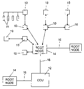
Referring to Fig. 1, a seismic survey system comprises a number of remote
acquisition units (RAUs) 10 distributed across a survey terrain. Each RAU 10
is connected
to one or more geophones 11 forming a geophone group. It will be appreciated
that Fig. 1 is
schematic and that in practice several thousand RAUs may be used.
Seismic data from the geophones is ultimately transferred to a central control
unit
(CCU) 12. In the present embodiment, data is transferred from each RAU 10 by a
wireless
system to be described to a root node 14, and the root nodes 14 communicate
with the CCU
12. Each root node 14 takes the form of one or more wireless access points
which are
connected to the CCU 12 by a high speed data network 16 which will typically
be fast
Ethernet or Gigabit Ethernet which may use copper, fibre optic or wireless as
transmission
medium.
Turning to Fig. 2, each RAU 10 has an input 20 for receiving geophone signals,
an
analog-to-digital converter 22 (not required if the geophone signals are
digital), and a
memory 24 for temporarily storing the digital signals. The RAU 10 also
comprises two
radio transceivers, namely a first transceiver 26 referred to herein as an
"upstream"
transceiver, and a second transceiver 28 referred to herein as a "downstream"
transceiver,
and a control circuit 27.
The upstream transceiver 26 operates as a wireless client while the downstream
transceiver 28 operates as an access point, as will be described. Each of the
root nodes 14
includes a wireless transceiver operating as an access point.
Each of the downstream wireless transceivers 28 and root node 14 wireless
transceivers operating as an access point may be configured to broadcast a
beacon signal.
This beacon signal contains a parameter indicating the logical distance of the
node from the
CCU. The root node 14 wireless transceiver shall have this parameter set to 0.
3
CA 02639263 2008-09-04
When a seismic array is deployed, as in Fig. 1, on being powered up, a RAU 10
enables its upstream transceiver 26 and seeks to establish communication with
a root node
14 by searching for a beacon signal with a logical distance parameter of 0. On
detecting the
beacon, the transceiver associates with the root node and is enabled as a
wireless client of the
network. The downstream transceiver 28 of the same RAU 10 is enabled as an
access point
using a different wireless frequency, and broadcasts a beacon with the logical
distance
parameter set to 1, identifying the RAU as a relay node.
If the upstream transceiver 26 cannot establish communications with a root
node 14,
it then searches for a beacon signal broadcast by a relay node. If multiple
beacons are
detected, the upstream transceiver 26 will preferentially connect to an access
point
broadcasting a beacon containing the lowest logical distance. If the lowest
logical distance is
detected from multiple beacons, preference is give to the one which is
evaluated to have the
best communications path based on a set of metrics, including, but not limited
to, received
signal strength, packet error rate and link data rate. On detecting an
appropriate beacon, the
transceiver associates with the access point transmitting the beacon and is
enabled as a
wireless client of the network. The downstream transceiver 28 of the same RAU
10 is then
enabled as an access point using a different wireless frequency, and
broadcasts a beacon with
the logical distance parameter set to a value of 1 greater than that contained
in the beacon
detected by the upstream transceiver 26.
It will be appreciated that as the system is brought into use, the RAUs will
adaptively
form a network with optimum efficiency. It is preferred that the evaluation
carried out by the
RAUs is repeated at intervals during use of the system to take account of
changes in signal
propagation and environmental factors.
Fig. 3 illustrates in flow chart form the process of evaluating and
association carried
out within an RAU.
Fig. 4 shows a very small part of the network to illustrate connections which
may be
made. RAU l0A is able to communicate directly with root node 14. RAU l OB
cannot
conununicate directly with root node 14, and establishes communication via RAU
I OA.
RAU lOC communicates via lOA and 10B. RAU I OD can communicate with either of
lOB
4
CA 02639263 2008-09-04
and lOC and will select the route which is most efficient on the basis of the
metrics received.
This would most likely be via l OB as requiring the fewest hops, but could be
via l OC if the
channel from l OD directly to l OB is of poor quality.
In the network formed in this way the operation of each RAU is analogous to
that of
an Ethernet switch on a copper Ethernet network. Each RAU has an associated IP
address
and the central control unit 12 maintains a routing table. Once the network
has been
established, the routing table is relatively static.
The system is similar in topography to a wireless mesh network, but is
significantly
different in operation. In a conventional wireless mesh network there is a
single
transmitter/receiver in each unit. While one unit is transmitting other units
on the same route
are limited to receiving. The effect is that as the mesh grows there is
increasing latency and
the effective bandwidth is greatly reduced. In the present system, by using
two transceivers
per unit there is a small degree of latency and effectively zero (or very
small) reduction in
bandwidth as the system grows.
US 2005/0143133 A1 describes a wireless communication system based on nodes.
Each node contains two transceivers. This might appear at first sight to be
similar to the
present invention. However, in this prior art documents the two transceivers
are provided for
specific purposes, namely one for handling wireless communication between
nodes and the
other acting as a wireless LAN station for working with wireless devices
outside the
communication mesh, and thus would suffer as discussed above from increasing
latency as
the mesh grows. US 2005/0143133 Al does not suggest one transceiver acting as
a wireless
client communicating with an access point and the other acting as an access
point for other
similar devices. The arrangement of the present invention effectively provides
full duplex
communication between RAUs or nodes.
Although described with particular reference to land seismic surveying, the
invention
is equally applicable to other uses where large quantities of data must be
collated from a
large number of dispersed locations.
5