Note: Descriptions are shown in the official language in which they were submitted.
CA 02639418 2008-09-08
,
56.1117
PUMP ASSEMBLY
BACKGROUND
100011 A variety of systems and methods are used for pumping
fluids in many
well related applications. In well treatment operations, for example, one or
more surface
pumps are used to pump the treatment fluids, such as fracturing fluids,
cementing fluids,
gravel packing slurries, and other fluids to a desired formation or other
subterranean
region. In many of these applications, substantial amounts of fluid are
directed downhole
under pressure to perform the desired well related treatment.
100021 During the pumping operation, more than one pump may be
employed to
obtain the desired flow, pressure, and/or redundancy. In applications where
more than
one pump is utilized, more than one engine must be employed to drive the pumps
or the
output of a single-engine must be run through a splitter box which splits the
engine
output to a plurality of splitter box output shafts. In one prior arrangement,
a single
engine is coupled to a splitter box which, in turn, drives two transmissions.
Each
transmission is coupled to and drives a corresponding pump. In another prior
arrangement, a single-engine is connected to a transmission which, in turn, is
coupled to a
splitter box. The separate output shafts of the splitter box are coupled to
and drive
corresponding pumps. However, such prior systems are costly because of the
required
number of expensive components, including a splitter box and/or multiple
transmissions
and multiple engines.
SUMMARY
100031 In general, the present invention provides a system and
method for
pumping fluids in a well related application while minimizing the number of
system
components. The system and methodology comprise a plurality of pumps for use
at a
well site to deliver a well treatment fluid to a desired location. A single
driveline is
1
CA 02639418 2008-09-08
,
56.1117
,
,
coupled between a motive unit and the plurality of pumps without incorporating
a splitter
box. The driveline is driven by the motive unit to rotate the plurality of
pumps.
[00041 A system for pumping comprises a mobile platform, a a
motive unit
mounted on the mobile platform, a plurality of pumps mounted on the mobile
platform,
and a drive shaft forming a driveline driven by the motive unit, the drive
shaft being
coupled with a solid, direct connection to the plurality of pumps without
splitting the
driveline. The motive unit may comprise one of an internal combustion engine,
a gas
turbine, an electric motor, and a hydraulic motor. Alternatively, the system
further
comprises a transmission coupled to the internal combustion engine and to the
drive
shaft. Alternatively, the plurality of pumps comprises two pumps.
[0005] Alternatively, the plurality of pumps comprises more
than two pumps.
Alternatively, each pump of the plurality of pumps comprises a positive
displacement
pump. Alternatively, the drive shaft extends through a first pump to a second
pump.
Alternatively, the drive shaft comprises an external drive shaft being
directly coupled to
each pump of the plurality of pumps by a gear. Alternatively, the system
further
comprises a pump release system to enable selective release of an individual
pump from a
pumping operation. Alternatively, the mobile platform is one of a truck
trailer, a skid,
and a self-propelled platform.
[0006] In an embodiment, a method of delivering a well
treatment fluid comprises
providing a plurality of pumps at a well site, coupling a single driveline
directly to the
plurality of pumps without a splitter box, engaging the driveline with the
motive unit for
rotating the driveline and powering the plurality of pumps, and delivering a
well
treatment fluid downhole to perform at least one well treatment operation.
Alternatively,
delivering comprises delivering one of a fracturing treatment fluid, a
cementing treatment
fluid, and a coiled tubing service fluid. Alternatively, providing comprises
providing a
plurality of positive displacement pumps. Alternatively, coupling comprises
coupling a
drive shaft with a solid, direct connection to the plurality of pumps so that
the drive shaft
extends through at least one pump. Alternatively, coupling comprises coupling
a drive
2
CA 02639418 2008-09-08
56.1117
shaft with a solid, direct connection to the plurality of pumps so that the
drive shaft is
disposed externally of the plurality of pumps.
[0007] Alternatively, engaging comprises connecting the driveline to one
of an
internal combustion engine, a gas turbine, an electric motor, and a hydraulic
motor.
Alternatively, the method further comprises using a pump release system in
cooperation
with the plurality of pumps to enable selective release of an individual pump
from a
pumping operation via a mechanical disconnect of the individual pump.
Alternatively,
the method further comprises using a pump release system in cooperation with
the
plurality of pumps to enable selective release of an individual pump from a
pumping
operation via a hydraulic rerouting system. Alternatively, the method further
comprising
mounting the plurality of pumps and the motive unit on a mobile platform.
[0008] In an embodiment, a system comprises a plurality of pumps mounted
at a
surface location for use in delivering treatment fluid downhole in a well
treatment
operation, a motive unit, a single shaft coupling the motive unit to the
plurality of pumps
without splitting the single shaft, and a pump release system selectively
operable to
release individual pumps from delivering treatment fluid downhole.
Alternatively, the
pump release system comprises a mechanical release system. Alternatively, the
pump
release system comprises a hydraulic rerouting system. Alternatively, the
system further
comprises at least one mobile platform, wherein the plurality of pumps and the
motive
unit are mounted on the mobile platform.
[0009] Alternatively, the system further comprises at least two mobile
platforms,
wherein the plurality of pumps are mounted on a mobile platform and the motive
unit is
mounted on a separate mobile platform. Alternatively, the single shaft is
coupled to the
plurality of pumps via pinion gears. Alternatively, the single shaft is
coupled to the
plurality of pumps via a transfer case. Alternatively, the pump release system
comprises
a plurality of valves to selectively stop flow of the treatment fluid to or
from the pumps.
Alternatively, the pump release system is connectable such that an angle of
rotation
between the pumps is selectable.
3
CA 02639418 2013-09-05
54138-85
[0009a] Another embodiment relates to a system for pumping,
comprising: a mobile
platform; a motive unit mounted on the mobile platform; a plurality of pumps
mounted on the
mobile platform; a drive shaft forming a driveline driven by the motive unit,
the drive shaft
being coupled with a solid, direct connection to the plurality of pumps
without splitting the
driveline; and a pump release system in cooperation with the plurality of
pumps to enable
selective release of at least one of the plurality of pumps from delivering
well treatment fluid
downhole to perform at least one well treatment operation.
[0009b] A further embodiment relates to a method of delivering a well
treatment fluid,
comprising: providing a plurality of pumps at a well site; coupling a single
driveline directly
to the plurality of pumps in series without a splitter box; engaging the
driveline with a motive
unit for rotating the driveline and powering the plurality of pumps; and using
a pump release
system in cooperation with the plurality of pumps to enable selective release
of at least one of
the plurality of pumps from delivering well treatment fluid downhole to
perform at least one
well treatment operation.
[0009c] A still further embodiment relates to a system, comprising: a
plurality of
pumps mounted at a surface location for use in delivering treatment fluid
downhole in a well
treatment operation; a motive unit; a single shaft coupling the motive unit to
the plurality of
pumps without splitting the single shaft; and a pump release system in
cooperation with the
plurality of pumps to enable selective release of at least one of the
plurality of pumps from
delivering well treatment fluid downhole to perform at least one well
treatment operation.
3a
CA 02639418 2008-09-08
56.1117
BRIEF DESCRIPTION OF THE DRAWINGS
[0010] Certain embodiments of the invention will hereafter be described
with
reference to the accompanying drawings, wherein like reference numerals denote
like
elements, and:
[0011] Figure 1 is an illustration of an embodiment of a truck trailer
mounted
pumping system;
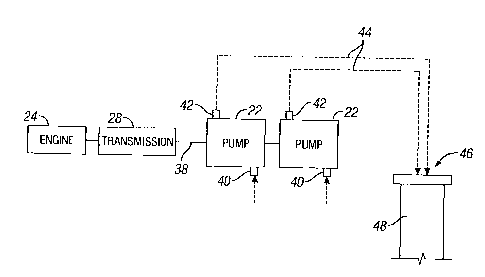
[0012] Figure 2 is a schematic illustration of one example of an
embodiment of a
pumping system for delivering treatment fluid;
[0013] Figure 3 is a schematic illustration of another example of an
embodiment
of a pumping system for delivering treatment fluid;
[0014] Figure 4 is a schematic illustration of another example of an
embodiment
of a pumping system for delivering treatment fluid;
[0015] Figure 5 is a schematic illustration of another example of an
embodiment
of a pumping system for delivering treatment fluid; and
[0016] Figure 6 is a schematic illustration of another example of an
embodiment
of a pumping system for delivering treatment fluid.
DETAILED DESCRIPTION
[0017] In the following description, numerous details are set forth to
provide an
understanding of embodiments of the present invention. However, it will be
understood
by those of ordinary skill in the art that the present invention may be
practiced without
4
CA 02639418 2008-09-08
= 56.1117
these details and that numerous variations or modifications from the described
embodiments may be possible.
[0018] Embodiments of the present invention generally relates to a
system and
method for pumping fluid in a variety of well related applications. The system
and
methodology may utilize pumps positioned at a surface location to pump
selected
treatment fluids downhole. For example, the pumping system can be used to pump
fracturing fluids, cementing fluids, and other well treatment fluids downhole
for
performance of a given well related operation.
[0019] The design of the pumping system eliminates the need for
expensive
components, such as a splitter box, additional transmissions, and additional
engines.
Furthermore, the system and methodology provide for smoother torque variations
on the
transmission used in the pumping system. In some embodiments, the position of
the
cranks between pumps is movable during assembly and fixed once assembled for a
pumping application. The pumping system also enables at least partial
redundancy. In
these applications, selected pumps can be released from the pumping operation
by, for
example, disconnection from the driveline or by separating the output flow
from the
discharge piping. The pumping system design enables the number of pumps to be
increased without adding substantial complexity.
[0020] Referring generally to Figure 1, one example of an
embodiment of a
pumping system 20 is illustrated. In this example, the pumping system 20 is a
transportable system that may be transported over the highway system to a
given job site.
As illustrated, pumping system 20 is a truck trailer mounted system having a
plurality of
pumps 22. The pumping system 20 may comprise two pumps 22 or more than two
pumps 22 depending on the requirements of a given well related operation. For
example,
additional pumps 22 can be added to meet increased flow volume, pressure,
redundancy
and other requirements for a well treatment operation or other well related
operation.
CA 02639418 2008-09-08
56.1117
[0021] As illustrated in Figure 1, pumping system 20 further comprises a
motive
unit 24 coupled to pumps 22 via a driveline 26. The motive unit 24 may provide
power
to rotate driveline 26 and thus pumps 22 through a transmission 28. Driveline
26 may
comprise a drive shaft that is coupled to the plurality of pumps 22 via a
solid, direct
connection without splitting the driveline. The solid, direct connection of
driveline 26 to
pumps 22 enables the transfer of substantial power from motive unit 24 to the
pumps 22.
In the embodiment illustrated, motive unit 24 comprises an internal combustion
engine
connected directly to transmission 28. Alternatively, motive unit 24 is a
turbine, an
electric motor, a hydraulic motor, or similar apparatus suitable for driving
the pumps 22.
100221 In the embodiment of Figure 1, the plurality of pumps 22 and
motive unit
24 are mounted on a mobile platform 30 such as, but not limited to, a truck
trailer 30. By
way of example, truck trailer 30 may comprise a flatbed trailer designed for
movement
from one well location to another by a suitable tractor 32. Additional
components, such
as fuel tanks 34 or storage tanks 36, also can be mounted on truck trailer 30.
The overall
pumping system 20 comprises a simple, movable pumping system having a single
engine,
or other motive unit, and a single transmission to drive the plurality of
pumps.
Alternatively, pumping system 20 is a self-propelled system mounted on, for
example, a
truck or similar self-propelled vehicle, as will be appreciated by those
skilled in the art.
Alternatively, the mobile platform 30 is a skid or similar structure suitable
for being
transported via land vehicles (such as a removable mount to a truck trailer),
waterborne
vessels (such as a removable mount to a ship, barge, or the like), or air
vehicles (such as a
removable mount to an airplane or helicopter or suitable for lifting by a
helicopter), as
will be appreciated by those skilled in the art.
100231 The motive unit 24, transmission 28 and pumps 22 may be directly
connected in several configurations. As illustrated in Figure 2, for example,
the motive
unit 24 comprises an engine directly connected to transmission 28 which, in
turn, is
directly connected to the plurality of pumps 22 by a drive shaft 38. In this
embodiment,
the motive unit 24 comprises an engine driving at least two pumps 22 without
splitting
the driveline via, for example, a splitter box. The multiple pumps 22 are
driven by the
6
CA 02639418 2008-09-08
56.1117
same drive shaft 38, and the drive shaft 38 extends through at least some of
the pumps 22
and/or one or more components of the pumps 22. For example, the drive shaft 38
may
extend through at least the first pump 22 to the second pump 22 to drive both
and/or each
of the pumps.
[0024] In other configurations, pumping system 20 comprises more than two
pumps 22 with the drive shaft extending directly through two or more pumps to
the final
pump. By way of example, a single drive shaft passing through the pumps and/or
one or
more components of the pumps 22 may be used. In an alternate example, the
input shaft
of each pump is sequentially connected to the input shaft of the next pump,
e.g. the
crankshafts of the plurality of pumps are linked. Regardless, the drive shaft
38 forms a
solid, direct connection with each pump 22 by mechanically engaging each pump.
The
direct, mechanical connection facilitates the transfer of power from the
motive unit 24
even under high load pumping conditions. The drive shaft 38 preferably
maintains a
fixed relationship between the angle of rotation of the shafts of the pumps 22
such that
the pumps 22 are rotated in a synchronous manner.
[0025] Pumps 22 may comprise a variety of pump types, however positive
displacement pumps are useful in many pumping applications. Examples of such
pumps
include duplex pumps, triplex pumps, quintuplex pumps, sixtuplex pumps and
septuplex
pumps. The positive displacement pumps are useful in a variety of well
treatment
operations including, but not limited to, fracturing operations and cementing
operations.
When conducting a treatment operation, motive unit 24 rotates drive shaft 38
to drive
pumps 22 which, in turn, draw treatment fluid into the pumps 22 through
corresponding
inlets 40. The treatment fluid is pumped and discharged through corresponding
pump
outlets 42. From outlets 42, the treatment fluid is directed along an
appropriate flow path
44 including, but not limited to, a path via jointed tubing, coiled tubing or
the like, to a
well 46 to be treated. For example, the treatment fluid may be directed
downhole into a
wellbore 48 to a desired well treatment region that is to be fractured,
cemented or
otherwise treated, such as with gravel packing slurries, coiled tubing service
fluids and/or
other fluids, as will be appreciated by those skilled in the art.
7
CA 02639418 2008-09-08
56.1117
[0026] Another embodiment of pumping system 20 is illustrated in Figure 3.
In
this embodiment, pumps 22 are again arranged in series and the solid, direct
connection
between drive shaft 38 and pumps 22 is achieved with the drive shaft 38
located in a
position external to the two or more pumps 22. The solid, direct connection
between
drive shaft 28 and pumps 22 may be formed with a gear system 50. For example,
a gear,
such as a pinion gear 52, may be connected between drive shaft 38 and each
pump 22.
The gear 52 can be mounted on or engaged with drive shaft 38 to directly drive
an input
shaft of each pump or to directly drive gears engaging the input shaft of each
pump 22.
[0027] The pumping system 20 also may be designed with a pump release
system
54, as illustrated in Figure 4. The pump release system 54 is designed to
enable selective
release of individual pumps from a pumping operation. For example, individual
pumps
22 can be released from participation in a given well treatment operation
when, for
example, pumping requirements change, equipment malfunctions occur, a
redundant
system is desired, or other factors arise requiring release or removal of one
or more
pumps 22 from the well operation.
[0028] In the embodiment illustrated in Figure 4, pump relief system 54
comprises a mechanical release 56 associated with each pump 22. Each
mechanical
release 56 may be manually controlled or controlled by an actuator, such as a
solenoid, a
hydraulic actuator, or other suitable actuator. Actuation of a selected
mechanical release
56 disconnects the corresponding pump 22 from shaft 38 to enable continued
rotation of
shaft 38 without operation of the corresponding pump 22. The mechanical
release 56
may comprise a variety of coupling members that couple drive shaft 38 to the
pumps 22.
For example, the mechanical release may comprise a pin, a key, a hydraulic
lock, or other
features that enable decoupling of shaft 38 from a specific pump 22, such as,
but not
limited to, a clutch or the like. The mechanical release 56 can be located
externally or
internally with respect to each pump 22 depending on whether shaft 38 extends
through
the interior of pumps 22 or along the exterior. In external shaft embodiments,
for
8
CA 02639418 2008-09-08
56.1117
example, the mechanical release 56 may comprise a coupling member located to
couple
the pinion gear 52 with its corresponding pump 22.
[0029] An embodiment of pump release system 54 is illustrated in Figure 5.
In
this embodiment, the pump release system 54 does not comprise a mechanical
disconnect
but rather features a hydraulic rerouting system 58 which is used to redirect
fluid
discharged through the outlet 42 of a specific pump 22. According to one
example, the
hydraulic rerouting system 58 enables the discharge pressure of a select pump
or pumps
to be injected into the suction side of the pumping system 20 to prevent
participation of
the selected pump or pumps 22 in the specific well treatment operation.
[0030] In the embodiment illustrated, the hydraulic rerouting system 58
comprises a check valve 60 disposed in the outlet 42 of each pump 22. The
check valves
60 allow one-way flow of fluid to flow path 44 which may be along a discharge
line 62
that ultimately directs the discharged fluid downstream, such as to the
wellbore 48 shown
in Fig. 2. Each check valve 60 blocks back-flow of fluid from discharge line
62 to the
corresponding pump 22. The hydraulic rerouting system 58 further comprises a
fluid
rerouting line 64 for each pump 22. Each fluid rerouting line 64 is connected
to one of
the outlets 42 between the check valve 60 and its corresponding pump 22 to
enable
rerouting of fluid flow discharged from the corresponding pump 22 to a suction
line or
intake line 66. The suction line 66 is connected to the intake or inlets 40 of
all of the
pumps 22.
[0031] A valve 68 is disposed along each fluid rerouting line 64 and may
be
controlled by an appropriate actuator 70. For example, each valve 68 may be
selectively
moved between a flow position (see valve on right side of Figure 5) and a no-
flow
position (see valve on left side of Figure 5). As illustrated by the valve 68
on the right
side of Figure 5, positioning the valve 68 in an open or flow position enables
fluid
discharged from the corresponding pump 22 to be rerouted through fluid
rerouting line 64
and into suction line 66. If, however, valve 68 is closed as illustrated on
the left side of
Figure 5, fluid is forced through the corresponding check valve 60 and into
discharge line
9
CA 02639418 2008-09-08
56.1117
62. The check valves 60 further prevent the cross flow of fluid from one pump
to the
discharge side of another pump.
100321 Alternatively, one or the other of the pumps 22 may be unloaded
and/or
shut down by removing the suction supply, such as by shutting a suction valve
72
disposed in the inlet 40 of the pump 22. Alternatively, a pump 22 may be
unloaded
and/or shut down by closing a discharge valve 74 disposed in the outlet 42 of
the pump
22. Alternatively, a pump 22 may be unloaded and/or shut down by opening the
pump 22
to atmosphere closing the suction valve 72 and discharge valve 74 and opening
a vent
valve 76 disposed in the inlet 40 and/or a vent valve 78 disposed in the
outlet 42 of the
pump 22.
100331 Another embodiment of pumping system 20 is illustrated in Figure 6.
In
this embodiment, pumps 22 are again arranged in series and the solid, direct
connection
between drive shaft 38 and pumps 22 is achieved with the drive shaft 38
connected to a
two output shaft transfer case or drop box 80, wherein the drive shaft 38 is
in direct
connection a gear (not shown) in the transfer case 80, and the gear in the
transfer case 80
is directly connected with a drive shaft 82 drives either or both of the pumps
22. The
gears in the transfer case 80 are preferably substantially similar in size to
enable the drive
shaft 82 to drive the pumps 22 as if the pumps 22 were directly connected to
the drive
shaft 38. The pumps 22 may be connected and disconnected from the shaft 82,
such as
with the pump disconnect system 54 shown in Fig. 4, with a clutch, or similar
device, as
will be appreciated by those skilled in the art.
100341 As described above, pumping system 20 can be constructed in a variety
of
configurations for use in many environments and applications. The various
configurations can be mounted for transport on a mobile platform such as a
truck trailer
30 or on other mobile platforms, including on a skid, a self-propelled vehicle
or the like.
Additionally, the number of pumps powered by a directly connected drive shaft
can vary
according to the parameters of specific applications and environments in which
pumping
operations are performed. The type of pump and the type of motive unit also
can be
CA 02639418 2008-09-08
= 56.1117
selected according to the needs of a given operation. Furthermore, various
types of pump
release systems can be incorporated into the system to enable selective
release of one or
more pumps from a given pumping operation. The pumping system 20 also can be
used
in many types of downhole well treatment applications and other well related
operations
to provide greater cost effectiveness, reliability, performance and/or other
improvements
to the operation.
[0035] Alternatively, the pumps 22 are mounted on a mobile
platform p and the
motive unit or units 24 are mounted on a separate mobile platform 30 and
connected via a
suitable releasable connection, as will be appreciated by those skilled in the
art, which
may facilitate the transportation of the pumping system 20. While, as noted
above, the
drive shaft 38 preferably maintains a fixed relationship between the angle of
rotation of
the shafts of the pumps 22 such that the pumps 22 are rotated in a synchronous
manner,
the gear system 50 and the pump release system 54 (the mechanical release 56,
the
hydraulic rerouting system 58 or similar connection between the drive shaft 38
and the
pumps 22) may be connected such that the angle of rotation between the pumps
22 is
selectable with respect to the other pump 22, such as from 0 to 180 degrees.
The
selection of the angle of rotation may be selected prior to starting the pump
22, such as
by, for example, utilizing a sliding spline coupling or a jaw coupling with
one or more
possible engagement positions. The pump 22 is then engaged with the drive
shaft 38 at
the preselected rotational angle. Alternatively, the angle or rotation of the
pump 22 may
be varied before pumping or during pumping by inserting a suitable phase
adjuster (such
as, but not limited to, those commercially available from A. Fischer Phase
Drives of
McHenry, IL, M.J. Vail and Company of Hillsborough, NJ, or Harmonic Drive, LLC
of
Peabody, MA), with respect to the other pump 22 and the driveshaft 38, as will
be
appreciated by those skilled in the art.
[0036] Accordingly, although only a few embodiments of the present invention
have
been described in detail above, those of ordinary skill in the art will
readily appreciate
that many modifications are possible without materially departing from the
teachings of
11
CA 02639418 2008-09-08
56.1117
this invention. Such modifications are intended to be included within the
scope of this
invention as defined in the claims.
12