Note: Descriptions are shown in the official language in which they were submitted.
CA 02639540 2008-09-02
PPL001
BAG WITH HANDLE AND METHOD OF MANUFACTURE THEREOF
TECHNICAL FIELD OF THE INVENTION
The present invention relates to a bag having a carrying handle and extends to
a
method of manufacturing such a bag. The invention has particular application
to plastic
bags.
DESCRIPTION OF RELATED ART
Plastic bags are a ubiquitous and highly practical mode of carrying things and
there is
a whole panoply of shapes and structures of such bags depending on the
particular function
of the bag. Many bags have handles of some kind or other. These may be merely
formations in the material of the bag or may include additional elements which
are attached
to the main carcase of the bag and which provide added strength and
convenience.
United States patent application 20060188178 describes a packaging container
made
of plastic film having a strap handle fixed into the container wall. The
container wall has an
inner side and the strap handle is arranged on the inner side. The container
wall has an
access opening through which the strap handle is accessible from the exterior
of the
container. A support patch made of plastic film is connected to the container
wall and
closes off the access opening relative to the interior of the container.
While this arrangement offers value, further improvements are possible to
improve
the performance and manufacturability of bags having associated handles.
Limitations and
disadvantages of conventional and traditional approaches to bag-with-handle
designs and
manufacture thereof will become apparent to one of ordinary skill in the art
through
comparison of such bag and handle arrangements with the present invention.
1
CA 02639540 2008-09-02
PPL001
BRIEF DESCRIPTION OF THE DRAWINGS
For simplicity and clarity of illustration, elements illustrated in the
following figures
are not drawn to common scale. For example, the dimensions of some of the
elements are
exaggerated relative to other elements for clarity. Advantages, features and
characteristics of
the present invention, as well as methods, operation and functions of related
elements of
structure, and the combinations of parts and economies of manufacture, will
become
apparent upon consideration of the following description and claims with
reference to the
accompanying drawings, all of which form a part of the specification, wherein
like reference
numerals designate corresponding parts in the various figures, and wherein:
FIGs. 1-3 show front and side views of a pouch bag according to an embodiment
of
the invention.
FIG. 4 is a longitudinal sectional view of a bag handle arrangement according
to an
embodiment of the invention.
FIG. 5 is a plan view of the bag handle arrangement of FIG. 4.
FIG. 6 is a longitudinal sectional view of a bag handle arrangement according
to
another embodiment of the invention.
FIG. 7 is a plan view of the bag handle arrangement of FIG. 6.
FIG. 8 is a longitudinal sectional view of a bag handle arrangement according
to a
further embodiment of the invention.
FIG. 9 is a plan view of the bag handle arrangement of FIG. 8.
FIG. 10 shows part of a web of thermoplastics film used in the manufacture of
a bag
according to an embodiment of the invention.
2
CA 02639540 2008-09-02
PPL001
FIG. 11 shows part of a web of thermoplastics film used in a bag and handle
manufacturing method according to an embodiment of the invention.
FIG. 12 shows part of a web of thermoplastics film used in another bag and
handle
manufacturing method according to an embodiment of the invention.
FIG. 13 is a section through apparatus used in a bag and handle manufacturing
method according to an embodiment of the invention.
DETAILED DESCRIPTION OF THE INVENTION INCLUDING THE PRESENTLY
PREFERRED EMBODIMENTS
Referring to FIGs. 1 to 3, a bag according to one embodiment of the invention
is of
a pouch form having opposed ends 12, 14, front and back panels 16, 17, and
opposed side
panels 20, 22. The end 14 of the bag has a press-to-close zipper arrangement
24 which
enables opening and closing of the end 14 although the end 14 can
alternatively be sealed
during manufacture if the bag is to be filled from the end 12. The press-to-
close zipper
arrangement can alternatively be another form of closure such as a slider
zipper
arrangement. The end 12 is left open to allow for later filling and then
sealing or is sealed
off during manufacture if the bag is to be filled from the end 14. The side
panels 20, 22
each provide a gusset region by being folded along their length as shown at
26. It will be
understood that the pouch bag is just one form of bag structure in which the
invention can
be embodied. Bags having other shapes, closures, folds, reinforcements,
gussets, materials,
etc., can all use the principles of the invention.
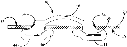
The side panel 20 has a handle 28 attached to it to allow the bag to be
carried in one
hand like a briefcase or suitcase. As shown in longitudinal section in FIG. 4
and in plan
view in FIG. 5, the handle 28 forms part of a handle strip 30 and lies
adjacent an outer face
32 of the side panel 20. The side panel 20 has a pair of circular holes 34
through which
project end regions of the handle strip 30 so that parts 36 of the end regions
contact parts of
an inner face 40 of the side panel bounding the holes 34. As shown in FIG. 5,
the handle
3
CA 02639540 2008-09-02
PPL001
strip 30 has locations 42 of reduced width where the end regions extend
through the holes
34, the width of the handle strip at the reduced width locations matching the
width of the
circular holes 34. The end regions have parts 44 which are folded over onto,
and sealed
against, respective parts 36 at the holes 34. In addition, marginal areas 46
of the folded over
parts 44 contact and are sealed against areas of the inner face 40 bounding
the holes 34. The
sealing zones in this and subsequent FIGs. are shown as cross-hatched areas.
The
arrangement is such that the folded parts 36, 44 at each hole provide locally
thicker and
stronger reinforcing strips where the handle strip joins the side panel 20.
The folded over
parts also act to seal the holes 34 against entry of contaminants from outside
the bag and
from escape of contents from within the bag, these being particularly
important if the bag is
to carry foodstuffs. Obviously, if sealing is not important, then the handle
can be attached
to the bag in a non-sealing arrangement provided that the strength of the
handle anchor
region is not compromised.
Referring to FIGs. 6 and 7, an alternative embodiment of the invention is
shown
using a pouch bag similar to that shown in FIGs. 1 to 3. As in the FIG. 4
embodiment,
handle 28 forms part of a handle strip 30 and lies adjacent an outer face 32
of the side panel
20. The side panel has a pair of circular holes 34 through which project end
regions 48 of
the handle strip 30 so that the end regions contact an inner face 40 of the
side panel. In
contrast with the embodiment of FIGs. 4 and 5, a reinforcing strip 50 is not
formed as
extensions of the handle strip, but is instead a completely separate element
located on the
inside of the side panel 20. Areas of the handle strip end regions and areas
of the reinforcing
strip 50 are sealed together through the holes 34. Reinforcing strip 50 is
wider than the
handle strip end regions and the sealing zone is made larger than the holes 34
so that
marginal areas of the handle strip end regions and of the reinforcing strip
are sealed to each
other and to areas of the inner face 40.
Referring to FIGs. 8 and 9, a further embodiment of the invention is shown
using a
pouch bag similar to that shown in FIGs. 1 to 3. In this embodiment, a handle
strip has a
handle part and end regions. The handle strip is located completely on one
side of a side
panel 20, adjacent its outer face 32. A reinforcing strip 51 is located on the
other side of the
side panel 20 adjacent its inner face. As in the FIG. 4, embodiment, the side
panel 20 has a
4
CA 02639540 2008-09-02
PPL001
pair of circular holes which are covered by areas of the handle strip 30 and
the reinforcing
strip 51 with the handle strip and the reinforcing strip being sealed together
through the
holes. The sealing zones are made larger than the holes so that areas of the
reinforcing strip
surrounding the holes are sealed to the inner face of the side panel 20.
In each of the embodiments of the invention described, the bag, the handle
strip and
the reinforcing strip are formed from heat-sealable thermoplastics film
materials and sealing
is effected by heat sealing. Such materials include, by way of example and not
limitation,
polyolefins such as polyethylene and polypropylene, polyesters, vinyl
polymers, and the like.
The materials may be low-, medium- or high-density polymers and may be single
or multi-
layer composite material. Composite laminated materials may include adhesive
layers.
Suitable materials for adhesive or tie layers are adhesive resins such as
Mitsui Petrochemical's
ADMER . Sealing resins such as ethylene vinyl acetate may be used to improve
sealing of
certain polymer layers and the use of such sealing resins may obviate the use
of adhesive tie
layers. The invention contemplates the use of thermoplastics films which are
made of, or
which include, a barrier sheet material such as, for example, EVOH which
provides a barrier
generally preventing the transmission of gases.
The thickness of the film material is selected mainly on the basis of the
intended
weight the bag must carry and generally ranges from about 2 to 20 mils.
While thermoplastics film is preferred as a construction material, the
invention is also
applicable to bags formed of other sheet materials such as stiff paper or card
and to other
sheet or foil materials. The type of thermoplastics or other sheet material
used will depend
on the purposes to which the bag is to be put, whether it is easy to handle in
manufacturing,
whether it can be readily printed upon, whether it is waterproof, whether it
is strong enough
to resist tearing or bulging, etc.
In one example, the film material of the handle strip and the reinforcing
strip are
formed from two layers of a composite sheet of coextruded, alternating layers
of
thermoplastics and adhesive in the following order: 1.75 - 1.9 mils
polyethylene, 0.35 - 0.5
mils adhesive polymer, 0.5 mils nylon, 0.35 - 0.5 mils adhesive polymer, 1.75 -
1.9 mils
CA 02639540 2008-09-02
PPL001
polyethylene. This composite sheet can be bought from a number of extrusion
companies,
including the Pliant Corporation. The handle can be made by laminating
together two layers
of the composite sheet described above using an adhesive that may be solvent
based or
solvent-less (i.e. 100% solids). The strips can be formed from other film
material depending
on the particular properties required of the handle and the reinforcement from
the viewpoint
of the bag function and its manufactuability. An alternative composite
structure
thermoplastics has a multi-ply layered material with outer layers of
polyethylene and a core
layer of nylon. The particular selection of ply materials and the number of
layers of each
material is chosen for the particular properties desired in the bag. Thus,
polyethylene has
good heat sealing properties and relatively high strength. A copolymer
polyethylene with
high elastomeric content can be used where a soft handle is required. The
material of both
the handle strip and the reinforcing strip is selected to achieve required
reinforcing action
where the handle strip is anchored to a bag panel. For example, thermoplastic
films can be
used which have been oriented during manufacture to impart particular
mechanical strength
along the line of the handle or at other critical stress sites. Such oriented
strength can be
imparted, as is known, by for example stretching at ambient temperatures, melt
orienting
during extrusion, etc.
Heat sealing and bonding of layers of sheet material is effected by the
application of
temperature and pressure for a predetermined time at locations where the
layers are to be
heat sealed. The particular temperature, pressure and time are selected based
on the
particular nature of the sheet materials being bonded together. Bonding is
typically effected
at multiple bonding stations, with the bonded material subsequently being
cooled. For
materials such as stiff paper or card which cannot be heat sealed, an adhesive
is used at the
contact zones between the handle strip and the reinforcing strip, with
adhesive being used
also where the reinforcing strip and the handle strip, other than the handle
part, contact the
surfaces of the panel within which the handle is anchored.
It will be appreciated that many variations are possible in the design of a
bag and
handle arrangement using the principles of the invention. For example, a
circular shape is
used for the holes 34 because this shape acts to distributes forces around the
edge of the
holes when the bag is lifted by the handle and so reduces the chance of the
bag or handle
6
CA 02639540 2008-09-02
PPL001
material tearing. However, other shapes can be utilized depending on the
properties
required at the joint between the handle strip 30 and the reinforcing strip
and the
relationship of that joint with the bag panel in which the joint is located.
Thus, the holes can
be of oval, slot, D or other suitable form.
In addition, although the preferred embodiments have two spaced holes, more
that
two holes can be used with the handle strip and the reinforcing strip sealed
together at some
or all of the holes. In a further alternative, a multiplicity of small
perforations is made in the
bag panel so that the handle strip and the reinforcing strip at each contact
site are sealed
together effectively through a grid or lattice portion of the bag panel.
A method of manufacturing a bag and handle arrangement according to one
embodiment of the invention will now be described, the manufacturing method
having
particular application to the embodiment of bag illustrated in FIGs. 4 and 5.
As shown in
FIG. 10, bag web 60 of thermoplastic film material is unrolled from a stock
roll and is driven
around rollers (not shown) through a plurality of stations in which any of a
number of
operations is performed. These can include any or all of (a) folding, (b)
cutting, (c)
punching, (d) forming or adding gusset pieces, (e) forming or adding
reinforcing areas, (f)
application of adhesive (g) heat sealing, (h) cooling, (i) fitting elements of
a press-to-dose or
other fastener, etc.
The bag web 60 shown is suitable for forming a pouch bag of the form shown in
FIGs. 1 to 3, and, as shown in broken line, has areas 66 which are to become
the bag front
and back panels, and areas 68 which are to become the opposed side panels of
the bag, the
side panels also to form gusset regions in the completed bag. Typically, for a
pouch bag of
the sort illustrated in FIG. 4, gusset areas are formed in the sides of the
pouch bag, one end
is either left open for later filling or is sealed shut, and the other end is
fitted with a closure
arrangement such as a push-to-close or a slider arrangement. Details of the
manufacturing
process to the extent they relate to such steps form no part of the invention
and will not be
described in detail. It will be understood that the pouch bag is just one form
of bag that can
be made by a manufacturing method according to the invention. Bags having
other shapes,
panels, closures, gussets, materials, etc., can be manufactured using the
method of the
7
CA 02639540 2008-09-02
PPL001
invention to be described presently with appropriate modifications depending
on the
particular form of bag being made.
In the preparation of a bag with handle arrangement according to one
embodiment
of the invention, and as illustrated in FIG. 10, the continuous bag web 60 is
driven through a
punching station where it is halted momentarily and pairs of holes 70 are
punched into it.
As shown, the holes are punched into a part of the bag which is intended to
function as a
side panel gusset. The holes are circular, although as previously indicated,
depending on the
properties required of the handle, such as its strength, resistance to
tearing, etc., the holes
can be made in different shapes.
Referring to FIGs. 11 and 12, a continuous web of handle strip material 62 is
also
unrolled from a stock roll. The web of handle strip material is used to form a
series of
handle strips as shown in outline (broken line) in FIG. 11 for side delivery
and FIG. 12 for
end delivery, as shown by arrow 64. The handle strip web is driven around
rollers (not
shown) to a punching station at which semicircular cut-outs are punched from
the web to
form regions 72 of reduced width. The width of each region 72 is made the same
as the
diameter of the holes 70 in the bag web to aid in subsequent threading and
autolocation
steps as will be described presently. The handle strips are formed with
rounded end
portions 74 although alternative end shapes are possible.
The bag web 60 and the handle strip web 62 are then fed to a threading station
where the webs are momentarily halted to allow a handle strip 30 to be
separated from the
handle strip web 62 and to be attached to a suspended part of the bag web 60.
In one
embodiment, a separated handle strip is delivered from the side as shown in
FIG. 11. As
shown in FIG. 13, the handle strip 62 is laid up in a bent configuration
against a transfer
head 76. The handle strip is held in position by a vacuum applied at the
transfer head 76,
the transfer head being shaped and dimensioned such that end regions 74 of the
handle strip
are curled and project freely beyond the transfer head. The transfer head is
moved towards
the suspended bag web 60 so that the handle strip end regions74 are inserted
through the
holes 70. Retractable gripping heads 82 open as the end portions 74 of the
handle pattern
piece are inserted through the holes 70. Prior to the vacuum being released,
each gripping
8
CA 02639540 2008-09-02
PPL001
head is closed over and grips a respective end region of the handle strip. The
gripping heads
are then retracted to pull the end portions 74 fully through the holes 70 and
to straighten the
handle pattern piece whereupon the gripping heads 82 are opened. As the handle
strip
straightens, it reaches a position where the reduced width regions 72
automatically locate at
the centre of the holes 70 whereupon the gripping heads 82 are opened.
In a variation of the transfer head, instead of, or in addition to, the
vacuum,
retractable contact claws are used at the transfer head to temporarily clamp
the handle strip
against finger-shaped parts of the transfer head prior to the transfer head
being brought
close to the bag web to thread the handle strip end regions into the holes.
The contact claws
are released after the threading action is completed. In an alternative
embodiment of the
threading station, the handle strip web is end-delivered as shown in FIG. 12.
A variation of
the transfer head is used which threads the free end of the handle strip web
into one of the
pair of holes in the bag web. The handle strip is then detached from the
handle strip web
and the transfer head bends the detached handle strip to enable threading of
the other end
of the handle strip into the other of the pair of holes. The linking of the
handle strip to the
bag web is effected using a vacuum and/or gripping head arrangement similar to
that
described with reference to FIG. 13.
The bag web with the handle strip in place is then fed to a first heat sealing
station.
At the first heat sealing station, the end regions 74 which project through
and lie adjacent the
lower surface of the bag web 60 are tack sealed to the bag web. The tack seal
serves to fix
the bag web and handle strip in a proper disposition for subsequent
processing. It also
initiates a folding action in each part of the handle strip projecting through
the spaced holes
70 to form folded portions. These folded portions are shown in finished form
as elements
36 and 44 in FIG. 4. At a subseqent heat sealing station, the folded over
portions are fully
folded by a retractable plate arrangement and heat sealed against the parts of
the handle strip
located in the holes 70, so as to seal and reinforce the holes. As indicated
with respect to
FIGs. 4 and 5, the folded over portions provide a two-part reinforcing strip
adjacent the
holes 70 with marginal parts of the strip also bonded to the bag web at what
will
subsequently become the inside surface of the bag. A two-part heat sealing
operation with
9
CA 02639540 2008-09-02
PPL001
ambient or accelerated cooling is used to create a strong bond and to limit
heat build-up
which might otherwise cause degradation of the thermoplastics material.
In the heat sealing operation, the heat sealing zone is made to extend over
the full
area of the folded material so that no part of the folded material is free.
Any free part of the
handle strip or reinforcing strip material is undesirable because it can be a
source of
weakness and a source of air and contaminant entry. It can also contribute to
an overly
bulky material which is undesirable especially if, at a later stage of bag
formation, the panel
containing the handle is to be folded to form a gusset area.
It is important in all bonding operations, whether by heat sealing or
adhesive, to
avoid channel leaks since these can be a source of entry of insects, air and
moisture which
can later attack and adulterate the contents of the bag if the contents are
edible materials
such as pet food. One source of channel leaks is wrinkling of the materials
being bonded.
In the case of thermoplastics, wrinkling and channel leaks are minimized by
ensuring that a
thermoplastics material is used which has good heat flow properties. For
example, high heat
flow can be obtained by increasing the elastomeric polythethylene content of a
polyethylene
layer, the regular polyethylene and elastomeric polyethylene forming a
tailored co-polymer.
However, the elastomeric content is not made so high as to adversely affect
the
machinability of the finish material or to render it unpleasantly tacky. A
suitable percentage
of elastomeric polyethylene is 23%.
The bag and handle embodiments of FIGs. 6 to 9 can be made using process steps
which are similar to the process steps described above, but tailored, as will
be understood by
those skilled in the art, to the particular design of bag and handle
arrangement.
The embodiments of the invention illustrated and described all relate to a bag
in
which the panel to which the handle is attached also functions as a gusset. It
will be
understood that the handle can be attached to any panel of the bag. The handle
can, for
example, be located in either side panel, either end panel or in a bottom
panel at end 12 of
the exemplary bag shown in FIGs. 1 to 3.
CA 02639540 2008-09-02
PPL001
There have been described herein various embodiments of a bag and handle
arrangement and manufacturing processes therefor, such arrangements and
processes having
features that distinguish the present invention from the prior art. It willbe
apparent to those
skilled in the art that the bag and manufacture of the disclosed invention may
be modified in
numerous ways and may assume many embodiments other than the preferred forms
specifically set out and described above. Accordingly, it is intended by the
appended claims
to cover all modifications of the invention which fall within the true spirit
and scope of the
invention.
11